
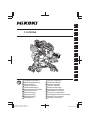
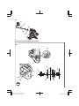
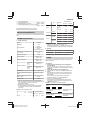
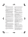
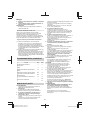
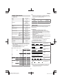
C 3612DRA
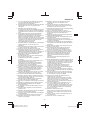
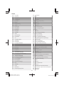
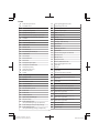
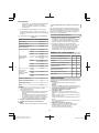
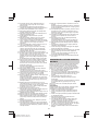
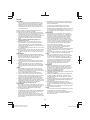
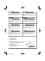
en Handling instructions
de Bedienungsanleitung
fr Mode d’emploi
it Istruzioni per l’uso
nl Gebruiksaanwijzing
es Instrucciones de manejo
pt Instruções de uso
sv Bruksanvisning
da Brugsanvisning
no Bruksanvisning
fi Käyttöohjeet
el Οδηγίες χειρισμού
pl Instrukcja obsługi
hu Kezelési utasítás
cs Návod k obsluze
tr Kullanım talimatları
ro Instrucţiuni de utilizare
sl Navodila za rokovanje
sk Pokyny na manipuláciu
bg Инструкция за експлоатация
sr Uputstvo za rukovanje
hr Upute za rukovanje
en
de
fr
it
nl
es
pt
sv
da
no
fi
el
pl
hu
cs
tr
ro
sl
sk
bg
sr
hr
2023/08/31 18:21:53Stylesheet: EU Version: 2023.8.18
C3612DRA_C99749371_309_EU

2
I
l
l
u
s
t
L
i
s
t
1
5
6
7
8
9
10
11
12
13
14
15
52
17
18
19
20
21
22
37 5
42
41
10
12
40
18
16
19
23
22
24
39
38
34
23
24
25
26
27
28
29
30
31
33
34 35
59
36
1
2
3
4
32
16
2023/08/31 18:21:53Stylesheet: EU Version: 2023.8.18
C3612DRA_C99749371_309_EU

3
2 3
5
43
1
2
4
1
2
5
44
5
4 – ø9 mm
327 mm 282 mm
255.5 mm
16 48
45 46
47
6
40
49
7
9
1
22
1
1
2023/08/31 18:21:53Stylesheet: EU Version: 2023.8.18
C3612DRA_C99749371_309_EU

4
8
7
51
50 2
9
110
111
52
109
107
108
16
10
12
a
53
b
54 12
13
55
11
11 56
2
12
57 32 32 28 28 32
57
28
a b c
57
2023/08/31 18:21:53Stylesheet: EU Version: 2023.8.18
C3612DRA_C99749371_309_EU

5
13
30
58
113
29
14
14
58
15
114
15
41
16
18 18
20 19
27
22
66
9
17
24
23
22
21
27
20
18
36
35
59
2023/08/31 18:21:53Stylesheet: EU Version: 2023.8.18
C3612DRA_C99749371_309_EU

6
19
61
60
61
60
20
3
37
21
62
68
6766
65
64
63
22
ⓐ ⓑ ⓐ ⓑ
ⓐⓑ
32
6969
2023/08/31 18:21:53Stylesheet: EU Version: 2023.8.18
C3612DRA_C99749371_309_EU

7
23
10
41
70
11
11
2
2
3
3
24
73
72
71
66
25
11
74
2
67
2–3 mm
26
1
67
11
33
2
2
27
21
76
75
2023/08/31 18:21:53Stylesheet: EU Version: 2023.8.18
C3612DRA_C99749371_309_EU

8
28
25
19
20
22
24
76
29
77
78
79
80
81
82
30
67
84
83
78
81
80
31
86
85
58 87
88
58
86
32
64
85
89 87, 88
62
14, 30
33
74
11
90
ⓑ
25
2023/08/31 18:21:53Stylesheet: EU Version: 2023.8.18
C3612DRA_C99749371_309_EU

9
34
91
92
95
94
93
96
97
35
39
32
8
98
8
99
112
98 100
7575
17 mm
30 mm
76
2023/08/31 18:21:53Stylesheet: EU Version: 2023.8.18
C3612DRA_C99749371_309_EU

10
36
102 101
103
37
5
a b
38
11
22
11
22
39
11
41
a b
10
105
104
105 17
22
1
42
41
2023/08/31 18:21:53Stylesheet: EU Version: 2023.8.18
C3612DRA_C99749371_309_EU

11
40
31
41
51
31
106
2023/08/31 18:21:53Stylesheet: EU Version: 2023.8.18
C3612DRA_C99749371_309_EU

English (Original instructions)
12
GENERAL POWER TOOL SAFETY
WARNINGS
WARNING
Read all safety warnings, instructions, illustrations
and specifications provided with this power tool.
Failure to follow all instructions listed below may result in
electric shock, fire and/or serious injury.
Save all warnings and instructions for future
reference.
The term “power tool” in the warnings refers to your mains-
operated (corded) power tool or battery-operated
(cordless) power tool.
1) Work area safety
a) Keep work area clean and well lit.
Cluttered or dark areas invite accidents.
b) Do not operate power tools in explosive
atmospheres, such as in the presence of
flammable liquids, gases or dust.
Power tools create sparks which may ignite the dust
or fumes.
c) Keep children and bystanders away while
operating a power tool.
Distractions can cause you to lose control.
2) Electrical safety
a) Power tool plugs must match the outlet. Never
modify the plug in any way. Do not use any
adapter plugs with earthed (grounded) power
tools.
Unmodified plugs and matching outlets will reduce
risk of electric shock.
b) Avoid body contact with earthed or grounded
surfaces, such as pipes, radiators, ranges and
refrigerators.
There is an increased risk of electric shock if your
body is earthed or grounded.
c) Do not expose power tools to rain or wet
conditions.
Water entering a power tool will increase the risk of
electric shock.
d) Do not abuse the cord. Never use the cord for
carrying, pulling or unplugging the power tool.
Keep cord away from heat, oil, sharp edges or
moving parts.
Damaged or entangled cords increase the risk of
electric shock.
e) When operating a power tool outdoors, use an
extension cord suitable for outdoor use.
Use of a cord suitable for outdoor use reduces the
risk of electric shock.
f) If operating a power tool in a damp location is
unavoidable, use a residual current device
(RCD) protected supply.
Use of an RCD reduces the risk of electric shock.
3) Personal safety
a) Stay alert, watch what you are doing and use
common sense when operating a power tool.
Do not use a power tool while you are tired or
under the influence of drugs, alcohol or
medication.
A moment of inattention while operating power tools
may result in serious personal injury.
b) Use personal protective equipment. Always
wear eye protection.
Protective equipment such as a dust mask, non-skid
safety shoes, hard hat or hearing protection used for
appropriate conditions will reduce personal injuries.
c) Prevent unintentional starting. Ensure the
switch is in the off-position before connecting
to power source and/or battery pack, picking
up or carrying the tool.
Carrying power tools with your finger on the switch
or energising power tools that have the switch on
invites accidents.
d) Remove any adjusting key or wrench before
turning the power tool on.
A wrench or a key left attached to a rotating part of
the power tool may result in personal injury.
e) Do not overreach. Keep proper footing and
balance at all times.
This enables better control of the power tool in
unexpected situations.
f) Dress properly. Do not wear loose clothing or
jewellery. Keep your hair and clothing away
from moving parts.
Loose clothes, jewellery or long hair can be caught
in moving parts.
g) If devices are provided for the connection of
dust extraction and collection facilities, ensure
these are connected and properly used.
Use of dust collection can reduce dust-related
hazards.
h) Do not let familiarity gained from frequent use
of tools allow you to become complacent and
ignore tool safety principles.
A careless action can cause severe injury within a
fraction of a second.
4) Power tool use and care
a) Do not force the power tool. Use the correct
power tool for your application.
The correct power tool will do the job better and
safer at the rate for which it was designed.
b) Do not use the power tool if the switch does not
turn it on and off.
Any power tool that cannot be controlled with the
switch is dangerous and must be repaired.
c) Disconnect the plug from the power source
and/ or remove the battery pack, if detachable,
from the power tool before making any
adjustments, changing accessories, or storing
power tools.
Such preventive safety measures reduce the risk of
starting the power tool accidentally.
d) Store idle power tools out of the reach of
children and do not allow persons unfamiliar
with the power tool or these instructions to
operate the power tool.
Power tools are dangerous in the hands of untrained
users.
e) Maintain power tools and accessories. Check
for misalignment or binding of moving parts,
breakage of parts and any other condition that
may affect the power toolʼs operation. If
damaged, have the power tool repaired before
use.
Many accidents are caused by poorly maintained
power tools.
f) Keep cutting tools sharp and clean.
Properly maintained cutting tools with sharp cutting
edges are less likely to bind and are easier to
control.
g) Use the power tool, accessories and tool bits
etc. in accordance with these instructions,
taking into account the working conditions and
the work to be performed.
Use of the power tool for operations different from
those intended could result in a hazardous situation.
h) Keep handles and grasping surfaces dry, clean
and free from oil and grease.
2023/08/31 18:21:53Stylesheet: EU Version: 2023.8.18
C3612DRA_C99749371_309_EU

English
13
Slippery handles and grasping surfaces do not allow
for safe handling and control of the tool in
unexpected situations.
5) Battery tool use and care
a) Recharge only with the charger specified by the
manufacturer.
A charger that is suitable for one type of battery
pack may create a risk of fire when used with
another battery pack.
b) Use power tools only with specifically
designated battery packs.
Use of any other battery packs may create a risk of
injury and fire.
c) When battery pack is not in use, keep it away
from other metal objects, like paper clips,
coins, keys, nails, screws or other small metal
objects, that can make a connection from one
terminal to another.
Shorting the battery terminals together may cause
burns or a fire.
d) Under abusive conditions, liquid may be
ejected from the battery; avoid contact. If
contact accidentally occurs, flush with water. If
liquid contacts eyes, additionally seek medical
help.
Liquid ejected from the battery may cause irritation
or burns.
e) Do not use a battery pack or tool that is
damaged or modified.
Damaged or modified batteries may exhibit
unpredictable behaviour resulting in fire, explosion
or risk of injury.
f) Do not expose a battery pack or tool to fire or
excessive temperature.
Exposure to fire or temperature above 130°C may
cause explosion.
g) Follow all charging instructions and do not
charge the battery pack or tool outside the
temperature range specified in the instructions.
Charging improperly or at temperatures outside the
specified range may damage the battery and
increase the risk of fire.
6) Service
a) Have your power tool serviced by a qualified
repair person using only identical replacement
parts.
This will ensure that the safety of the power tool is
maintained.
b) Never service damaged battery packs.
Service of battery packs should only be performed
by the manufacturer or authorized service providers.
PRECAUTION
Keep children and infirm persons away.
When not in use, tools should be stored out of reach
of children and infirm persons.
SAFETY INSTRUCTIONS FOR MITER
SAW
1. Miter saws are intended to cut wood or wood-like
products, they cannot be used with abrasive cut-
off wheels for cutting ferrous material such as
bars, rods, studs, etc.
Abrasive dust causes moving parts such as the lower
guard to jam. Sparks from abrasive cutting will burn the
lower guard, the kerf insert and other plastic parts.
2. Use clamps to support the workpiece whenever
possible. If supporting the workpiece by hand, you
must always keep your hand at least 100mm from
either side of the saw blade. Do not use this saw to
cut pieces that are too small to be securely
clamped or held by hand.
If your hand is placed too close to the saw blade, there
is an increased risk of injury from blade contact.
3. The workpiece must be stationary and clamped or
held against both the fence and the table. Do not
feed the workpiece into the blade or cut "freehand"
in any way.
Unrestrained or moving workpieces could be thrown at
high speeds, causing injury.
4. Push the saw through the workpiece. Do not pull
the saw through the workpiece. To make a cut,
raise the saw head and pull it out over the
workpiece without cutting, start the motor, press
the saw head down and push the saw through the
workpiece.
Cutting on the pull stroke is likely to cause the saw
blade to climb on top of the workpiece and violently
throw the blade assembly towards the operator.
5. Never cross your hand over the intended line of
cutting either in front or behind the saw blade.
Supporting the workpiece “cross handed” i.e. holding
the workpiece to the right of the saw blade with your left
hand or vice versa is very dangerous.
6. Do not reach behind the fence with either hand
closer than 100mm from either side of the saw
blade, to remove wood scraps, or for any other
reason while the blade is spinning.
The proximity of the spinning saw blade to your hand
may not be obvious and you may be seriously injured.
7. Inspect your workpiece before cutting. If the
workpiece is bowed or warped, clamp it with the
outside bowed face toward the fence. Always
make certain that there is no gap between the
workpiece, fence and table along the line of the
cut.
Bent or warped workpieces can twist or shift and may
cause binding on tile spinning saw blade while cutting.
There should be no nails or foreign objects in the
workpiece.
8. Do not use the saw until the table is clear of all
tools, wood scraps, etc., except for the workpiece.
Small debris or loose pieces of wood or other objects
that contact the revolving blade can be thrown with high
speed.
9. Cut only one workpiece at a time.
Stacked multiple workpieces cannot be adequately
clamped or braced and may bind on the blade or shift
during cutting.
10. Ensure the miter saw is mounted or placed on a
level, firm work surface before use.
A level and firm work surface reduces the risk of the
miter saw becoming unstable.
11. Plan your work. Every time you change the bevel
or miter angle setting, make sure the adjustable
fence is set correctly to support the workpiece and
will not interfere with the blade or the guarding
system.
Without turning the tool “ON” and with no workpiece on
the table, move the saw blade through a complete
simulated cut to assure there will be no interference or
danger of cutting the fence.
12. Provide adequate support such as table
extensions, saw horses, etc. for a workpiece that is
wider or longer than the table top.
Workpieces longer or wider than the miter saw table
can tip if not securely supported. If the cut-off piece or
workpiece tips, it can lift the lower guard or be thrown
by the spinning blade.
13. Do not use another person as a substitute for a
table extension or as additional support.
2023/08/31 18:21:53Stylesheet: EU Version: 2023.8.18
C3612DRA_C99749371_309_EU

English
14
Unstable support for the workpiece can cause the blade
to bind or the workpiece to shift during the cutting
operation pulling you and the helper into the spinning
blade.
14. The cut-off piece must not be jammed or pressed
by any means against the spinning saw blade.
If confined, i.e. using length stops, the cut-off piece
could get wedged against the blade and thrown
violently.
15. Always use a clamp or a fixture designed to
properly support round material such as rods or
tubing.
Rods have a tendency to roll while being cut, causing
the blade to "bite" and pull the work with your hand into
the blade.
16. Let the blade reach full speed before contacting
the workpiece.
This will reduce the risk of the workpiece being thrown.
17. If the workpiece or blade becomes jammed, turn
the miter saw off. Wait for all moving parts to stop
and disconnect the plug from the power source
and/or remove the battery pack. Then work to free
the jammed material.
Continued sawing with a jammed workpiece could
cause lass of control or damage to the miter saw.
18. After finishing the cut, release the switch, hold the
saw head down and wait for the blade to stop
before removing the cut-off piece.
Reaching with your hand near the coasting blade is
dangerous.
19. Hold the handle firmly when making an incomplete
cut or when releasing the switch before the saw
head is completely in the down position.
The braking action of the saw may cause the saw head
to be suddenly pulled downward, causing a risk of
injury.
PRECAUTIONS ON USING SLIDE
COMPOUND MITER SAW
1. Keep the floor area around the machine level. Well
maintained and free of loose materials e.g. chips and
cut-offs.
2. Provide adequate general or localized lighting.
3. Do not use power tools for applications other than those
specified in the handling instructions.
4. Repairing must be done only by authorized service
facility. Manufacturer is not responsible for any
damages and injuries due to the repair by the
unauthorized persons as well as the mishandling of the
tool.
5. To ensure the designed operational integrity of power
tools, do not remove installed covers or screws.
6. Do not touch movable parts or accessories unless the
power source has been disconnected.
7. Use your tool at lower input than specified on the
nameplate; otherwise, the finish may be spoiled and
working efficiency reduced due to motor overload.
8. Do not wipe plastic parts with solvent. Solvents such as
gasoline, thinner, benzine, carbon tetrachloride,
alcohol, may damage and crack plastic parts. Do not
wipe them with such solvent. Clean plastic parts with a
soft cloth lightly dampened with soapy water.
9. Use only original HiKOKI replacement parts.
10. This tool should only be disassembled for replacement
of carbon brushes.
11. Never cut ferrous metals or masonry.
12. Adequate general or localized lighting is provided.
Stock and finished workpieces are located close to the
operators normal working position.
13. Wear suitable personal protective equipment when
necessary, this could include:
Hearing protection to reduce the risk of induced hearing
loss.
Eye protection to reduce the risk of injuring an eye.
Respiratory protection to reduce the risk of inhalation of
harmful dust.
Gloves for handling saw blades (saw blades shall be
carried in a holder wherever practicable) and rough
material.
14. The operator is adequately trained in the use,
adjustment and operation of the machine.
15. Refrain from removing any cut-offs or other parts of the
workpiece from the cutting area whilst the machine is
running and the saw head is not in the rest position.
16. Never use the slide compound miter saw with its lower
guard locked in the open position.
17. Ensure that the lower guard moves smoothly.
18. Do not use the saw without guards in position, in good
working order and properly maintained.
19. Use correctly sharpened saw blades. Observe the
maximum speed marked on the saw blade.
20. Do not use saw blades which are damaged or
deformed.
21. Do not use saw blades manufactured from high speed
steel.
22. Use only saw blades recommended by HiKOKI.
23. The saw blades should be 305mm external diameter.
24. Select the correct saw blade for the material to be cut.
25. Never operate the slide compound miter saw with the
saw blade turned upward or to the side.
26. Ensure that the workpiece is free of foreign matter such
as nails.
27. Replace the table insert when worn.
28. Do not use the saw to cut other than aluminium, wood
or similar materials.
29. Do not use the saw to cut other materials than those
recommended by the manufacturer.
30. Blade replacement procedure, including the method for
repositioning and a warning that this must be carried out
correctly.
31. Connect the slide compound miter saw to a dust
collecting device when sawing wood.
32. Take care when slotting.
33. When transporting or carrying the tool, do not grasp the
holder. Grasp the handle instead of the holder.
34. Start cutting only after motor revolution reaches
maximum speed.
35. Promptly cut OFF the switch when abnormality
observed.
36. Shut off power and wait for saw blade to stop before
servicing or adjusting tool.
37. During a miter or bevel cut the blade should not be lifted
until it has stopped rotation completely.
38. During slide cutting operation, the saw must be pushed
and slided away from the operator.
39. Take all the possibility of residual risks in cutting
operation into your consideration, such as the
inadvertent access to moving parts on slide mechanical
parts on machine and so on.
40. Ensure before each cut that the machine is stable.
41. Do not stand in a line with the saw blade In front of the
machine. Always stand aside of the saw blade. This
protects your body against possible kickback. Keep
hands, fingers and arms away from the rotating saw
blade.
Do not cross your arms when operating the tool arm.
42. If the saw blade should become jammed, switch the
machine off and hold the workpiece until the saw blade
comes to a complete stop. To prevent kickback, the
workpiece may not be moved until after the machine
2023/08/31 18:21:53Stylesheet: EU Version: 2023.8.18
C3612DRA_C99749371_309_EU

English
15
has come to a complete stop.
Correct the cause for the jamming of the saw blade
before restarting the machine.
43. When the saw head is in the down position, never
release the hand that is gripping the handle.
Doing so could snap the saw head up, forcing the tool
to fall and possibly cause injury.
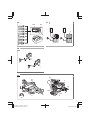
44. Make sure to securely hold the tool during operation.
Failure to do so can result in accidents or injuries.
(Fig.2)
45. Do not look directly into the light. Such actions could
result in eye injury.
Wipe off any dirt or grime attached to the lens of the
LED light with a soft cloth, being careful not to scratch
the lens.
Scratches on the lens of the LED light can result in
decreased brightness.
46. Always charge the battery at a temperature of 0°C–
40°C. A temperature of less than 0°C will result in over
charging which is dangerous. The battery cannot be
charged at a temperature higher than 40°C. The most
suitable temperature for charging is that of 20°C–25°C.
47. Do not use the charger continuously.
When one charging is completed, leave the charger for
about 15minutes before the next charging of battery.
48. Do not allow foreign matter to enter the hole for
connecting the rechargeable battery.
49. Never disassemble the rechargeable battery and
charger.
50. Never short-circuit the rechargeable battery. Short-
circuiting the battery will cause a great electric current
and overheat. It results in burn or damage to the
battery.
51. Do not dispose of the battery in fire. If the battery is
burnt, it may explode.
52. Bring the battery to the shop from which it was
purchased as soon as the post-charging battery life
becomes too short for practical use. Do not dispose of
the exhausted battery.
53. Do not insert objects into the air ventilation slots of the
charger.
Inserting metal objects or inflammables into the charger
air ventilation slots will result in electrical shock hazard
or a damaged charger.
54. When using this unit continuously, the unit may
overheat, leading to damage in the motor and switch.
Therefore, whenever the housing becomes hot, give the
tool a break for a while.
55. Make sure that the battery is installed firmly. If it is at all
loose it could come off and cause an accident.
56. Do not use the product if the tool or the battery
terminals (battery mount) are deformed.
Installing the battery could cause a short circuit that
could result in smoke emission or ignition.
57. Keep the tool’s terminals (battery mount) free of swarf
and dust.
○ Prior to use, make sure that swarf and dust have not
collected in the area of the terminals.
○ During use, try to avoid swarf or dust on the tool from
falling on the battery.
○ When suspending operation or after use, do not leave
the tool in an area where it may be exposed to falling
swarf or dust.
Doing so could cause a short circuit that could result in
smoke emission or ignition.
58. Always use the tool and battery at temperatures
between -5°C and 40°C.
CAUTION ON LITHIUM-ION BATTERY
To extend the lifetime, the lithium-ion battery equips with
the protection function to stop the output.
In the cases of 1 to 3 described below, when using this
product, even if you are pulling the switch, the motor may
stop. This is not the trouble but the result of protection
function.
1. When the battery power remaining runs out, the motor
stops.
In such a case, charge it up immediately.
2. If the tool is overloaded, the motor may stop. In this
case, release the switch of tool and eliminate causes of
overloading. After that, you can use it again.
3. If the battery is overheated under overload work, the
battery power may stop.
In this case, stop using the battery and let the battery
cool. After that, you can use it again.
Furthermore, please heed the following warning and
caution.
WARNING
In order to prevent any battery leakage, heat generation,
smoke emission, explosion and ignition beforehand, please
be sure to heed the following precautions.
1. Make sure that swarf and dust do not collect on the
battery.
○ During work make sure that swarf and dust do not fall
on the battery.
○ Make sure that any swarf and dust falling on the power
tool during work do not collect on the battery.
○ Do not store an unused battery in a location exposed to
swarf and dust.
○ Before storing a battery, remove any swarf and dust
that may adhere to it and do not store it together with
metal parts (screws, nails, etc.).
2. Do not pierce battery with a sharp object such as a nail,
strike with a hammer, step on, throw or subject the
battery to severe physical shock.
3. Do not use an apparently damaged or deformed
battery.
4. Do not use the battery for a purpose other than those
specified.
5. If the battery charging fails to complete even when a
specified recharging time has elapsed, immediately
stop further recharging.
6. Do not put or subject the battery to high temperatures or
high pressure such as into a microwave oven, dryer, or
high pressure container.
7. Keep away from fire immediately when leakage or foul
odor are detected.
8. Do not use in a location where strong static electricity
generates.
9. If there is battery leakage, foul odor, heat generated,
discolored or deformed, or in any way appears
abnormal during use, recharging or storage,
immediately remove it from the equipment or battery
charger, and stop use.
10. Do not immerse the battery or allow any fluids to flow
inside. Conductive liquid ingress, such as water, can
cause damage resulting in fire or explosion. Store your
battery in a cool, dry place, away from combustible and
flammable items. Corrosive gas atmospheres must be
avoided.
11. Do not give a strong shock to the switch panel or break
it. It may lead to a trouble.
CAUTION
1. If liquid leaking from the battery gets into your eyes, do
not rub your eyes and wash them well with fresh clean
water such as tap water and contact a doctor
immediately.
If left untreated, the liquid may cause eye-problems.
2. If liquid leaks onto your skin or clothes, wash well with
clean water such as tap water immediately.
There is a possibility that this can cause skin irritation.
2023/08/31 18:21:53Stylesheet: EU Version: 2023.8.18
C3612DRA_C99749371_309_EU

English
16
3. If you find rust, foul odor, overheating, discolor,
deformation, and/or other irregularities when using the
battery for the first time, do not use and return it to your
supplier or vendor.
WARNING
If a conductive foreign matter enters in the terminal of
lithium ion battery, the battery may be shorted, causing fire.
When storing the lithium ion battery, obey surely the rules
of following contents.
○ Do not place conductive debris, nail and wires such as
iron wire and copper wire in the storage case.
○ To prevent shorting from occurring, load the battery in
the tool or insert securely the battery cover for storing
until the ventilator is not seen.
REGARDING LITHIUM-ION BATTERY
TRANSPORTATION
When transporting a lithium-ion battery, please observe the
following precautions.
WARNING
Notify the transporting company that a package contains a
lithium-ion battery, inform the company of its power output
and follow the instructions of the transportation company
when arranging transport.
○ Lithium-ion batteries that exceed a power output of
100Wh are considered to be in the freight classification
of Dangerous Goods and will require special application
procedures.
○ For transportation abroad, you must comply with
international law and the rules and regulations of the
destination country.
○ If the BSL36B18X is installed in the power tool, the
power output will exceed 100Wh and the unit will be
classified as Dangerous Goods for freight classification.
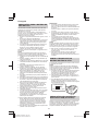
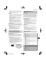
Wh
Power Output
2 to 3 digit number
USB DEVICE CONNECTION
PRECAUTIONS (UC18YSL3)
When an unexpected problem occurs, the data in a USB
device connected to this product may be corrupted or lost.
Always make sure to back up any data contained in the
USB device prior to use with this product.
Please be aware that our company accepts absolutely no
responsibility for any data stored in a USB device that is
corrupted or lost, nor for any damage that may occur to a
connected device.
WARNING
○ Prior to use, check the connecting USB cable for any
defect or damage.
Using a defective or damaged USB cable can cause
smoke emission or ignition.
○ When the product is not being used, cover the USB port
with the rubber cover.
Buildup of dust etc. in the USB port can cause smoke
emission or ignition.
NOTE
○ There may be an occasional pause during USB
recharging.
○ When a USB device is not being charged, remove the
USB device from the charger.
Failure to do so may not only reduce the battery life of a
USB device, but may also result in unexpected
accidents.
○ It may not be possible to charge some USB devices,
depending on the type of device.
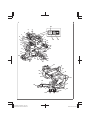
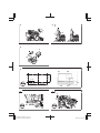
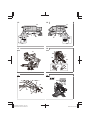
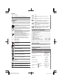
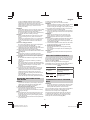
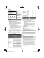
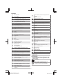
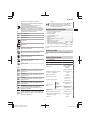
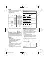
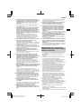
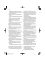
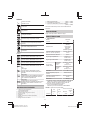
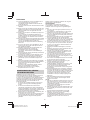
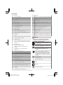
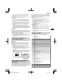
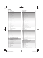
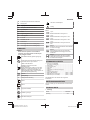
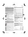
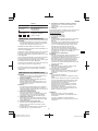
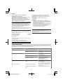
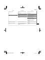
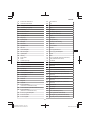
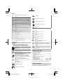
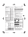
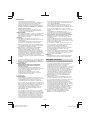
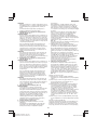
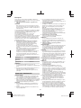
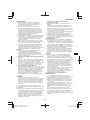
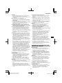
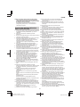
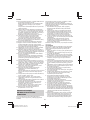
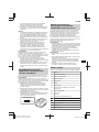
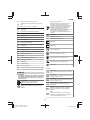
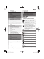
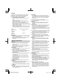
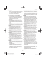
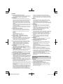
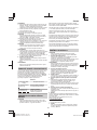
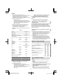
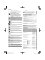
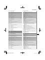
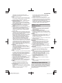
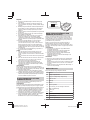
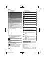
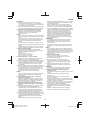
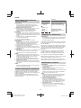
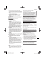
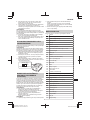
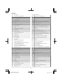
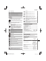
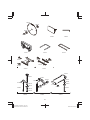
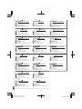
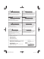
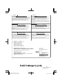
NAMES OF PARTS
The numbers in the list below correspond to Fig.1–Fig.41.
1Handle
2Gear case
3Lock-off button
4Motor head
5Battery
6Motor
7Dust bag
8Left hex. 10mm socket bolt
9Locking pin
10 Holder (A)
11 Hinge
12 Indicator (For bevel scale)
13 Set pin (A)
14 Sub fence (B)
15 Fence (B)
16 Base
17 Vise assembly
18 6mm machine screw
19 Miter scale
20 Indicator (For miter scale)
21 Bevel lock handle
22 Miter lock handle
23 Detent lever
24 Positive stop lever
25 Turntable
26 5mm machine screw
27 4mm screw
28 Table insert
29 Fence (A)
30 Sub fence (A)
31 Lower guard
32 Saw blade
33 Rotation direction
34 LED light
2023/08/31 18:21:53Stylesheet: EU Version: 2023.8.18
C3612DRA_C99749371_309_EU

English
17
35 Mode selector switch
36 LED light switch
37 Trigger switch
38 Name plate
39 Spindle lock
40 Holder
41 Slide securing knob
42 Carriage handle
43 Latch
44 Charge indicator lamp
45 Work bench
46 8mm nut
47 25mm thick work bench
48 8mm bolt
49 6mm bolt
50 Support bar
51 Dust port
52 Sub table
53 8mm set screw
(For left 45° bevel angle)
54 8mm set screw (For right angle)
55 8mm set screw
(For right 45° bevel angle)
56 8mm depth adjustment bolt
57 5mm machine screw
58 6mm wing bolt
59 Mode selector lamp
60 Line
61 Warning sign
62 Knob
63 Screw holder
64 Hex. socket set screw
65 Vise shaft
66 Fence
67 Workpiece
68 Vise plate
69 Marking (pre-marked)
70 Press down
71 6mm nut
72 Auxiliary board
73 6mm flat hd. screw
74 6mm depth adjustment bolt
75 Loosen
76 Tighten
77 6mm knob bolt (Optional accessory)
78 Holder (Optional accessory)
79 Steel square
80 6mm wing nut (Optional accessory)
81 Height adjustment bolt 6mm (Optional
accessory)
82 Base surface
83 Stopper (Optional accessory)
84 6mm wing bolt (Optional accessory)
85 Crown molding vise ass’y (Optional accessory)
86 6mm knob bolt
87 Crown molding stopper (L) (Optional accessory)
88 Crown molding stopper (R) (Optional accessory)
89 Crown molding
90 Bottom line of the groove
91 Dust extractor
92 Hose (id 38mm)
93 Adapter (Dust extractor's standard accessory)
94 Joint (C) (Optional accessory)
95 Dust collection adapter (Optional accessory)
96 Hose band (Optional accessory)
97 Duct
98 Washer (B)
99 8 mm hex. bar wrench
100 Washer (A)
101 Remaining battery indicator switch
102 Remaining battery indicator lamp
103 Display panel
104 Base grip
105 Piece of wood to secure the vise
106 Air gun
107 Holder
108 Height adjustment bolt 8mm
109 6mm wing bolt
110 6mm bolt
111 Steel square
2023/08/31 18:21:53Stylesheet: EU Version: 2023.8.18
C3612DRA_C99749371_309_EU

English
18
112 Dust guide
113 Mounting position of the sub fence (A)
114 Mounting position of the sub fence (B)
SYMBOLS
WARNING
The following show symbols used for the machine.
Be sure that you understand their meaning before
use.
C3612DRA:
Cordless Slide Compound Miter Saw
To reduce the risk of injury, user must read
instruction manual.
Only for EU countries
Do not dispose of electric tools together with
household waste material!
In observance of European Directive
2012/19/EU on waste electrical and electronic
equipment and its implementation in
accordance with national law, electric tools that
have reached the end of their life must be
collected separately and returned to an
environmentally compatible recycling facility.
Direct current
V
Rated voltage
n0
No-load speed
Switching ON
0
Switching OFF
Disconnect the battery
Always wear eye protection.
Always wear hearing protection.
Do not stare at operating lamp.
Warning
Battery
Lights ;
The battery remaining power is over 75%.
Lights ;
The battery remaining power is 50%–75%.
Lights ;
The battery remaining power is 25%–50%.
Lights ;
The battery remaining power is less than 25%.
Blinks ;
The battery remaining power is nearly empty.
Recharge the battery soonest possible.
Blinks ;
Output suspended due to high temperature.
Remove the battery from the tool and allow it to
fully cool down.
Blinks ;
Output suspended due to failure or malfunction.
The problem may be the battery so please
contact your dealer.
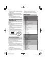
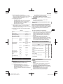
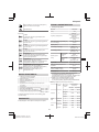
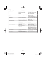
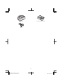
STANDARD ACCESSORIES
○ 305mm TCT Saw blade
(mounted on tool)......................................................... 1
○ Dust bag....................................................................... 1
○ 8 mm hex. bar wrench.................................................. 1
○ Vise Assembly ............................................................. 1
○ Holder .......................................................................... 1
○ Sub Fence (mounted on tool)....................................... 1
○ Holders ........................................................................ 2
○ Sub table assembly...................................................... 2
○ Battery (BSL36B18X) .......................... (WCZ):1, (NN):0
○ Battery Charger (UC18YSL3) .............. (WCZ):1, (NN):0
○ Battery cover (Code No. 329897) ........ (WCZ):1, (NN):0
Standard accessories are subject to change without notice.
APPLICATIONS
Cutting various types of aluminium sash and wood.
SPECIFICATIONS
1. Power tool
Model C3612DRA
Voltage 36 V
No-load speed
4000min-1
(Auto Switch mode) /
3200min-1
(High Torque mode)
Saw Blade Dimensions (oD × iD ×
Thickness) 305mm × 30mm ×
2.1mm
Maximum kerf 2.8mm
Miter Cutting Angle Right 0°–57°,
Left 0° – 45°
Bevel Cutting Angle Right 0°–45°,
Left 0°–45°
Compound Cutting
Angle
Bevel (Left)
0°–45° Miter (Left) 0°–45°,
(Right) 0°–45°
Bevel (Right)
0°–45° Miter (Right) 0°–45°,
(Left) 0°–45°
LED light Yes
2023/08/31 18:21:53Stylesheet: EU Version: 2023.8.18
C3612DRA_C99749371_309_EU

English
19
Battery available for this tool*1Multi volt battery
Machine Dimensions (Width ×
Depth × Height) 655mm × 873mm ×
724mm
Net weight*226.2kg
*1 Existing batteries (BSL3660/3620/3626, BSL18 and
BSL14 series) cannot be used with this tool. Use a multi
volt type battery.
*2 According to EPTA-Procedure 01/2014
Depending on attached battery.
The heaviest weight is measured with BSL36B18X.
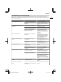
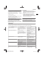
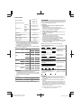
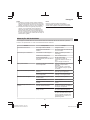
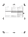
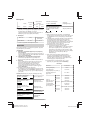
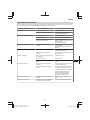
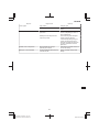
Table 1: Max. sawing dimension
Head Turntable Max. sawing dimension
Max. height Max. width
Miter 0
0 105 mm 312 mm
Left 45°
or
Right 45° 105 mm 220 mm
Right 57° 105 mm 170 mm
Bevel Left 45° 0 68 mm 312 mm
Right 45° 0 43 mm 312 mm
Compound
Left 45° Left 45° 68 mm 220 mm
Right 45° 68 mm 220 mm
Right 45° Left 45° 43 mm 220 mm
Right 45° 43 mm 220 mm
NOTE
Due to HiKOKI’s continuing program of research and
development, the specifications herein are subject to
change without prior notice.
2. Battery
Model Voltage Battery capacity
BSL36B18X 36 / 18 V *14.0 / 8.0 Ah *1
*1 The tool itself will automatically switch over.
CHARGING
Before using the power tool, charge the battery as follows.
<UC18YSL3>
1. Connect the charger’s power cord to the
receptacle.
When connecting the plug of the charger to a
receptacle, the charge indicator lamp will blink in red.
(See Table2)
2. Insert the battery into the charger.
Firmly insert the battery into the charger as shown in
Fig.4 (on page 3).
3. Charging
When inserting a battery in the charger, charging will
commence and the charge indicator lamp will blink in
blue.
When the battery becomes fully recharged, the charge
indicator lamp will light up in green. (See Table2)
(1) Charge indicator lamp indication
The indications of the charge indicator lamp will be as
shown in Table2, according to the condition of the
charger or the rechargeable battery.
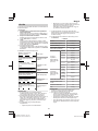
Table 2: Indications of the charge indicator lamp
ON/OFF at 0.5sec. intervals
(RED) Before charging *1
Lights for 0.5sec. at intervals of
1sec. (BLUE) Charged at less than
50%
Lights for 1sec. at intervals of
0.5sec. (BLUE) Charged at less than
80%
Lights continuously (BLUE) Charged at more
than 80%
Lights continuously (Continuous
buzzer sound: about 6sec.)
(GREEN) Charging complete
ON/OFF at 0.3sec. intervals
(RED) Overheat standby *2
ON/OFF at 0.1sec. intervals
(Intermittent buzzer sound:
about 2sec.) (PURPLE) Charging impossible
*3
NOTE
*1 If the red lamp continues to blink even after the charger
has been attached, check to confirm that the battery
has been fully inserted.
*2 Battery overheated. Unable to charge.
Although charging will start once the battery has cooled
down even when left in situ, the best practice is to
remove the battery and allow it to cool down in a
shaded, well-ventilated location before charging.
*3 Malfunction in the battery or the charger
– Fully insert the battery.
– Check to confirm that no foreign matter is stuck to
the battery mount or terminals. If there are no
foreign objects, it is probable that the battery or
charger is malfunctioning. Take it to your authorized
Service Center.
○ When the battery charger has been continuously used,
the battery charger will be heated, thus constituting the
cause of the failures. Once the charging has been
completed, give 5minutes rest until the next charging.
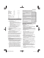
(2) Regarding the temperatures and charging time of the
battery (See Table3)
Table 3
Model UC18YSL3
Type of battery Li-ion
Charging voltage 14.4–18 V
Temperatures at which the
battery can be recharged 0°C–50°C
2023/08/31 18:21:53Stylesheet: EU Version: 2023.8.18
C3612DRA_C99749371_309_EU

English
20
Charging time for
battery capacity,
approx. (At 20°C)
1.5Ah 15min
2.0Ah 20min
2.5Ah 25min
3.0Ah 20min
(BSL1430C,BSL1830C:
30min)
4.0Ah 26 min
(BSL1840M: 40min)
5.0Ah 32min
6.0Ah 38min
Charging time for
multi volt battery
capacity, approx.
(At 20°C)
1.5Ah
(×2unit) 20min
2.5Ah
(×2unit) 32min
4.0Ah
(×2unit) 52min
Number of battery cells 4–10
Charging voltage for USB 5V
Charging current for USB 2A
Weight 0.6kg
NOTE
○ The recharging time may vary according to the ambient
temperature and power source voltage.
○ If charging takes a long time
– Charging will take longer at extremely low ambient
temperatures. Charge the battery in a warm location
(such as indoors).
– Do not block the air vent. Otherwise the interior will
overheat, reducing the charger's performance.
– If the cooling fan is not operating, contact a HiKOKI
Authorized Service Center for repairs.
4. Disconnect the charger’s power cord from the
receptacle.
5. Hold the charger firmly and pull out the battery.
NOTE
Be sure to pull out the battery from the charger after
use, and then keep it.
Regarding electric discharge in case of new
batteries, etc.
As the internal chemical substance of new batteries and
batteries that have not been used for an extended period is
not activated, the electric discharge might be low when
using them the first and second time. This is a temporary
phenomenon, and normal time required for recharging will
be restored by recharging the batteries 2–3 times.
How to make the batteries perform longer.
(1) Recharge the batteries before they become completely
exhausted. When you feel that the power of the tool
becomes weaker, stop using the tool and recharge its
battery. If you continue to use the tool and exhaust the
electric current, the battery may be damaged and its life
will become shorter.
(2) Avoid recharging at high temperatures. A rechargeable
battery will be hot immediately after use. If such a
battery is recharged immediately after use, its internal
chemical substance will deteriorate, and the battery life
will be shortened. Leave the battery and recharge it
after it has cooled for a while.
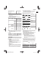
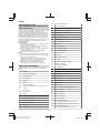
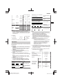
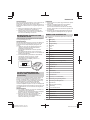
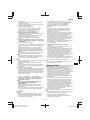
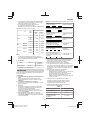
MOUNTING AND OPERATION
Action Figure Page
Removing and inserting the battery 3 3
Charging 4 3
Remaining battery indicator 36 10
Charging a USB device from a
electrical outlet 37-a 10
Charging a USB device and battery
from a electrical outlet 37-b 10
How to recharge USB device 38 10
Selecting accessories — 410,
411
PRIOR TO OPERATION
WARNING
Make all necessary adjustments before inserting the
batteries.
1. Battery
Do not use a battery other than that specified. Doing so
may result in damage or accidents.
2. Remove all packing materials attached or
connected to the tool before attempting to operate
it.
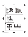
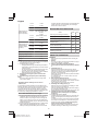
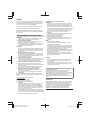
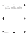
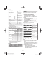
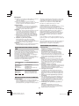
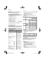
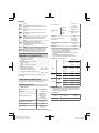
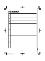
3. Installation (Fig.5)
Ensure that the machine is always fixed to bench.
Attach the power tool to a level, horizontal work bench.
Select 8mm diameter bolts suitable in length for the
thickness of the work bench.
Bolt length should be at least 40 mm plus the thickness
of the work bench.
For example, use 8mm × 65mm bolts for a 25mm
thick work bench.
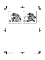
4. Base holder adjustment (Fig.6)
Loosen the 6mm bolt with the 10mm box wrench.
Adjust the base holder until its bottom surface contacts
the bench or the floor surface.
After adjustment, firmly tighten the 6mm bolt.
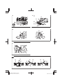
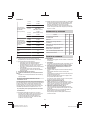
5. Releasing the locking pin (Fig.7)
When the power tool is prepared for shipping, its main
parts are secured by a locking pin.
Press the handle slightly down and pull out the locking
pin to disengag the cutting head.
During transport, lock the locking pin into the gear case.
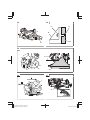
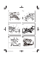
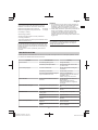
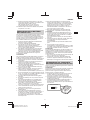
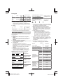
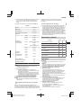
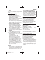
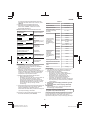
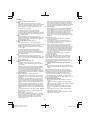
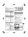
6. Installing the dust bag, sub table assembly,
stopper and vises (The stopper is an optional
accessory.)
(1) Installing the dust bag (Fig.8)
Install the dust bag onto the dust port on the miter saw.
Fit the connecting tube of dust bag and the dust port
together.
To empty the dust bag, pull out the dust bag assembly
from dust port. Open zipper on underside of bag and
empty into waste container. Check frequently and
empty the dust bag before it gets full.
When bevel angle cutting, adjust the support bar and
Install the dust bag so that it hangs down vertically.
2023/08/31 18:21:53Stylesheet: EU Version: 2023.8.18
C3612DRA_C99749371_309_EU
La pagina si sta caricando...
La pagina si sta caricando...
La pagina si sta caricando...
La pagina si sta caricando...
La pagina si sta caricando...
La pagina si sta caricando...
La pagina si sta caricando...
La pagina si sta caricando...
La pagina si sta caricando...
La pagina si sta caricando...
La pagina si sta caricando...
La pagina si sta caricando...
La pagina si sta caricando...
La pagina si sta caricando...
La pagina si sta caricando...
La pagina si sta caricando...
La pagina si sta caricando...
La pagina si sta caricando...
La pagina si sta caricando...
La pagina si sta caricando...
La pagina si sta caricando...
La pagina si sta caricando...
La pagina si sta caricando...
La pagina si sta caricando...
La pagina si sta caricando...
La pagina si sta caricando...
La pagina si sta caricando...
La pagina si sta caricando...
La pagina si sta caricando...
La pagina si sta caricando...
La pagina si sta caricando...
La pagina si sta caricando...
La pagina si sta caricando...
La pagina si sta caricando...
La pagina si sta caricando...
La pagina si sta caricando...
La pagina si sta caricando...
La pagina si sta caricando...
La pagina si sta caricando...
La pagina si sta caricando...
La pagina si sta caricando...
La pagina si sta caricando...
La pagina si sta caricando...
La pagina si sta caricando...
La pagina si sta caricando...
La pagina si sta caricando...
La pagina si sta caricando...
La pagina si sta caricando...
La pagina si sta caricando...
La pagina si sta caricando...
La pagina si sta caricando...
La pagina si sta caricando...
La pagina si sta caricando...
La pagina si sta caricando...
La pagina si sta caricando...
La pagina si sta caricando...
La pagina si sta caricando...
La pagina si sta caricando...
La pagina si sta caricando...
La pagina si sta caricando...
La pagina si sta caricando...
La pagina si sta caricando...
La pagina si sta caricando...
La pagina si sta caricando...
La pagina si sta caricando...
La pagina si sta caricando...
La pagina si sta caricando...
La pagina si sta caricando...
La pagina si sta caricando...
La pagina si sta caricando...
La pagina si sta caricando...
La pagina si sta caricando...
La pagina si sta caricando...
La pagina si sta caricando...
La pagina si sta caricando...
La pagina si sta caricando...
La pagina si sta caricando...
La pagina si sta caricando...
La pagina si sta caricando...
La pagina si sta caricando...
La pagina si sta caricando...
La pagina si sta caricando...
La pagina si sta caricando...
La pagina si sta caricando...
La pagina si sta caricando...
La pagina si sta caricando...
La pagina si sta caricando...
La pagina si sta caricando...
La pagina si sta caricando...
La pagina si sta caricando...
La pagina si sta caricando...
La pagina si sta caricando...
La pagina si sta caricando...
La pagina si sta caricando...
La pagina si sta caricando...
La pagina si sta caricando...
La pagina si sta caricando...
La pagina si sta caricando...
La pagina si sta caricando...
La pagina si sta caricando...
La pagina si sta caricando...
La pagina si sta caricando...
La pagina si sta caricando...
La pagina si sta caricando...
La pagina si sta caricando...
La pagina si sta caricando...
La pagina si sta caricando...
La pagina si sta caricando...
La pagina si sta caricando...
La pagina si sta caricando...
La pagina si sta caricando...
La pagina si sta caricando...
La pagina si sta caricando...
La pagina si sta caricando...
La pagina si sta caricando...
La pagina si sta caricando...
La pagina si sta caricando...
La pagina si sta caricando...
La pagina si sta caricando...
La pagina si sta caricando...
La pagina si sta caricando...
La pagina si sta caricando...
La pagina si sta caricando...
La pagina si sta caricando...
La pagina si sta caricando...
La pagina si sta caricando...
La pagina si sta caricando...
La pagina si sta caricando...
La pagina si sta caricando...
La pagina si sta caricando...
La pagina si sta caricando...
La pagina si sta caricando...
La pagina si sta caricando...
La pagina si sta caricando...
La pagina si sta caricando...
La pagina si sta caricando...
La pagina si sta caricando...
La pagina si sta caricando...
La pagina si sta caricando...
La pagina si sta caricando...
La pagina si sta caricando...
La pagina si sta caricando...
La pagina si sta caricando...
La pagina si sta caricando...
La pagina si sta caricando...
La pagina si sta caricando...
La pagina si sta caricando...
La pagina si sta caricando...
La pagina si sta caricando...
La pagina si sta caricando...
La pagina si sta caricando...
La pagina si sta caricando...
La pagina si sta caricando...
La pagina si sta caricando...
La pagina si sta caricando...
La pagina si sta caricando...
La pagina si sta caricando...
La pagina si sta caricando...
La pagina si sta caricando...
La pagina si sta caricando...
La pagina si sta caricando...
La pagina si sta caricando...
La pagina si sta caricando...
La pagina si sta caricando...
La pagina si sta caricando...
La pagina si sta caricando...
La pagina si sta caricando...
La pagina si sta caricando...
La pagina si sta caricando...
La pagina si sta caricando...
La pagina si sta caricando...
La pagina si sta caricando...
La pagina si sta caricando...
La pagina si sta caricando...
La pagina si sta caricando...
La pagina si sta caricando...
La pagina si sta caricando...
La pagina si sta caricando...
La pagina si sta caricando...
La pagina si sta caricando...
La pagina si sta caricando...
La pagina si sta caricando...
La pagina si sta caricando...
La pagina si sta caricando...
La pagina si sta caricando...
La pagina si sta caricando...
La pagina si sta caricando...
La pagina si sta caricando...
La pagina si sta caricando...
La pagina si sta caricando...
La pagina si sta caricando...
La pagina si sta caricando...
La pagina si sta caricando...
La pagina si sta caricando...
La pagina si sta caricando...
La pagina si sta caricando...
La pagina si sta caricando...
La pagina si sta caricando...
La pagina si sta caricando...
La pagina si sta caricando...
La pagina si sta caricando...
La pagina si sta caricando...
La pagina si sta caricando...
La pagina si sta caricando...
La pagina si sta caricando...
La pagina si sta caricando...
La pagina si sta caricando...
La pagina si sta caricando...
La pagina si sta caricando...
La pagina si sta caricando...
La pagina si sta caricando...
La pagina si sta caricando...
La pagina si sta caricando...
La pagina si sta caricando...
La pagina si sta caricando...
La pagina si sta caricando...
La pagina si sta caricando...
La pagina si sta caricando...
La pagina si sta caricando...
La pagina si sta caricando...
La pagina si sta caricando...
La pagina si sta caricando...
La pagina si sta caricando...
La pagina si sta caricando...
La pagina si sta caricando...
La pagina si sta caricando...
La pagina si sta caricando...
La pagina si sta caricando...
La pagina si sta caricando...
La pagina si sta caricando...
La pagina si sta caricando...
La pagina si sta caricando...
La pagina si sta caricando...
La pagina si sta caricando...
La pagina si sta caricando...
La pagina si sta caricando...
La pagina si sta caricando...
La pagina si sta caricando...
La pagina si sta caricando...
La pagina si sta caricando...
La pagina si sta caricando...
La pagina si sta caricando...
La pagina si sta caricando...
La pagina si sta caricando...
La pagina si sta caricando...
La pagina si sta caricando...
La pagina si sta caricando...
La pagina si sta caricando...
La pagina si sta caricando...
La pagina si sta caricando...
La pagina si sta caricando...
La pagina si sta caricando...
La pagina si sta caricando...
La pagina si sta caricando...
La pagina si sta caricando...
La pagina si sta caricando...
La pagina si sta caricando...
La pagina si sta caricando...
La pagina si sta caricando...
La pagina si sta caricando...
La pagina si sta caricando...
La pagina si sta caricando...
La pagina si sta caricando...
La pagina si sta caricando...
La pagina si sta caricando...
La pagina si sta caricando...
La pagina si sta caricando...
La pagina si sta caricando...
La pagina si sta caricando...
La pagina si sta caricando...
La pagina si sta caricando...
La pagina si sta caricando...
La pagina si sta caricando...
La pagina si sta caricando...
La pagina si sta caricando...
La pagina si sta caricando...
La pagina si sta caricando...
La pagina si sta caricando...
La pagina si sta caricando...
La pagina si sta caricando...
La pagina si sta caricando...
La pagina si sta caricando...
La pagina si sta caricando...
La pagina si sta caricando...
La pagina si sta caricando...
La pagina si sta caricando...
La pagina si sta caricando...
La pagina si sta caricando...
La pagina si sta caricando...
La pagina si sta caricando...
La pagina si sta caricando...
La pagina si sta caricando...
La pagina si sta caricando...
La pagina si sta caricando...
La pagina si sta caricando...
La pagina si sta caricando...
La pagina si sta caricando...
La pagina si sta caricando...
La pagina si sta caricando...
La pagina si sta caricando...
La pagina si sta caricando...
La pagina si sta caricando...
La pagina si sta caricando...
La pagina si sta caricando...
La pagina si sta caricando...
La pagina si sta caricando...
La pagina si sta caricando...
La pagina si sta caricando...
La pagina si sta caricando...
La pagina si sta caricando...
La pagina si sta caricando...
La pagina si sta caricando...
La pagina si sta caricando...
La pagina si sta caricando...
La pagina si sta caricando...
La pagina si sta caricando...
La pagina si sta caricando...
La pagina si sta caricando...
La pagina si sta caricando...
La pagina si sta caricando...
La pagina si sta caricando...
La pagina si sta caricando...
La pagina si sta caricando...
La pagina si sta caricando...
La pagina si sta caricando...
La pagina si sta caricando...
La pagina si sta caricando...
La pagina si sta caricando...
La pagina si sta caricando...
La pagina si sta caricando...
La pagina si sta caricando...
La pagina si sta caricando...
La pagina si sta caricando...
La pagina si sta caricando...
La pagina si sta caricando...
La pagina si sta caricando...
La pagina si sta caricando...
La pagina si sta caricando...
La pagina si sta caricando...
La pagina si sta caricando...
La pagina si sta caricando...
La pagina si sta caricando...
La pagina si sta caricando...
La pagina si sta caricando...
La pagina si sta caricando...
La pagina si sta caricando...
La pagina si sta caricando...
La pagina si sta caricando...
La pagina si sta caricando...
La pagina si sta caricando...
La pagina si sta caricando...
La pagina si sta caricando...
La pagina si sta caricando...
La pagina si sta caricando...
La pagina si sta caricando...
La pagina si sta caricando...
La pagina si sta caricando...
La pagina si sta caricando...
La pagina si sta caricando...
La pagina si sta caricando...
La pagina si sta caricando...
La pagina si sta caricando...
La pagina si sta caricando...
La pagina si sta caricando...
La pagina si sta caricando...
La pagina si sta caricando...
La pagina si sta caricando...
La pagina si sta caricando...
La pagina si sta caricando...
La pagina si sta caricando...
La pagina si sta caricando...
La pagina si sta caricando...
La pagina si sta caricando...
La pagina si sta caricando...
La pagina si sta caricando...
La pagina si sta caricando...
La pagina si sta caricando...
La pagina si sta caricando...
La pagina si sta caricando...
La pagina si sta caricando...
La pagina si sta caricando...
La pagina si sta caricando...
La pagina si sta caricando...
La pagina si sta caricando...
La pagina si sta caricando...
La pagina si sta caricando...
La pagina si sta caricando...
La pagina si sta caricando...
La pagina si sta caricando...
La pagina si sta caricando...
La pagina si sta caricando...
La pagina si sta caricando...
La pagina si sta caricando...
La pagina si sta caricando...
La pagina si sta caricando...
La pagina si sta caricando...
La pagina si sta caricando...
La pagina si sta caricando...
La pagina si sta caricando...
La pagina si sta caricando...
-
 1
1
-
 2
2
-
 3
3
-
 4
4
-
 5
5
-
 6
6
-
 7
7
-
 8
8
-
 9
9
-
 10
10
-
 11
11
-
 12
12
-
 13
13
-
 14
14
-
 15
15
-
 16
16
-
 17
17
-
 18
18
-
 19
19
-
 20
20
-
 21
21
-
 22
22
-
 23
23
-
 24
24
-
 25
25
-
 26
26
-
 27
27
-
 28
28
-
 29
29
-
 30
30
-
 31
31
-
 32
32
-
 33
33
-
 34
34
-
 35
35
-
 36
36
-
 37
37
-
 38
38
-
 39
39
-
 40
40
-
 41
41
-
 42
42
-
 43
43
-
 44
44
-
 45
45
-
 46
46
-
 47
47
-
 48
48
-
 49
49
-
 50
50
-
 51
51
-
 52
52
-
 53
53
-
 54
54
-
 55
55
-
 56
56
-
 57
57
-
 58
58
-
 59
59
-
 60
60
-
 61
61
-
 62
62
-
 63
63
-
 64
64
-
 65
65
-
 66
66
-
 67
67
-
 68
68
-
 69
69
-
 70
70
-
 71
71
-
 72
72
-
 73
73
-
 74
74
-
 75
75
-
 76
76
-
 77
77
-
 78
78
-
 79
79
-
 80
80
-
 81
81
-
 82
82
-
 83
83
-
 84
84
-
 85
85
-
 86
86
-
 87
87
-
 88
88
-
 89
89
-
 90
90
-
 91
91
-
 92
92
-
 93
93
-
 94
94
-
 95
95
-
 96
96
-
 97
97
-
 98
98
-
 99
99
-
 100
100
-
 101
101
-
 102
102
-
 103
103
-
 104
104
-
 105
105
-
 106
106
-
 107
107
-
 108
108
-
 109
109
-
 110
110
-
 111
111
-
 112
112
-
 113
113
-
 114
114
-
 115
115
-
 116
116
-
 117
117
-
 118
118
-
 119
119
-
 120
120
-
 121
121
-
 122
122
-
 123
123
-
 124
124
-
 125
125
-
 126
126
-
 127
127
-
 128
128
-
 129
129
-
 130
130
-
 131
131
-
 132
132
-
 133
133
-
 134
134
-
 135
135
-
 136
136
-
 137
137
-
 138
138
-
 139
139
-
 140
140
-
 141
141
-
 142
142
-
 143
143
-
 144
144
-
 145
145
-
 146
146
-
 147
147
-
 148
148
-
 149
149
-
 150
150
-
 151
151
-
 152
152
-
 153
153
-
 154
154
-
 155
155
-
 156
156
-
 157
157
-
 158
158
-
 159
159
-
 160
160
-
 161
161
-
 162
162
-
 163
163
-
 164
164
-
 165
165
-
 166
166
-
 167
167
-
 168
168
-
 169
169
-
 170
170
-
 171
171
-
 172
172
-
 173
173
-
 174
174
-
 175
175
-
 176
176
-
 177
177
-
 178
178
-
 179
179
-
 180
180
-
 181
181
-
 182
182
-
 183
183
-
 184
184
-
 185
185
-
 186
186
-
 187
187
-
 188
188
-
 189
189
-
 190
190
-
 191
191
-
 192
192
-
 193
193
-
 194
194
-
 195
195
-
 196
196
-
 197
197
-
 198
198
-
 199
199
-
 200
200
-
 201
201
-
 202
202
-
 203
203
-
 204
204
-
 205
205
-
 206
206
-
 207
207
-
 208
208
-
 209
209
-
 210
210
-
 211
211
-
 212
212
-
 213
213
-
 214
214
-
 215
215
-
 216
216
-
 217
217
-
 218
218
-
 219
219
-
 220
220
-
 221
221
-
 222
222
-
 223
223
-
 224
224
-
 225
225
-
 226
226
-
 227
227
-
 228
228
-
 229
229
-
 230
230
-
 231
231
-
 232
232
-
 233
233
-
 234
234
-
 235
235
-
 236
236
-
 237
237
-
 238
238
-
 239
239
-
 240
240
-
 241
241
-
 242
242
-
 243
243
-
 244
244
-
 245
245
-
 246
246
-
 247
247
-
 248
248
-
 249
249
-
 250
250
-
 251
251
-
 252
252
-
 253
253
-
 254
254
-
 255
255
-
 256
256
-
 257
257
-
 258
258
-
 259
259
-
 260
260
-
 261
261
-
 262
262
-
 263
263
-
 264
264
-
 265
265
-
 266
266
-
 267
267
-
 268
268
-
 269
269
-
 270
270
-
 271
271
-
 272
272
-
 273
273
-
 274
274
-
 275
275
-
 276
276
-
 277
277
-
 278
278
-
 279
279
-
 280
280
-
 281
281
-
 282
282
-
 283
283
-
 284
284
-
 285
285
-
 286
286
-
 287
287
-
 288
288
-
 289
289
-
 290
290
-
 291
291
-
 292
292
-
 293
293
-
 294
294
-
 295
295
-
 296
296
-
 297
297
-
 298
298
-
 299
299
-
 300
300
-
 301
301
-
 302
302
-
 303
303
-
 304
304
-
 305
305
-
 306
306
-
 307
307
-
 308
308
-
 309
309
-
 310
310
-
 311
311
-
 312
312
-
 313
313
-
 314
314
-
 315
315
-
 316
316
-
 317
317
-
 318
318
-
 319
319
-
 320
320
-
 321
321
-
 322
322
-
 323
323
-
 324
324
-
 325
325
-
 326
326
-
 327
327
-
 328
328
-
 329
329
-
 330
330
-
 331
331
-
 332
332
-
 333
333
-
 334
334
-
 335
335
-
 336
336
-
 337
337
-
 338
338
-
 339
339
-
 340
340
-
 341
341
-
 342
342
-
 343
343
-
 344
344
-
 345
345
-
 346
346
-
 347
347
-
 348
348
-
 349
349
-
 350
350
-
 351
351
-
 352
352
-
 353
353
-
 354
354
-
 355
355
-
 356
356
-
 357
357
-
 358
358
-
 359
359
-
 360
360
-
 361
361
-
 362
362
-
 363
363
-
 364
364
-
 365
365
-
 366
366
-
 367
367
-
 368
368
-
 369
369
-
 370
370
-
 371
371
-
 372
372
-
 373
373
-
 374
374
-
 375
375
-
 376
376
-
 377
377
-
 378
378
-
 379
379
-
 380
380
-
 381
381
-
 382
382
-
 383
383
-
 384
384
-
 385
385
-
 386
386
-
 387
387
-
 388
388
-
 389
389
-
 390
390
-
 391
391
-
 392
392
-
 393
393
-
 394
394
-
 395
395
-
 396
396
-
 397
397
-
 398
398
-
 399
399
-
 400
400
-
 401
401
-
 402
402
-
 403
403
-
 404
404
-
 405
405
-
 406
406
-
 407
407
-
 408
408
-
 409
409
-
 410
410
-
 411
411
-
 412
412
-
 413
413
-
 414
414
-
 415
415
-
 416
416
-
 417
417
-
 418
418
-
 419
419
-
 420
420


in altre lingue
- français: Hikoki C3612DRA Manuel utilisateur
- slovenčina: Hikoki C3612DRA Používateľská príručka
- dansk: Hikoki C3612DRA Brugermanual
- română: Hikoki C3612DRA Manual de utilizare