
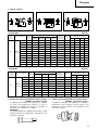
CORDLESS IMPACT WRENCH
AKKU-SCHLAGSCHRAUBER
CLÉ À CHOC À BATTERIE
AVVITATORE A PERCUSSIONE A BATTERIA
SNOERLOZE SLAGMOERAANZETTER
LLAVE DE IMPACTO A BATERÍA
CHAVE DE IMPACTO A BATERIA
ΜΠΥΛΝΚΛΕΙ∆ ΜΠΑΤΑΡΙΑΣ
Read through carefully and understand these instructions before use.
Diese Anleitung vor Benutzung des Werkzeugs sorgfältig durchlesen und verstehen.
Lire soigneusement et bien assimiler ces instructions avant usage.
Prima dell’uso leggere attentamente e comprendere queste istruzioni.
Deze gebruiksaanwijzing s.v.p. voor gebruik zorgvuldig doorlezen.
Leer
cuidadosamente y comprender estas instrucciones antes del uso.
Antes de usar, leia com cuidado para assimilar estas instruções.
∆ιαάστε πρσεκτικά και κατανήσετε αυτές τις δηγίες πριν τη ρήση.
Handling instructions
Bedienungsanleitung
Mode d’emploi
Istruzioni per l’uso
Gebruiksaanwijzing
Instrucciones de manejo
Instruções de uso
δηγίες ειρισµύ
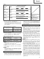
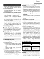
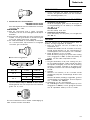
Variable speed
WR 12DM • WR 9DM

4
D
B
C>
>
E
F
B
123
5
6 7
8 9
>
A
B
1
1
3
2
3
4
1
3
6
5
7
1
9
8
G
(B)
(A)
H

10 11
2
12 13
14 15
M
N
L
3mm
11.5mm
I
R
K
K
L
J
O

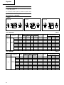
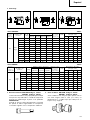
English Deutsch Français Italiano
1
2
3
4
5
6
7
8
9
0
A
B
C
D
E
F
G
H
I
J
K
L
M
N
O
12 V Rechargeable Akkumulator, 12 V Batterie rechargeable,
battery (For WR12DM) (Für WR12DM) 12 V (Pour WR12DM)
9.6 V Rechargeable Akkumulator, 9,6 V Batterie rechargeable,
battery (For WR9DM) (Für WR9DM) 9,6 V (Pour WR9DM)
Latch Schnapper Loquet
Handle Griff Poignée
Insert Einsatz Insérer
Pull out Herausziehen Tirer
Insert Einsetz Insérer
Pilot lamp Kontrollampe Lampe pilote
Hole for connecting the Anschlußlon für
Orifice de raccordement
rechargeable battery Akkumulator
de la batterie rechargeable
Hexagonal socket Sechskantbuchse Douille hexagonal
Groove Schlitz Rainure
Anvil Schabotte Chabotte
Pin Stift Goupille
Ring Ring Aunneau
Hole Öffnung Orifice
Plunger Preßkolben Piston
Convenient hook
Bequem zu
Crochet pratique
verwendender Haken
Spring Feder Ressort
Larger diameter faces Der große Durchmesser Gros diamètre dirigé
away weist zur anderen Seite vers l’extérieur
Push button Druckknopf Poussoir
Push Drücken Pousser
Wear limit Verschließgrenze Limite d'usure
Nail of carbon brush Klaue der Kohlebürste
Clou de balai en
carbone
Protrusion of carbon Krempe der Saillie de balai en
brush Kohlebürste carbone
Contact portion outside Kontaktteil außerhalb
Section de contact à
brush tube des Bürstenrohrs
l’extérieur du tube de balai
Batteria ricaricabile,
12 V (Per WR12DM)
Batteria ricaricabile,
9,6 V (Per WR9DM)
Fermo
Impugnatura
Inserire
Estrarre
Inserire
Spia
Foro di collegamento
della batería recargable
Chiave de incavo
esagonale
Scanalature
Basamento
Spina
Anello
Foro
Stantuffo
Gancio comodo
Molla
Diametro più grande
lontano da sé
Taste da premere
Spingere
Limite di usura
Chiodo di spazzola di
carbone
Sporgenza di spazzola
di carbone
Parte di contatto fuori
dal tubo spazzola
3

4
Nederlands Español Português Ελληνικά
1
2
3
4
5
6
7
8
9
0
A
B
C
D
E
F
G
H
I
J
K
L
M
N
O
Oplaadbare batterij, 12V Batería recargable, 12V
(Voor de WR12DM) (Para WR12DM)
Oplaadbare batterij, 9V Batería recargable, 9V
(Voor de WR9DM) (Para WR9DM)
Vergrendeling Enganche
Handgreep Mango
Insteken Insertar
Uittrekken Sacar
Insteken Insertar
Kontrolelampje Lámpara piloto
Aansluiting voor Agujero para conectar
oplaadbare batterij la batería recargable
Zeschoekige bus Recaptáculo hexanogal
Groef Ranura
Draaistuk Yunque
Pen Pasador
Ring Anillo
Opening Orificio
Plunjer Embolo
Handige haak Gancho conveniente
Veer Resorte
De grotere diameter
El diámetro más
wijst van u vandaan.
grande queda en
dirección opuesta
Druktoets Pulsador
Drukken Presionar
Slijtagegrens Límite de uso
Nagel van koolborstel
Uña de escobilla de
carbón
Uitsteeksel van Saliente de escobilla
koolborstel de carbón
Contact-gedeelte
Tubo exterior de la
buiten de borstelbuis
parte de contacto de
la escobilla de carbón
Bateria de 12 V
recarregável (Para WR12DM)
Bateria de 9,6 V
recarregável (Para WR9DM)
Lingüeta
Cabo
Inserir
Retirar
Inserir
Lâmpada piloto
Orifício para conectar a
bateria recarregável
Encaixe longo
Ranhura
Bigorna
Pino
Anel
Orifício
Pistão
Gancho conveniente
Mola
O diâmetro maior dá
para fora
Interruptor
Apertar
Limite de desgaste
Prego da escova de
carvão
Saliência da escova de
carvão
Segmento de contato
no exterior do tubo da
escova
12 V Επαναρτιµενη
µπαταρία (για τ WR12DM)
9,6 V Επαναρτιµενη
µπαταρία (για τ WR9DM)
Μάνδαλ
#ερύλι
Εισ&ωρήστε
Βρα*ή+τε έ+ω
Εισ&ωρήστε
∆κιµαστική λάµπα
Τρύπα για την σύνδεση
της επαναρτιµενης
µπαταρίας
Μακριά υπδ&ή
Αυλάκωση
Άκµνας
Πείρς
∆ακτύλις
Τρύπα
Έµ*λ
∆ιευκλυντικς
γάντς
Ελατήρι
Η µεγαλύτερη
διάµετρς *λέπει πρς
άλλη κατεύθυνση.
Κυµπί ώθησης
Σπρώ+ε
;ρι θράς
Καρί καρ*υνακιύ
Πρε+&ή
καρ*υνακιύ
Τµήµα επαής έ+ω
απ τ σωλήνα της
ψήκτρας

5
English
GENERAL OPERATIONAL PRECAUTIONS
1. Keep work area clean. Cluttered areas and benches
invite accidents.
2. Avoid dangerous environment. Don’t expose power
tools and charger to rain. Don’t use power tools
and charger in damp or wet locations. And keep
work area well lit. Never use power tools and
charger near flammable or explosive materials.
Do not use tool and charger in presence of
flammable liquids or gases.
3. Keep children away. All visitors should be kept
safe distance from work area.
4. Store idle tools and charger. When not in use,
tools and charger should be stored in dry, high
or locked-up place-out of reach of children. Store
tools and charger in a palce where the temperature
is less than 40˚C.
5. Don’t force tool. It will do the job better and safer
at the rate for which it was designed.
6. Use right tool. Don’t force small tool or attachment
to do the job of a heavy duty tool.
7. Wear proper apparel. Do not wear clothing or
jewelry. They can be caught in moving parts.
Rubber gloves and footwear are recommended
when working outdoor.
8. Use eye protection with most tools. Also use face
or dust mask if cutting operation is dusty.
9. Don’t abuse cord. Never carry charger by cord or
yank it to disconnect from receptacle. Keep cord
from heat, oil and sharp edges.
10. Secure work. Use clamps or a vise to hold work.
It’s safer than using your hand and it frees both
hands to operate tool.
11. Don’t overreach. Keep proper footing and balance
at all times.
12. Maintain tools with care. Keep tools sharp at all
times, and clean for best and safest performance.
Follow instructions for lubricating and changing
accessories.
13. When the charger is not in use, or when being
maintained and inspected, disconnect its power
cord from the AC outlet.
14. Remove chuck wrenches and wrenches. Form habit
of checking to see that wrenches are removed
from tool before turning it on.
15. Avoid accidental starting. Don’t carry tool with
finger on switch.
16. To avoid danger, always use only the specified
charger.
17. Use only original HITACHI replacement parts.
18. Do not use power tools for applications other than
those specified in the Handling Instructions.
19. To avoid personal injury, use only the accessories
or attachment recommended in these handling
instructions or in the HITACHI catalog.
20. If the supply cord of this charger is damaged, the
charger must be returned to the HITACHI
authorized service center for the cord to be
replaced. Let only the authorized service center
do the repairing. The Manufacturer will not be
responsible for any damages or injuries caused
by repair by the unauthorized persons or by
mishandling of the tool.
21. To ensure the designed operational integrity of
power tools and charger, do not remove installed
covers or screws.
22. Always use the charger at the voltage specified
on the nameplate.
23. Do not touch movable parts or accessories unless
the battery has been removed.
24. Always charge the battery before use.
25. Never use a battery other than that specified. Do
not connect a usual dry cell, a rechargeable battery
other than that specified or a car battery to the
power tool.
26. Do not use any transformer that has a booster.
27. Do not charge the battery from an engine electric
generator or DC power supply.
28. Always charge indoors. Because the charger and
battery heat slightly during charging, charge the
battery in a place not exposed to direct sunlight;
where the humidity is low and the ventilation
good.
29. When working in a high place, pay attention to
the activities below to make sure there are no
people below.
30. Use the exploded assembly drawing on this
handling instructions only for authorized servicing.
PRECAUTIONS FOR CORDLESS IMPACT
WRENCH
1. This is a portable tool for tightening and loosening
bolts and nuts. Use it only for these operation.
2. Use the earplugs if using for a long time.
3. One-hand operation is extremely dangerous; hold
the unit firmly with both hands when operating.
4. Check that the socket is not cracked or broken.
Broken or cracked sockets are dangerous. Check
the socket before using it.
5. Secure the socket with the socket pin and the ring.
If the socket pin or ring securing the socket is
damaged, the socket may come off from the impact
wrench, which is quite dangerous. Do not use
socket pins or rings that are deformed, worn out,
cracked, or in any other way damaged. Always
make sure to install the socket pin and ring in
the correct position.
6. Check the tightening torque.
The appropriate torque for tightening a bolt
depends on the material the bolt is made of, its
dimensions, grade, etc.
Also, the tightening torque generated by this
impact wrench depends on the materials and
dimensions of the bolt, how long the impact
wrench is applied for the way in which the socket
is installed, etc.
Also the torque when the battery has just been
charged and when it is about to run out are
slightly different. Use a torque wrench to check
that the bolt has been tightened with the
appropriate torque.
7. Stop the impact wrench before switching the
direction of rotation. Always release the switch
and wait for impact wrench to stop before
switching the direction of rotation.
8. Never touch the turning part.
Do not allow the turning socket section to get near
your hands or any other part of your body. You
could be cut or caught in the socket. Also, be
careful not to touch the socket after using
continuously it for a long time. It gets quite hot
and could burn you.
9. Never let the impact wrench turn without a load
when using the universal joint.
If the socket turns without being connected to a
load, the universal joint causes the socket to turn
wildly.
You could get hurt or the movement of the socket
could shake the impact wrench so much as to
make you drop it.
10. Always charge the battery at a temperature of 0
– 40°C.
A temperature of less than 0°C will result in over
charging which is dangerous. The battery cannot
be charged at a temperature greater than 40°C.
The most suitable temperature for charging is that
of 20 – 25°C.

6
English
11. Do not use the charger continuously.
When one charging is completed, leave the charger
for about 15 minutes before the next charging of
battery.
12. Do not allow foreign matter to enter the hole for
connecting the rechargeable battery.
13. Never disassemble the rechargeable battery and
charger.
14. Never short-circuit the rechargeable battery.
Short-circuiting the battery will cause a great
electric current and overheat. It results in burn or
damage to the battery.
15. Do not dispose of the battery in fire.
If the battery burnt, it may explode.
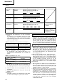
SPECIFICATIONS
POWER TOOL
16. Do not insert object into the air ventilation slots
of the charger.
Inserting metal objects or inflammables into the
charger air ventilation slots will result in electrical
shock hazard or damaged charger.
17. Bring the battery to the shop from which it was
purchased as soon as the post-harging battery life
becomes too short for practical use. Do not dispose
of the exhausted battery.
18. Using an exhausted battery wil damage the
charger.
MODEL
WR12DM: with charger and case
WR9DM: with charger and case
Model WR9DM WR12DM
(9.6 V) (12 V)
No-load speed 0 – 2.300 min
–1
(/min)
Angle driver 9.5 mm 12.7 mm
Capacity M6 – M14 (Ordinary bolt) M6 – M16 (Ordinary bolt)
M6 – M10 (High tension bolt) M6 – M12 (High tension bolt)
Tightening torque
Rechargeable battery EB9B (2.0 Ah) EB1220BL (2.0 Ah)
Ni-Cd battery, 9.6 V Ni-Cd battery, 12 V
EB930H (3.0 Ah) EB1230HL (3.0 Ah)
Ni-MH battery, 9.6 V Ni-MH battery, 12 V
Weight 1.4 kg 1.6 kg
Maximum 88.2 N·m
{900 kgf·cm}
Tightening is M12 high tension bolt
(strength grade 12.9), when fully
charged at 20°C temp.
Tightening time: 3 sec.
Maximum 150 N·m
{1530 kgf·cm}
Tightening is M16 (F10T), when fully
charged at 20°C temp.
Tightening time: 3 sec.
STANDARD ACCESSORIES
1. Charger (UC14YF2) ................................................... 1
2. Plastic case ................................................................ 1
Standard accessories are subject to change without
notice.
CHARGER
Model UC14YF2
Charging time EB9B: Approx. 60 min. (at 20°C) EB1220BL: Approx. 60 min. (at 20°C)
EB930H: Approx. 90 min. (at 20°C) EB1230HL: Approx. 90 min. (at 20°C)
Charging voltage 7.2 – 14.4 V
Weight 1.3 kg

7
English
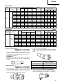
OPTIONAL ACCESSORIES
(Sold separately)
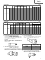
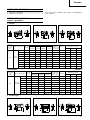
1. Sockets
Form B Form C
Form D
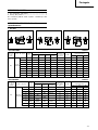
<For WR12DM> Table 1
Code No.
High ISO ISO Inch
Form
tension
(ordinary)
(small) bolts L L1 øF
10 mm 944291 M6 10 B 40 8 18
12 mm 873632 M8 W5/16" 12 B 40 8 20
13 mm 873539 M8 13 B 40 9 25
12.7
14 mm 873540 M10 14 B 40 9 25
17 mm 873536 M10 M12 W3/8" 17 C 32 8 28
19 mm 873624 M12 M14 W7/16" 19 C 34 9 28
21 mm 873626 W1/2" 21 D 36 10 32
22 mm 873627 M12 M14 M16 22 D 40 14 35
24 mm 873629 M16 M18 24 D 40 15 38
Square
head drive
dimensions
S (mm)
Part Name
Suitable Bolt Diameter
Hexagonal
width across
flats H (mm)
Main Socket
Dimensions (mm)
Hexagonal
Socket
Form B Form C
Form D
2. Long Socket
H S
L1
L2
L
ØF
H
S
L1
L2
L
ØF
H S
L
L1
ØF
H S
L
L1
ØF
H S
L
L1
ØF
H
S
L1
L2
L
ØF
<For WR9DM> Table 2
Code No.
ISO ISO Inch
Form
(ordinary)
(small) bolts L L1 øF
8 mm 996125 M5 8 B 33 5 13
10 mm 996126 M6 10 B 33 6 16
12 mm 996127 M8 W5/16" 12 C 33 7 19
9.5
13 mm 996128 M8 13 B 33 8 20
14 mm 996129 M10 14 B 33 8 21
16 mm 996130 M10 16 D 33 9 24
17 mm 996131 M10 M12 W3/8" 17 D 33 10 25
18 mm 996132 M12 18 D 33 10 26
19 mm 996133 M12 W7/16" 19 D 33 12 27.5
Square
head drive
dimensions
S (mm)
Part Name
Suitable Bolt Diameter
Hexagonal
width across
flats H (mm)
Main Socket
Dimensions (mm)
Hexagonal
Socket

8
English
3. Extension bar: WR12DM: Code No. 873633
WR9DM: Code No. 996143
The extension bar is convenient for working in very
restricted spaces or when the socket provided cannot
reach the bolt to be tightened.
CAUTION
when the extension bar is used, the tightening
torque is reduced slightly compared with the
ordinary socket.
4. Universal joint:WR12DM: Code No. 992610
WR9DM: Code No. 996147
The universal joint is convenient for impacting nuts
when there is an angle between the socket and
wrench, or when working in a very narrow space.
5. Duct Socket: (WR12DM)
This is used for tightening bolts and nuts on flange
sections of air conditioners, type ducts, etc.
6. Corner attachment (Model EW-14R)(WR12DM)
Use this attachment only when the machine is
applied to the nut or bolt at the right angle.
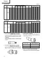
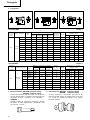
<For WR12DM> Table 3
Code No.
High ISO ISO Inch
Form
tension
(ordinary)
(small) bolts L L1 L2 øF
12 mm 955138 M8 W5/16" 12 B 52 20 34 20
13 mm 955139 M8 13 B 52 20 34 21.5
14 mm 955140 M10 14 B 52 20 34 22
17 mm 955141 M10 M12 W3/8" 17 B 52 24 34 25
17 mm 955149 M10 M12 W3/8" 17 B 75 24 57 25
12.7 19 mm 955142 M12 M14 W7/16" 19 B 52 24 34 28
19 mm 955150 M12 M14 W7/16" 19 B 75 24 57 28
21 mm 955143 W1/2" 21 D 52 24 34 31
21 mm 955151 W1/2" 21 D 75 24 57 31
21 mm 991480 W1/2" 21 D 125 24 107 31
22 mm 955144 M12 M14 M16 22 D 52 24 34 32.5
24 mm 955146 M16 M18 24 D 52 25 34 34
Square
head drive
dimensions
S (mm)
Part Name
Suitable Bolt Diameter
Hexagonal
width across
flats H (mm)
Main Socket
Dimensions (mm)
Long
Socket
<For WR9DM> Table 4
Code No.
ISO ISO Inch
Form
(ordinary)
(small) bolts L L1 L2 øF
8 mm 996134 M5 8 B 60 12 48 13
10 mm 996135 M6 10 B 60 12 48 16
12 mm 996136 M8 W5/16" 12 C 60 14 48 18.4
9.5
13 mm 996137 M8 13 B 60 14 48 18.9
14 mm 996138 M10 14 B 60 15 48 19.5
16 mm 996139 M10 16 D 60 15 48 24
17 mm 996140 M10 M12 W3/8" 17 D 60 15 48 25
18 mm 996141 M12 18 D 60 16 48 26
19 mm 996142 M12 W7/16" 19 D 60 17 48 27.5
Square
head drive
dimensions
S (mm)
Part Name
Suitable Bolt Diameter
Hexagonal
width across
flats H (mm)
Main Socket
Dimensions (mm)
Long
Socket
Code No.
Hexagonal width
across flats (mm)
993658 12
992613 13
992615 14

9
English
L 6.35
Bit No. L (mm) Code No.
No. 2
45 955229
70 955654
No. 3
45 955230
70 955655
Bit No.
8. 12.7 mm Square adaptor: WR9DM: Code No. 996145
This is used when using a socket with square hole
dimensions of 12.7 mm.
Optional accessories are subject to change without
notice.
APPLICATION
䡬 Tightening and loosening of all types of bolts and
nuts, used for securing structural items.
7. Bit adaptor: WR12DM: Code No. 991476
WR9DM: Code No. 996144
This is used for tightening small screws (M6 – M8).
NOTES
(1) This adaptor is set only on the anvil (drive angle)
of the main unit. The bit adapter cannot be attached
to the special accessory anvil (square drive).
(2) Before starting work with the adapter, tighten a few
screws with it to make sure it’s tightening with the
appropriate torque.
(3) Tightening speed will be greatly reduced when
driving wood, tapping or other similar screws.
䢇 Applicable plus driver bit
BATTERY REMOVAL/INSTALLATION
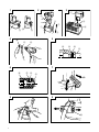
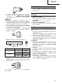
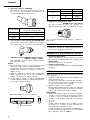
1. Battery removal
Hold the hadle tightly and push the battery latch
to remove the battery. (Figs. 1 and 2)
CAUTION
Never short-circuit the battery.
2. Battery installation
Insert the battery while observing its polarities (see
Fig. 2).
CHARGING
Before using the impact wrench, charge the battery as
follows.
1. Connect the charger’s power cord to a receptacle.
When the power cord is connected, the charger’s
pilot lamp will blink in red. (At 1-second intervals).
2. Insert the battery into the charger.
Insert the battery firmly, in the direction shown in
Fig. 3, until it contacts the bottom of the charger
compartment.
CAUTION
䡬 If the battery is inserted in the reverse direction,
not only recharging will become impossible, but it
may also cause the fuse to blow, or problems in
the charger such as deformed recharging terminal.
3. Charging
When inserting a battery in the charger, charging
will commence and the pilot lamp will light
continuously in red.
When the battery becomes fully recharged, the pilot
lamp will blink in red. (At 1-second intervals.) (See
Table 5)
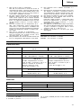
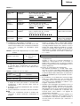
(1) Pilot lamp indication
The indications of the pilot lamp will be as shown
in Table 5, according to the condition of the charger
or the rechargeable battery.

10
English
Table 5
Indications of the lamps
Lights for 0.5 seconds. Does not light for
0.5 seconds. (off for 0.5 seconds)
Lights continuously
Lights for 0.5 seconds. Does not light for
0.5 seconds. (off for 0.5 seconds)
Lights for 0.1 seconds. Does not light for
0.1 seconds. (off for 0.1 seconds)
Lights continuously
Before
charging
While
charging
Charging
complete
Charging
impossible
Charging
impossible
Blinks
(RED)
Lights
(RED)
Blinks
(RED)
Flickers
(RED)
Lights
(GREEN)
Malfunction in the battery
or the charger
The battery temperature
is high, making recharg-
ing impossible.
(2) Regarding the temperatures of the rechargeable
battery.
The temperatures for rechargeable batteries are as
shown in the table below, and batteries that have
become hot should be cooled for a while before
being recharged.
Table 6 Recharging ranges of batteries
(3) Regarding recharging time
Depending on the combination of the charger and
batteries, the charging time will become as shown
in Table 7.
Table 7 Charging time (At 20°C)
NOTE
The charging time may vary according to
temperature and power source voltage.
4. Disconnect the charger’s power cord from the
receptaele.
5. Hold the charger firmly and pull out the battery.
NOTE
After charging, pull out batteries from the charger
first, and then keep the batteries properly.
Regarding electric discharge in case of new batteries,
etc.
As the internal chemical substance of new batteries
and batteries that have not been used for an
extended period is not activated, the electric
Temperatures at
Rechargeable batteries which the battery
can be recharged
EB9B, EB1220BL –5°C – 60°C
EB930H, EB1230HL 0°C – 45°C
Charger
UC14YF2
Battery
EB9B, EB1220BL Approx. 60 min.
EB930H, EB1230HL Approx. 90 min.
discharge might be low when using them the first
and second time. This is a temporary phenomenon,
and normal time required for recharging will be
restored by recharging the batteries 2 – 3 times.
How to make the batteries perform longer.
(1) Recharge the batteries before they become
completely exhausted.
When you feel that the power of the tool becomes
weaker, stop using the tool and recharge its battery.
If you continue to use the tool and exhaust the
electric current, the battery may be damaged and
its life will become shorter.
(2) Avoid recharging at high temperatures.
A rechargeable battery will be hot immediately after
use. If such a battery is recharged immediately after
use, its internal chemical substance will deteriorate,
and the battery life will be shortened. Leave the
battery and recharge it after it has cooled for a
while.
CAUTION
䡬 If the battery has been heated right after operation
(or due to sunlight, etc.), the charger’s pilot lamp
may not light in red. In such a case, first let the
battery cool, then start charging.
䡬 When the pilot lamp flickers in red quickly (at 0.2-
second intervals), check for and take out any foreign
objects in the charger’s battery installation hole. If
there are no foreign objects, it is probable that the
battery or charger is malfunctioning. Take it to your
Authorized Service Center.
䡬 Since the built-in micro computer takes about 3
seconds to confirm that the battery being charged
with UC14YF2 is taken out, wait for a minimum of
3 seconds before reinserting it to continue charging.
If the battery is reinserted within 3 seconds, the
battery may not be properly charged.
PRIOR TO OPERATION
1. Preparing and checking the work environment
Make sure that the work site meets all the conditions
laid forth in the precautions.

11
English
The L-side of the push button is pushed to turn the
bit counterclockwise. (See Fig. 11). (The
L
and
R
marks are engraved on the body.)
CAUTION
The push button can not be switched while the
impact driver is turning. To switch the push button,
stop the impact driver, then set the push button.
3. Switch operation
䡬 When the trigger switch is depressed, the tool
rotates. When the trigger is released, the tool stops.
䡬 The rotational speed can be controlled by varying
the amount that the trigger switch is pulled. Speed
is low when the trigger switch is pulled slightly and
increases as the trigger switch is pulled more.
4. Tightening and loosening bolts
A hex socket matching the bolt or nut must first
be selected. Then mount the socket on the anvil,
and grip the nut to be tightened with the hex socket.
Holding the wrench in line with the bolt, press the
power switch to impact the nut for several seconds.
If the nut is only loosely fitted to the bolt, the bolt
may turn wit the nut, therefore mistaking proper
tightening. In this case, stop impact on the nut and
hold the bolt head with a wrench before restarting
impact, or manually tighten the bolt and nut to
prevent them slipping.
5. Number of bolt tightened possible
Please refer to the table below for the number of
bolt tightened possible with one charge.
For WR12DM (EB1230HL)
For WR9DM (EB930H)
These values may vary slightly, according to
surrounding temperature and battery characteristics.
NOTE
The use of the battery EB1230HL and EB930H in
a cold condition (below 0 degree Centigrade) can
sometimes result in the weakened tightening torque
and reduced amount of work. This, however, is a
temporary phenomenon, and returns to normal when
the battery warms up.
OPERATIONAL CAUTIONS
1. Resting the unit after continuous work
After use for continuous bolt-tightening work, rest
the unit for 15 minutes or so when replacing the
battery. The temperature of the motor, switch, etc.,
will rise if the work is started again immediately
after battery replacement, eventually resulting in
burnout.
NOTE:
Do not touch the hammer case, as it gets very hot
during continuous work.
Bolt used No. of tightenings
M16 × 55 (F10T) Approx. 135
2. Checking the battery
Make sure that the battery is installed firmly. If it
is at all loose it could come off and cause an
accident.
3. Selecting the socket matched to the bolt
Be sure to use a socket which is matched to the
bolt to be tightened. Using an improper socket will
not only result in insufficient tightening but also in
damage to the socket or nut.
A worn or deformed hex. or square-holed socket
will not give an adequate tightness for fitting to the
nut or anvil, consequently resulting in loss of
tightening torque.
Pay attention to wear of socket hole, and replace
before further wear has developed.
Finally, install the socket prescribed in Item 4. The
section on “Optional Accessories” details the
relationship between bolt sizes and sockets. Sockets
are named according to the dihedral width of the
hexagonal hole.
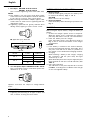
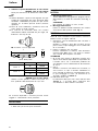
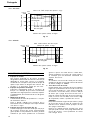
4. Installing a socket
Select the socket to be used.
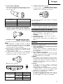
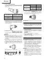
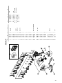
䢇 Pin, O-ring type (Fig. 4 and 5)
(1) Align the hole in the socket with the hole in the
anvil and insert the anvil into the socket.
(2) Insert the pin into the socket.
(3) Attach the ring to the groove on the socket.
䢇 Plunger type (Fig. 6)
Align the plunger located in the square part of the
anvil with the hole in the hex. socket. Then push
the plunger, and mount the hex. socket on the anvil.
Check that the plunger is fully engaged in the hole.
When removing the socket, reverse the sequence.
HOW TO USE
1. Using the convenient hook
The convenient hook can be installed on the right
or left side and the angle can be adjusted in 5 steps
between 0° and 80°.
(1) Operating the hook
(a) Pull out the hook toward you in the direction
of arrow (A) and turn in the direction of arrow
(B). (Fig. 7)
(b) The angle can be adjusted in 5 steps (0°, 20°,
40°, 60°, 80°).
Adjust the angle of the hook to the desired
position for use.
(2) Switching the hook position
CAUTION:
Incomplete installation of the hook may result in
bodily injury when used.
(a) Securely hold the main unit and remove the
screw using a slotted head screwdriver or a
coin. (Fig. 8)
(b) Remove the hook and spring. (Fig. 9)
(c) Install the hook and spring on the other side and
securely fasten with screw. (Fig. 8)
NOTE:
Pay attention to the spring orientation. Install the
spring with larger diameter away from you. (Fig.
10)
2. Check the rotational direction
The bit rotates clockwise (viewed from the rear
side) by pushing the R-side of the push button.
Bolt used No. of tightenings
High tension bolt
Approx. 135
M12 × 45

12
English
2. Cautions on use of the speed control switch
This switch has a built-in, electronic circuit which
steplessly varies the rotation speed. Consequently,
when the switch trigger is pulled only slightly (low
speed rotation) and the motor is stopped while
continuously driving in screws, the components of
the electronic circuit parts may overheat and be
damaged.
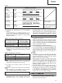
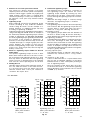
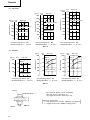
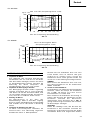
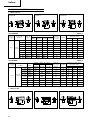
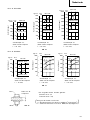
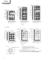
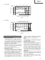
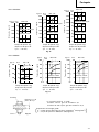
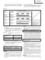
3. Tightening torque
Refer to Fig. 16 and 17 for the tightening torque
of bolts (according to size), under the conditions
shown in Fig. 18. Please use this example as a
general reference, as tightening torque will vary
according to tightening conditions.
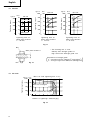
Tightening torque varies, depending on the battery’s
charge level. Fig. 19 and 20 shows an example of
the relationship between tightening torque and the
number of tightenings, for WR12DM and WR9DM.
As shown, tightening torque gradually weakens with
the increase in the number of tightenings. In
particular, as the torque decreases very close to the
complete discharge (“a” margin in graph), the unit’s
impact weakens, the number of time impacts
declines and tightening torque drops off abruptly.
If this occurs, check torque level, then recharge the
battery if necessary.
4. Work at a tightening torque suitable for the bolt
under impact
The optimum tightening torque for nuts or bolts
differs with material and size of the nuts or bolts.
An excessively large tightening torque for a small
bolt may stretch or break the bolt. The tightening
torque increases in proportionate to the operaton
time. Use the correct operating time for the bolt.
5. Holding the tool
Hold the impact wrench firmly with both hands. In
this case hold the wrench in line with the bolt.
It is not necessary to push the wrench very hard.
Hold the wrench with a force just sufficient to
counteract the impact force.
6. Confirm the tightening torque
The following factors contribute to a reduction of
the tightening torque. So confirm the actual
tightening torque needed by screwing up some
bolts before the job with a hand torque wrench.
Factors affecting the tightening torque are as follows.
(1) Voltage
When the discharge margin is reached, voltage
decreases and tightening torque is lowered.
(2) Operating time
The tightening torque increases when the operating
time increases. But the tightening torque does not
increase above a certain value even if the tool is
driven for a long time. (See Fig. 16 and 17)
(3) Diameter of bolt
The tightening torque differs with the diameter of
the bolt as shown in Fig. 16 and 17. Generally a
larger diameter bolt requires larger tightening torque.
(4) Tightening conditions
The tightening torque differs according to the torque
ratio; class, and length of bolts even when bolts
with the same size threads are used. The tightening
torque also differs according to the condition of the
surface of workpiece through which the bolts are
to be tightened. When the bolt and nut turn together,
torque is greatly reduced.
(5) Using optional parts
The tightening torque is reduced a little when an
extension bar, universal joint or a long socketis
used.
(6) Clearance of the socket
A worn or deformed hex or a square-holed socket
will not give an adequate tightness to the fitting
between the nut or anvil, consequently resulting in
loss of tightening torque.
Using an improper socket which does not match
to the bolt will result in an insufficient tightening
torque. Matching socket and bolt sizes are shown
in Table 1, 2, 3 and 4.
Tightening time: sec
(Steel plate thickness
t = 10 mm)
Tightening time: sec
(Steel plate thickness
t = 25 mm)
Tightening time: sec
(Steel plate thickness
t = 25 mm)
Tightening torque
M10 × 30
kgf•cm
1000
800
600
400
200
0
0 1
2
3
N•m
100
80
60
40
20
0
High tension bolt
Ordinary bolt
M12 × 45
kgf•cm
1400
1200
1000
800
600
400
200
0
0 1
2
3
N•m
140
120
100
80
60
40
20
0
Tightening torque
High tension bolt
Ordinary bolt
M14 × 50
kgf•cm
1600
1400
1200
1000
800
600
400
200
0
0 1
2
3
N•m
160
140
120
100
80
60
40
20
0
Tightening torque
High tension bolt
Ordinary bolt
<For WR12DM>
Fig. 16

13
English
Tightening torque
Number of tightenings (PCS)/charging
kgf•cm
1600
1200
800
400
0
0
20
40
60
80
100 120 140
N•m
160
120
80
40
0
a
When full recharged
When completely discharged
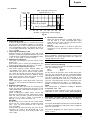
Explanation of strength grade:
4 — Yield point of bolt: 320 N/mm
2
{32.6 kgf/mm
2
}
8 — Pulling strength of bolt: 400 N/mm
2
{40.8 kgf/mm
2
}
* The following bolt is used.
Ordinary bolt: Strength grade 4.8
High tensile bolt: Strength grade 12.9
(
Bolt
Nut
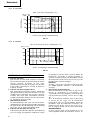
Fig. 18
Steel plate thickness t
)
Tightening time: sec
(Steel plate thickness
t = 10 mm)
Tightening time: sec
(Steel plate thickness
t = 10 mm)
Tightening time: sec
(Steel plate thickness
t = 25 mm)
M8 × 30
kgf•cm
800
600
400
200
0
N•m
80
60
40
20
0
0
1 2 3
High tension bolt
Ordinary bolt
M10 × 30
kgf•cm
1000
800
600
400
200
0
N•m
100
80
60
40
20
0
0
1 2 3
High tension bolt
Ordinary bolt
M12 × 45
kgf•cm
1000
800
600
400
200
0
N•m
100
80
60
40
20
0
0
1 2 3
High tension
bolt
Ordinary bolt
<For WR9DM>
Fig. 17
<For WR12DM>
Fig. 19
M16 × 55 F10T (tighening time 3 sec)
Tightening torque
Tightening torque
Tightening torque

14
English
<For WR9DM>
Fig. 20
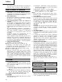
MAINTENANCE AND INSPECTION
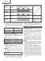
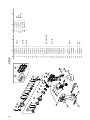
1. Inspecting the socket
A worn or deformed hex or a square-holed socket
will not give an adequate tightness to the fitting
between the nut or anvil, consequently resulting in
loss of tightening torque. Pay attention to wear of
a socket holes periodically, and replace with a new
one if needed.
2. Inspecting the mounting screws
Regularly inspect all mounting screws and ensure
that they are properly tightened. Should any of the
screws be loose, retighten them immediately. Failure
to do so may result in serious hazard.
3. Maintenance of the motor
The motor unit winding is the very "heart" of the
power tool.
Exercise due care to ensure the winding does not
become damaged and/or wet with oil or water.
4. Inspecting the carbon brushes (Fig. 12)
The motor employs carbon brushes which are
consumable parts. Since and excessively worn
carbon brush can result in motor trouble, replace
the carbon brush with new ones when it becomes
worn to or near the "wear limit". In addition, always
keep carbon brushes clean and ensure that they
slide freely whthin the brush holders
NOTE:
When replacing the carbon brush with a new one,
be sure to use the Hitachi Carbon Brush Code No.
999054.
5. Replacing carbon brushes
Take out the carbon brush by first removing the
brush cap and then hooking the protrusion of the
carbon brush with a flat head screw driver, etc., as
shown in Fig. 14.
When installing the carbon brush, choose the
direction so that the nail of the carbon brush agrees
with the contact portion outside the brush tube.
Then push it in with a finger as illustrated in
Fig. 15. Lastly, install the brush cap.
CAUTION:
Be absolutely sure to insert the nail of the carbon
brush into the contact portion outside the brush
tube. (You can insert whichever one of the two
nails provided.)
Caution must be exercised since any error in this
operation can result in the deformed nail of the
carbon brush and may cause motor trouble at an
early stage.
6. Cleaning of the outside
When the impact wrench is stained, wipe with a
soft dry cloth or a cloth moistened with soapy
water. Do not use chloric solvents, gasoline or paint
thinner, as they melt plastics.
7. Storage
Store the impact wrench in a place in which the
temperature is less than 40°C, and out of reach of
children.
NOTE
Due to HITACHI’s continuing program of reserch and
development, the specifications herein are subject to
change without prior notice.
IMPORTANT
Correct connection of the plug
The wires of the mains lead are coloured in accordance
with the following code:
Blue: –Neutral
Brown: –Live
As the colours of the wires in the mains lead of this
tool may not correspond with the coloured markings
identifying the terminals in your plug proceed as follows:
The wire coloured blue must be connected to the
terminal marked with the letter N or coloured black.
The wire coloured brown must be connected to the
terminal marked with the letter L or coloured red.
Neither core must be connected to the earth terminal.
NOTE
This requirement is provided according to BRITISH
STANDARD 2769: 1984.
Therefore, the letter code and colour code may not be
applicable to other markets except United Kingdom.
Information concerning airborne noise and vibration
The measured values were determined according to
EN50144.
The typical A-weighted sound pressure level: 97 dB (A)
The typical A-weighted sound power level: 110 dB (A)
Wear ear protection.
The typical weighted root mean square acceleration
value: 12 m/s
2
kgf•cm
1600
1200
800
400
0
0
20 40
60
80 100 120 140 160
N•m
160
120
80
40
0
a
Tightening torque
Number of tightenings (PCS)/charging
When full recharged
When completely discharged
M14 × 50 High tension bolt
(tighening time 3 sec)

15
Deutsch
VORSICHT FÜR ALLGEMEINE BEDIENUNG
1. Den Arbeitsplatz stets sauber halten.
Unaufgeräumte Arbeitsplätze und Werkbänke
erhöhen die Unfallgefahr.
2. Gefährliche Umgebungen vermeiden. Die Maschine
und das Ladegerät keiner Feuchtigkeit aussetzen
oder an nassen Stellen benutzen.
Achten Sie auf einen hellen, wenn erforderlich gut
beleuchteten Arbeitsplatz. Maschine und Ladegerät
niemals in der Nähe von brennbaren oder
explosiven Materialien, Flüssigkeiten oder Gasen
verwenden.
3. Außer Reichweite von Kindern halten. Nicht an
der Arbeit beteiligte Personen sollten einen
Sicherheitsabstand einhalten.
4. Unbenutztes Werkzeug und Ladegerät an einen
trockenen und verschlossenen Ort wegräumen;
außerhalb der Reichweite von Kindern
aufbewahren.
Die Temperatur sollte weniger als 40˚C betragen.
5. Das Werkzeug nicht überlasten. Es arbeitet sich
besser und sicherer bei angemessenen
Geschwindigkeiten und Belastungen.
6. Das richtige Werkzeug zur Arbeit verwenden.
Erwarten Sie nicht, daß ein zu kleines Werkzeug
oder Zubehör die Arbeit einer
Hochleistungsmaschine verrichtet.
7. Achten Sie auf die richtige Kleidung. Lose oder
zu weite Kleidung bzw. und/oder Schmuck (z.B.
Ketten, Ringe, usw.) könnten sich in rotierenden
oder bewegenden Teilen verfangen.
Schutzhandschuhe und Arbeitsschutzschuhe sind
bei den Arbeiten zu tragen.
8. Vergessen Sie nicht bei Arbeiten mit Werkzeugen
eine Sicherheitsbrille zu tragen, ebenfalls, wenn
erforderlich eine Gesichts-oder Staubmaske.
9. Schonen Sie das Anschlußkabel. Tragen Sie
niemals das Ladegerät am Kabel und ziehen Sie
nicht daran, um den Stecker von der Steckdose
zu trennen.
Das Kabel gegen übermäßige Hitze, Öl und scharfe
Kanten schützen.
10. Das zu bearbeitende Werkstück gut sichern.
Zwingen oder Schraubstock für die Befestigung
des Werkstücks benutzen. Es erhöht die Sicherheit
und schafft freie Hände zur Bedienung des
Werkzeugs.
11. Verschaffen Sie sich einen festen Stand, er
garantiert Sicherheit und optimales Gleichgewicht
bei der Arbeit.
12. Das Werkzeug in gutem Zustand behalten. Stets
sauber halten, pflegen und warten, damit es immer
die beste Leistung bringt. Beachten Sie die
Anweisungen für Schmieren oder eventuelle
Auswechselungen.
13. Wird das Ladegerät nicht benutzt oder einer
Prüfung unterzogen, entfernen Sie den Stecker
aus Ihrem Wechselstro-manschluß.
14. Spannschlüssel und/oder Bohrfutterschlüssel vor
dem Gebrauch des Werkzeugs aus der Maschine
entfernen.
15. Zufälliges Einschalten vermeiden. Das Werkzeug
nicht mit dem Finger am Schalter tragen.
16. Um Gefahren zu vermeiden, verwenden Sie nur
das vorgeschriebene Ladegerät.
17. Nur Original-HITACHI-Ersatzteile verwenden.
18. Das Werkzeug und Ladegerät nicht anders als in
der Gebrauchsanweisung vorgeschrieben
verwenden.
19. Die Benutzung von Zubehör und Sonderzubehör,
die nicht im HITACHI-Katalog oder in der
Bedienungsanleitung aufgeführt sind, erhöhen das
Risiko von Verletzungen.
20. Wenn das Stromkabel des Ladegerätes beschädigt
worden ist, muß das Ladegerät zum Auswechseln
des Kabels an ein von HITACHI autorisiertes
Wartungszentrum eingeschickt werden.
Reparaturen sollten nur in autorisierten HITACHI-
Service-Werkstätten durchgeführt werden.
Der Hersteller haftet nicht für Schäden und Unfälle,
die auf unautorisierte Fachkräfte oder auf den
Mißbrauch des Werkzeugs zurückgeführt werden
können.
21. Um den ursprünglichen Zustand des Werkzeugs
und Ladegerätes zu erhalten, entfernen Sie keine
Hinweisschilder, Abdeckungen oder Schrauben.
22. Nehmen Sie das Ladegerät immer nur mit der auf
dem Typenschild vorgeschriebenen Spannung in
Gebrauch.
23. Bewegliche Teile und Zubehör nicht berühren,
wenn die Batterie nicht entfernt worden ist.
24. Immer vor der Benutzung die Batterie aufladen.
25. Nur die vorgeschriebene Batterie verwenden.
Keine gewöhnlichen Trockenbatterien oder Auto-
Batterien, für das Elektro-Werkzeug verwenden.
26. Keinen Transformator mit Puffersatz verwenden.
27. Die Batterie nicht an einem elektrischen Generator
oder einer Gleichstromversorgung aufladen.
28. Die Batterie immer drinnen aufladen. Da sich beim
Laden Ladegerät und Batterie erwärmen, an einem
Ort aufladen, der nicht direkter Sonnenbestrahlung
ausgesetzt und trocken ist.
29. Wenn an hochliegenden Stellen gearbeitet wird,
so vergewissern Sie sich, daß sich unter Ihnen
niemand im Arbeits- bzw. Gefahrenkreis aufhält.
30. Die detaillierte Bestandsteilzeichnung, die der
Bedienungsanleitung beigefügt ist, ist nur für die
autorisierte Service-Werkstätte bestimmt.
VORSICHTSMASSNAHMEN FÜR DEN
AKKU-SCHLAGSCHRAUBER
1. Dies ist ein tragbares Werkzeuggerät zum Anziehen
und Lösen von Schrauben. Es sollte nur für diesen
Zweck eingesetzt werden.
2. Bei längerem Arbeiten Ohrstöpsel verwenden.
3. Es ist äußerst gefährlich, das Gerät nur mit einer
Hand zu bedienen. Das Gerät ist beim Betrieb mit
beiden Händen festzuhalten.
4. Nachprüfen, ob die Buchse gesprungen oder
gebrochen ist. Gebrochene und gesprungene
Buchsen sind gefährlich, daher die Buchse vor
Gebrauch prüfen.
5. Die Buchse mit Buchsenstift und-ring sichern. Sollte
der Buchsenstift oder-ring beschädigt sein, kann
die Buchse vom Schlag-Schrauber geschleudert
werden, was gefährlich ist. Niemals Buchsenstifte
oder-ring verwenden, die deformiert, abgenutzt,
gesprungen oder sonstwie beschädigt sind. Immer
darauf achten, daß Buchsenstift und -ring in der
richtigen Position sind.
6. Das Anzugsdrehmoment prüfen.
Das geeignete Drehmoment für das Anziehen einer
Schraube hängt vom Material, der Art, den
Abmessungen, usw. der Schraube ab.
Außerdem hängt das von diesem Schlag-Schrauber
erzeugte Auzugsdrehmoment vom Material und
den Abmessungen der Schraube, für welche
zeitdauer der Schlag-Schrauber angewendet wird,
wie die Bushse angebracht ist, usw. ab. Das
Drehmomentvariiert auch leicht, wenn die Batterie
gerade aufgeladen wurde und wenn sie kurz vor
dem Erschöpfen steht. Mit einem
Anzugsdrehmomentschlüssel nachprüfen, ob die
Schraube mit dem richtigen Drehmoment
angezogen wurde.

16
Deutsch
Ladegerät ungefähr 15 Minuten ruhen bevor die
nächste Batterieladung unternommen wird.
12. Keine Fremdkörper durch das Anschlußloch der
Batterie eindringen lassen.
13. Niemals die Batterie und das Ladegerät
auseinandernehmen.
14. Niemals die Batterie kurzschließen.
Kurzschluß der Batterie verursacht eine zu große
Stromzufuhr und Überhitzung, wodurch
Durchbrennen oder Schaden beider Batterie
ensteht.
15. Die Batterie nicht ins Feuer werfen. Sie könnte
dabei explodieren.
16. Darauf achten, daß keine Gegenstände durch
Belüftungsschlitze des Aufladers in das Gerät
eindringen.
Wenn Metallobjekte oder entzündliche
Gegenstände durch die Belüftungsschlitze des
Aufladers eindringen, kann dies zu elektrischen
Schlägen führen oder den Auflader beschädigen.
17. Bringen Sie die Batterie zum Geschäft, wo Sie ihn
gekauft haben sobald die Lebensdauer der Batterie
abrinnent. Die erschöpfte Batterie nicht wegwerfen.
18. Benutzung verbrauchter Batterie beschädigt den
Auflader.
MODELL
WR12DM: mit Ladegerät und Gehäuse
WR9DM: mit Ladegerät und Gehäuse
7. Den Schlag-Schrauber zuerst stoppen, wenn die
Rotationsrichtung geändert werden soll.
Den Schalter immer erst freigeben und warten, bis
der Schlag-Schrauber stoppt, bevor auf die
entgegengesetzte Rotationsrichtung geschaltet
wird.
8. Niemals die rotierenden Teile berühren.
Darauf achten, daß sich der rotierende Buchsenteil
immer in genügendem Abstand zum Körper und
den Händen befindet, da die Gefahr besteht, sich
zu schneiden oder sich in der Buchse zu verfangen.
Die Buchse sollte auch nicht direkt nach langer
kontinuierlicher Benutzuntg berührt werden, da
durch die erzeugte Hitze Verbrennungsgefhr
besteht.
9. Den Schlag-Schrauber bei Benutzung des
Universalgelenks niemals ohne Einspannung
rotieren lassen.
Wenn sich die Buchse ohne eingespannt zu sein
dreht verusacht das Universalgelenk ein wildes
Rotieren der Buchse. Durch die schnelle Rotation
der Buchse kann der Schlag-Schrauber so stark
vibrieren, daß er losgelassen werden muß. Es
besteht hohe Verletzungsgefahr.
10. Die Batterie immer bei einer Temperatur von 0
- 40°C laden. Laden bei einer Temperatur die
niedriger als 0°C is twird gefährliche Überladung
verursachen. Die Batterie kann nicht bei einer
Temperatur über 40°C geladen werden. Die beste
Temperatur zum Laden wäre von 20 - 25°C.
11. Das Ladegerät nicht fortlaufend laden.
Nach Beendung einer Ladung, lassen Sie das
TECHNISCHE DATEN
ELEKTRO-WERKZEUG
Modell WR9DM WR12DM
(9,6 V) (12 V)
Leerlaufdrehzahl 0 – 2300 min
–1
Winkelgetriebe 9,5 mm 12,7 mm
Kapazität M6 – M14 (Üblicher Bolzen) M6 – M16 (Üblicher Bolzen)
M6 – M10 (Hochzugfester Bolzen) M6 – M12 (Hochzugfester Bolzen)
Spanndrehkraft
Wiederaufladbare EB9B (2,0 Ah) EB1220BL (2,0 Ah)
Batterie Ni-Cd Batterie, 9,6 V Ni-Cd Batterie, 12 V
EB930H (3,0 Ah) EB1230HL (3,0 Ah)
Ni-MH Batterie, 9,6 V Ni-MH Batterie, 12 V
Gewicht 1,4 kg 1,6 kg
Maximum
88,2 N·m
{900 kgf·cm}
Festspannen von M12 (Härtegrad 12,9)
reißfeste Schraube bei voller
Aufladung und einer Temperatur von
20°C. Festspannungsdauer: 3 sec.
Maximum
150 N·m
{1530 kgf·cm}
Festspannen von M16 (F10T) reißfeste
Schraube bei voller Aufladung und
einer Temperatur von 20°C.
Festspannungsdauer: 3 sec.
LADEGERÄT
Modell UC14YF2
Ladedauer EB9B: Etwa. 60 min. (bei 20°C) EB1220BL: Etwa. 60 min. (bei 20°C)
EB930H: Etwa. 90 min. (bei 20°C) EB1230HL: Etwa. 90 min. (bei 20°C)
Ladespannung 7,2 – 14,4 V
Gewicht 1,3 kg

17
Deutsch
SONDERZUBEHÖR
(separat zu beziehen)
1. Buchsen
Form B Form C
Form D
<Für WR12DM> Tafel 1
Code Nr. Hohe Zu-
ISO ISO
Bolzen mit
Form
gfestigkeit
(üblich) (klein)
Zollmaß
LL1øF
10 mm 944291 M6 10 B 40 8 18
12 mm 873632 M8 W5/16" 12 B 40 8 20
13 mm 873539 M8 13 B 40 9 25
12,7
14 mm 873540 M10 14 B 40 9 25
17 mm 873536 M10 M12 W3/8" 17 C 32 8 28
19 mm 873624 M12 M14 W7/16" 19 C 34 9 28
21 mm 873626 W1/2" 21 D 36 10 32
22 mm 873627 M12 M14 M16 22 D 40 14 35
24 mm 873629 M16 M18 24 D 40 15 38
Vierkantiko-
pf-Antrib
Maß S
(mm)
Passender Bolzen und Durchmesser
Zylinderbolzer
mit Innen-
sechskant
H (mm)
Ausmaße der
Hauptbuchse (mm)
Sechskant-
buchse
Form B Form C
Form D
2. Lange Buchse
Name des
Fabrikats
H S
L
L1
ØF
H S
L
L1
ØF
H S
L
L1
ØF
H
S
L1
L2
L
ØF
H S
L1
L2
L
ØF
H
S
L1
L2
L
ØF
STANDARDZUBEHÖR
1. Ladegerät (UC14Y2) ............................................... 1
2. Plastikgehäuse ........................................................ 1
Das Standardzubehör kann ohne vorherige
Bekanntmachung jederzeit geändert werden.
<Für WR9DM> Table 2
Code Nr.
ISO ISO Bolzen mit
Form
(üblich) (klein) Zollmaß LL1øF
8 mm 996125 M5 8 B 33 5 13
10 mm 996126 M6 10 B 33 6 16
12 mm 996127 M8 W5/16" 12 C 33 7 19
9,5
13 mm 996128 M8 13 B 33 8 20
14 mm 996129 M10 14 B 33 8 21
16 mm 996130 M10 16 D 33 9 24
17 mm 996131 M10 M12 W3/8" 17 D 33 10 25
18 mm 996132 M12 18 D 33 10 26
19 mm 996133 M12 W7/16" 19 D 33 12 27,5
Vierkantiko-
pf-Antrib
Maß S
(mm)
Name des
Fabrikats
Passender Bolzen und Durchmesser
Zylinderbolzer
mit Innen-
sechskant
H (mm)
Ausmaße der
Hauptbuchse (mm)
Sechskant-
buchse

18
Deutsch
<Für WH12DM> Tafel 3
Code Nr. Hohe Zu-
ISO ISO
Bolzen mit
Form
gfestigkeit
(üblich) (klein)
Zollmaß
LL1L2øF
12 mm 955138 M8 W5/16" 12 B 52 20 34 20
13 mm 955139 M8 13 B 52 20 34 21,5
14 mm 955140 M10 14 B 52 20 34 22
17 mm 955141 M10 M12 W3/8" 17 B 52 24 34 25
17 mm 955149 M10 M12 W3/8" 17 B 75 24 57 25
12,7 19 mm 955142 M12 M14 W7/16" 19 B 52 24 34 28
19 mm 955150 M12 M14 W7/16" 19 B 75 24 57 28
21 mm 955143 W1/2" 21 D 52 24 34 31
21 mm 955151 W1/2" 21 D 75 24 57 31
21 mm 991480 W1/2" 21 D 125 24 107 31
22 mm 955144 M12 M14 M16 22 D 52 24 34 32,5
24 mm 955146 M16 M18 24 D 52 25 34 34
Vierkantiko-
pf-Antrib
Maß S
(mm)
Passender Bolzen und Durchmesser
Zylinderbolzer
mit Innen-
sechskant
H (mm)
Ausmaße der
Hauptbuchse (mm)
Lange-
buchse
Name des
Fabrikats
3. Verlängerungsstange: WR12DM: Code-Nr. 873633
WR9DM: Code-Nr. 996143
Die Verlängerungsstange ist praktisch zum Arbeiten
an beengten Plätzen oder wenn die mitgelieferte
Muffe die anzuziehende Schraube nicht erreichen
kann.
VORSICHT
Wenn die Verlängerungsstange benutzt wird, ist das
Anzugsdrehmoment im Vergleich zu der normalen
Muffe leicht reduziert.
4. Universalverbindung: WR12DM: Code-Nr. 992610
WR9DM: Code-Nr. 996147
Die Universalverbindung ist praktisch zum Anziehen
von Muttern, wenn sich zwischen der Muffe und
dem Schrauber ein Winkel befindet oder wenn auf
sehr engem Raum gearbeitet wird.
5. Durchführungsbuchse: (WR12DM)
Diese wird Festziehen von Bolzen und Muttern an
Flansch-Abschnitten verwende, wie sie in
Durchführungen von Kühlanlagen usw. zu finden
sind.
6. Eckenkupplung [Modell EW-14R](WR12DM)
Diese Eckenkupplung wird gebraucht, wenn das
Gerät zum Drehen von Muttern oder Bolzen
rechtwinklig anwendet wird.
Code-Nr.
Zylinderbolzen mit
Innensechskant (mm)
993658 12
992613 13
992615 14
<Für WR9DM> Tafel 4
Code Nr.
ISO ISO Bolzen mit
Form
(üblich) (klein) Zollmaß LL1L2øF
8 mm 996134 M5 8 B 60 12 48 13
10 mm 996135 M6 10 B 60 12 48 16
12 mm 996136 M8 W5/16" 12 C 60 14 48 18,4
9,5
13 mm 996137 M8 13 B 60 14 48 18,9
14 mm 996138 M10 14 B 60 15 48 19,5
16 mm 996139 M10 16 D 60 15 48 24
17 mm 996140 M10 M12 W3/8" 17 D 60 15 48 25
18 mm 996141 M12 18 D 60 16 48 26
19 mm 996142 M12 W7/16" 19 D 60 17 48 27,5
Vierkantiko-
pf-Antrib
Maß S
(mm)
Name des
Fabrikats
Passender Bolzen und Durchmesser
Zylinderbolzer
mit Innen-
sechskant
H (mm)
Ausmaße der
Hauptbuchse (mm)
Lange-
buchse

19
Deutsch
7. Muffenadapter WR12DM: Code-Nr. 991476
WR9DM: Code-Nr. 996144
Dieser wird verwendet, um kleine Schrauben
festzuziehen (M6 – M8).
ANMERKUNG
(1) Dieser Adapter für den Werkzeugeinsatz wird nur
für den Antriebswinkel der Haupteinheit eingestellt.
(2) Zur Vergewiserung des Anzugsmoments sind vor
der Inbetriebnahme mit dem Adapter einige
Schrauben probeweise damit festzuziehen.
(3) Bei Festziehen von Holz, Schneid -oder ähnlichen
Schrauben kommt es zu einer erheblichen
Verringerung der Anzugsgeschwindigkeit.
䢇 Verwendbare Kreuz-Drehspitze
8. 12,7 mm Vierkantadapter: WR9DM: Code-Nr. 996145
Dieser Adapter wird bei Verwendung eines
Steckschlüsseleinsatzes mit einem Vierkantloch von
12,7 × 12,7 mm benutzt.
Das Sonderzubehör kann ohne vorherige Bekanntma-
chung jederzeit geändert werden.
ANWENDUNG
䡬 Festspannen aller Arten von Bolzen und Muttern,
verwendet zum Befestigen von Konstruktionsteilen.
HERAUSNEHMEN/EINSETZEN DER BATTERIE
1. Herausnehmen der Batterie
Den Handgriff fest halten und die Akkumulator-
Verriegelung drücken, um den Akkumulator
herauszunehmen. (Siehe Abb. 1 und 2)
ACHTUNG
Die Kontakte des Batterie niemals kurzschließen.
2. Einsetzen des Batterie
Den Batterie unter Beachtung der richtigen Richtung
in das Gerät einsetzen. (Siehe Abb. 2).
LADEN
Vor Gebrauch des Schlagschraubers, den Akkumulator
wie folgt laden.
1. Den Netzstecker des Ladegerätes in eine Steckdose
einstecken.
Beim Anschluß des Ladegeräts an eine
Netzsteckdose blinkt die Kontrollampe in Rot auf.
(in Sekundenabständen).
2. Eine Batterie in das Ladegerät einlegen.
Schieben Sie die Batterie bestimmt in der in Abb.
3 gezeigten Richtung ein, bis sie mit der Unterseite
des Ladefachs in Kontakt kommt.
VORSICHT
䡬 Die Batterien müssen richtig herum eingelegt
werden, andernfalls ist das Wiederaufladen der
Batterien nicht möglich. Darüber hinaus können
hierdurch auch andere Probleme auftreten, wie z.
B. ein Durchbrennen der Sicherung oder eine
Deformierung des Anschlusses am
Wiederaufladegerät.
3. Anzeigelämpchen
Beim Einlegen einer Batterie in das Ladegerät wird
der Ladevorgang fortgesetzt, und leuchtet die
Kontrollampe kontinuierlich in Rot auf.
Wenn die Batterie voll aufgelader ist, blinkt die
Kontrollampe in Rot. (in Sekundenabständen). (Seihe
Tafel 5)
(1) Anzeigelämpchen
Die Kontrollampe leuchtet auf, wie in Tafel 5 gezeigt,
entsprechend dem Zustand des verwendeten
Ladegeräts für die Akkubatterie.
L 6.35
Schrauber Nr.
Schrauber Nr. L (mm) Code-Nr.
Nr. 2
45 955229
70 955654
Nr. 3
45 955230
70 955655
La pagina si sta caricando...
La pagina si sta caricando...
La pagina si sta caricando...
La pagina si sta caricando...
La pagina si sta caricando...
La pagina si sta caricando...
La pagina si sta caricando...
La pagina si sta caricando...
La pagina si sta caricando...
La pagina si sta caricando...
La pagina si sta caricando...
La pagina si sta caricando...
La pagina si sta caricando...
La pagina si sta caricando...
La pagina si sta caricando...
La pagina si sta caricando...
La pagina si sta caricando...
La pagina si sta caricando...
La pagina si sta caricando...
La pagina si sta caricando...
La pagina si sta caricando...
La pagina si sta caricando...
La pagina si sta caricando...
La pagina si sta caricando...
La pagina si sta caricando...
La pagina si sta caricando...
La pagina si sta caricando...
La pagina si sta caricando...
La pagina si sta caricando...
La pagina si sta caricando...
La pagina si sta caricando...
La pagina si sta caricando...
La pagina si sta caricando...
La pagina si sta caricando...
La pagina si sta caricando...
La pagina si sta caricando...
La pagina si sta caricando...
La pagina si sta caricando...
La pagina si sta caricando...
La pagina si sta caricando...
La pagina si sta caricando...
La pagina si sta caricando...
La pagina si sta caricando...
La pagina si sta caricando...
La pagina si sta caricando...
La pagina si sta caricando...
La pagina si sta caricando...
La pagina si sta caricando...
La pagina si sta caricando...
La pagina si sta caricando...
La pagina si sta caricando...
La pagina si sta caricando...
La pagina si sta caricando...
La pagina si sta caricando...
La pagina si sta caricando...
La pagina si sta caricando...
La pagina si sta caricando...
La pagina si sta caricando...
La pagina si sta caricando...
La pagina si sta caricando...
La pagina si sta caricando...
La pagina si sta caricando...
La pagina si sta caricando...
La pagina si sta caricando...
La pagina si sta caricando...
La pagina si sta caricando...
La pagina si sta caricando...
La pagina si sta caricando...
La pagina si sta caricando...
La pagina si sta caricando...
La pagina si sta caricando...
La pagina si sta caricando...
La pagina si sta caricando...
La pagina si sta caricando...
La pagina si sta caricando...
La pagina si sta caricando...
La pagina si sta caricando...
La pagina si sta caricando...
-
 1
1
-
 2
2
-
 3
3
-
 4
4
-
 5
5
-
 6
6
-
 7
7
-
 8
8
-
 9
9
-
 10
10
-
 11
11
-
 12
12
-
 13
13
-
 14
14
-
 15
15
-
 16
16
-
 17
17
-
 18
18
-
 19
19
-
 20
20
-
 21
21
-
 22
22
-
 23
23
-
 24
24
-
 25
25
-
 26
26
-
 27
27
-
 28
28
-
 29
29
-
 30
30
-
 31
31
-
 32
32
-
 33
33
-
 34
34
-
 35
35
-
 36
36
-
 37
37
-
 38
38
-
 39
39
-
 40
40
-
 41
41
-
 42
42
-
 43
43
-
 44
44
-
 45
45
-
 46
46
-
 47
47
-
 48
48
-
 49
49
-
 50
50
-
 51
51
-
 52
52
-
 53
53
-
 54
54
-
 55
55
-
 56
56
-
 57
57
-
 58
58
-
 59
59
-
 60
60
-
 61
61
-
 62
62
-
 63
63
-
 64
64
-
 65
65
-
 66
66
-
 67
67
-
 68
68
-
 69
69
-
 70
70
-
 71
71
-
 72
72
-
 73
73
-
 74
74
-
 75
75
-
 76
76
-
 77
77
-
 78
78
-
 79
79
-
 80
80
-
 81
81
-
 82
82
-
 83
83
-
 84
84
-
 85
85
-
 86
86
-
 87
87
-
 88
88
-
 89
89
-
 90
90
-
 91
91
-
 92
92
-
 93
93
-
 94
94
-
 95
95
-
 96
96
-
 97
97
-
 98
98


Hitachi WR 9DM Manuale utente
- Tipo
- Manuale utente
- Questo manuale è adatto anche per
in altre lingue
- English: Hitachi WR 9DM User manual
- français: Hitachi WR 9DM Manuel utilisateur
- español: Hitachi WR 9DM Manual de usuario
- Deutsch: Hitachi WR 9DM Benutzerhandbuch
- Nederlands: Hitachi WR 9DM Handleiding
- português: Hitachi WR 9DM Manual do usuário
Documenti correlati
-
Hitachi WR9DM Manuale utente
-
Hitachi WR9DM2 Manuale utente
-
Hitachi WH 12DC Manuale utente
-
Hitachi WR 9DMR Manuale utente
-
-
-
-
-
Hitachi WR 16SA (S) Manuale utente
-
