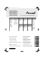
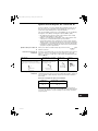
Airwell ST-NK2FL 16R Manuale utente
- Categoria
- Condizionatori d'aria a sistema split
- Tipo
- Manuale utente

Pub. OI-85464189824001
© 2006
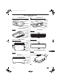
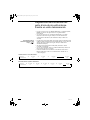
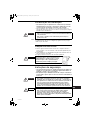
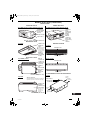
SEMI-CONCEALED CEILING-MOUNTED WALL-MOUNTED
FLAT WALL-MOUNTED
CONCEALED DUCT
(4-WAY)
ST-NKFL 7R
ST-NKFL 9R
ST-NKFL 12R
ST-NKFL 16R
ST-NKFL 18R
ST-NKFL 24R
ST-NKFL 36R
ST-NKFL 48R
ST-NKFL 60R
(2-WAY)
ST-NK2FL 7R
ST-NK2FL 9R
ST-NK2FL 12R
ST-NK2FL 16R
ST-NK2FL 18R
ST-NK2FL 24R
(1-WAY SLIM)
ST-NK1FL 9R
ST-NK1FL 12R
ST-NK1FL 16R
ST-NK1FL 18R
ST-NK1FL 24R
(Mini Semi-Concealed)
AWSI-CAV007-N11
AWSI-CAV009-N11
AWSI-CAV012-N11
AWSI-CAV016-N11
AWSI-CAV018-N11
ST-NPFL 12R
ST-NPFL 16R
ST-NPFL 18R
ST-NPFL 24R
ST-NPFL 36R
ST-NPFL 48R
ST-NWFL 7R
ST-NWFL 9R
ST-NWFL 12R
ST-NWFL 16R
ST-NWFL 18R
ST-NWFL 24R
AWSI-XAV007-N11
AWSI-XAV009-N11
AWSI-XAV012-N11
(Standard Static Pressure)
ST-NDLP 7R
ST-NDLP 9R
ST-NDLP 12R
ST-NDLP 16R
ST-NDLP 18R
ST-NDLP 24R
ST-NDLP 36R
ST-NDLP 48R
(High Static Pressure)
ST-NDHP 24R
ST-NDHP 36R
ST-NDHP 48R
ST-NDHP 76R
ST-NDHP 96R
(Slim Concealed-Duct)
AWSI-DAV007-N11
AWSI-DAV009-N11
AWSI-DAV012-N11
AWSI-DAV016-N11
AWSI-DAV018-N11
FLOOR STANDING
CONCEALED FLOOR
STANDING
HEAT EXCHANGER
WITH DX COIL
ST-NFFL 7R
ST-NFFL 9R
ST-NFFL 12R
ST-NFFL 16R
ST-NFFL 18R
ST-NFFL 24R
ST-NFMFL 7R
ST-NFMFL 9R
ST-NFMFL 12R
ST-NFMFL 16R
ST-NFMFL 18R
ST-NFMFL 24R
AWSI-DEV018-N11
AWSI-DEV024-N11
AWSI-DEV030-N11
Save These Instructions!
Conserver ce mode d’emploi
Bewahren Sie bitte diese
Bedienungsanleitung auf.
Conservate queste istruzioni
Guarde estas instruções
Φυλάξτε τις οδηγίες αυτές
Guarde estas instrucciones
This air conditioner uses the new refrigerant R410A.
Split System Air Conditioner
Climatiseur Split System
Split-System-Klimagerät
Condizionatore d’Aria Split
Aparelho de Ar Condicionado Sistema Split
Κλι ατιστικό Δύο Μονάδων
Acondicionador de Aire de Dos Unidades
• INSTRUCTION MANUAL
• MODE D’EMPLOI
• BEDIENUNGSANLEITUNG
• ISTRUZIONI PER L’USO
• MANUAL DE INSTRUÇÕES
• ΕΓΧΕΙΡΙΔΙΟ ΟΔΗΓΙΩΝ
• MANUAL DE INSTRUCCIONES
OI824001_Airwell-Ecoi_COVER.fm Page 2 Thursday, July 2, 2009 4:03 PM

2
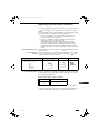
Contents
Page
Product Information........................................................................................... 2
Alert Symbols.................................................................................................... 2
Installation Location .......................................................................................... 3
Electrical Requirements.................................................................................... 3
Safety Instructions............................................................................................. 3
Names of Parts (Indoor Unit) ............................................................................ 4
Wireless Remote Control Unit (Optional parts)................................................. 6
NOTE
Refer to the Instruction Manual attached to the optional Wireless Remote Control Unit
Wired Remote Control Unit (Optional parts) ..................................................... 6
NOTE
Refer to the Instruction Manual attached to the optional Wired Remote Control Unit
Adjusting the Airflow Direction .......................................................................... 7
Adjusting the Airflow Direction for Multiple Indoor Units Using a Single Remote
Control Unit ..................................................................................................... 10
Parts Names and Functions of Direct-Expansion-Coil Outdoor Air Treatment Unit
..... 11
Special Remarks............................................................................................. 12
Care and Cleaning .......................................................................................... 13
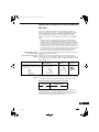
Product Information
If you have problems or questions concerning your Air Conditioner, you will
need the following information. Model and serial numbers are on the nameplate
on the bottom of the cabinet.
Model No. ______________________ Serial No. ____________________
Date of purchase ________________________________________________
Dealer’s address ________________________________________________
Phone number ________________
DECLARATION OF CONFORMITY
This product is marked « » as it satisfies EEC Directive No. 2004/108/EC,
2006/42/EC and 93/68/EEC, and conforms with following standards.
This declaration will become void in case of misusage and/or from non
observance though partial of Manufacturer’s installation and/or operating
instructions.
Note: This air conditioner uses the new refrigerant R410A.
This product is intended for professional use.
Permission from the power supplier is required when installing an outdoor unit
that is connected to a 16 A distribution network.
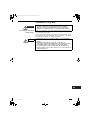
Alert Symbols
The following symbols used in this manual, alert you to potentially
dangerous conditions to users, service personnel or the appliance:
This symbol refers to a hazard or unsafe
practice which can result in severe personal
injury or death.
This symbol refers to a hazard or unsafe
practice which can result in personal injury
or product or property damage.
CAUTION
OI-824-2-GB
01_Airwell_ST-NKFL7R_GB.fm Page 2 Tuesday, July 14, 2009 11:43 AM

3
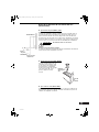
Installation Location
• We recommend that this air conditioner be installed properly by
qualified installation technicians in accordance with the Installation
Instructions provided with the unit.
• Before installation, check that the voltage of the electric supply in your home
or office is the same as the voltage shown on the nameplate.
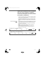
Electrical Requirements
1. All wiring must conform to the local electrical codes. Consult your dealer or a
qualified electrician for details.
2. Each unit must be properly grounded with a ground (or earth) wire or
through the supply wiring.
3. Wiring must be done by a qualified electrician.
Safety Instructions
• Read this Instruction Manual carefully before using this air
conditioner. If you still have any difficulties or problems, consult your
dealer for help.
• This air conditioner is designed to give you comfortable room
conditions. Use this only for its intended purpose as described in this
Instruction Manual.
• Do not install this air conditioner where there are fumes or flammable
gases, or in an extremely humid space such as a greenhouse.
• Do not install the air conditioner where excessively high heat-
generating objects are placed.
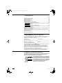
Avoid: To protect the air conditioner from heavy corrosion, avoid installing the
outdoor unit where salty sea water can splash directly onto it or in
sulphurous air near a spa.
To warm up the system, the power mains must
be turned on at least five (5) hours before
operation. Leave the power mains ON unless
you will not be using this appliance for an
extended period.
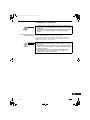
• Never touch the unit with wet hands.
• Never use or store gasoline or other flammable vapor or liquid near
the air conditioner — it is very dangerous.
• This air conditioner has no ventilator for intaking fresh air from
outdoors. You must open doors or windows frequently when you
use gas or oil heating appliances in the same room, which consume
a lot of oxygen from the air. Otherwise there is a risk of suffocation
in an extreme case.
• Do not turn the air conditioner on and off from the power mains
switch. Use the ON/OFF operation button.
• Do not stick anything into the air outlet of the outdoor unit. This is
dangerous because the fan is rotating at high speed.
• Do not let children play with the air conditioner.
• Do not cool or heat the room too much if babies or invalids are present.
CAUTION
Power mains
ON
CAUTION
OI-824-3-GB
01_Airwell_ST-NKFL7R_GB.fm Page 3 Thursday, July 2, 2009 4:01 PM

4
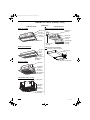
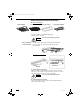
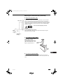
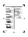
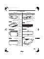
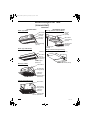
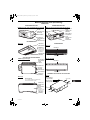
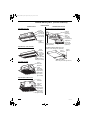
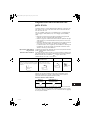
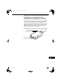
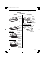
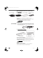
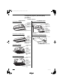
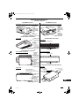
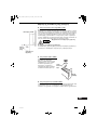
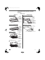
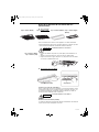
Names of Parts (Indoor Unit)
INDOOR UNIT
SEMI-CONCEALED
NK2FL type (2-WAY)
NK1FL type (1-WAY SLIM)
NKFL type (4-WAY)
Water drain
Water
drain
Air outlet
(2 locations)
Air intake
(2 locations)
Ceiling panel (optional)
Air outlet
Ceiling
panel
(optional)
Air intake grille
(air intake)
CONCEALED DUCT
NDLP type (standard static pressure)
Water drain
Flexible duct
(optional)
Canvas duct
(optional)
Air intake grille
(air intake)
(optional)
Air outlet grille
(optional)
Water drain
Ceiling panel
(optional)
Air outlet
(4 locations)
Air intake grille
(air intake)
CAV type (Mini Semi-Concealed)
Water drain
Ceiling panel
(optional)
Air outlet
(4 locations)
Air intake grille
(air intake)
Water drain
DAV type (Slim Concealed-Duct)
Air intake side filter (rear)
Electrical box
Rectangular solid duct (optional)
OI-824-4-GB
01_Airwell_ST-NKFL7R_GB.fm Page 4 Thursday, July 2, 2009 4:01 PM

5
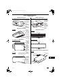
Names of Parts (continued)
INDOOR UNIT
CONCEALED DUCT
Air intake side
duct flange
(rear)
Air outlet side
duct flange
Electrical box
NDHP type (high static pressure) for 24, 36 & 48
CEILING-MOUNTED
NPFL type
NDHP type (high static pressure) for 76 & 96
WALL-MOUNTED
NWFL type
Water drain
Air intake
side duct
flange (rear)
Air outlet
side duct
flange (2
locations)
Electrical
box
NFFL type
Water drain
(You can
connect the
drain pipe
either the right
or left side.)
Air intake
grille (air
intake)
Air outlet (Air
outlet grille)
Air intake
Air outlet
Operation door
(The remote control unit (sold separately) can be
placed inside here.)
Front panel
(A drain pan is
provided inside.)
Air intake
(air filter)
Water drain
CONCEALED DUCT
Air outlet
FLOOR STANDING
NFMFL type (concealed)
Water drain
Drain pan
Front panel
Air outlet
Air outlet duct
connecting
flange
(optional)
Air intake (air
filter)
RA
SA
OA
EA
High-performance
filter
Long-life filter
XAV type (FLAT)
Air intake
Air outlet
HEAT EXCHANGER WITH DX COIL
DEV type
OI-824-5-GB
01_Airwell_ST-NKFL7R_GB.fm Page 5 Thursday, July 2, 2009 4:01 PM

6
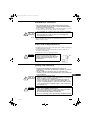
Wireless Remote Control Unit (Optional parts)
Wired Remote Control Unit (Optional parts)
Refer to the Instruction Manual attached to the optional Wireless Remote Control Unit.
Refer to the Instruction Manual attached to the optional Wired Remote Control Unit.
NOTE
NOTE
OI-824-6-GB
01_Airwell_ST-NKFL7R_GB.fm Page 6 Thursday, July 2, 2009 4:01 PM

7
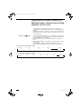
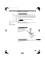
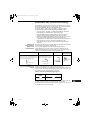
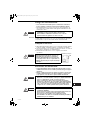
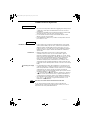
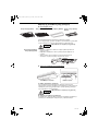
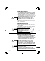
Adjusting the Airflow Direction
The functions differ depending on the indoor unit used. The airflow direction
cannot be set using the remote control unit for any unit which is not listed
below.
4-way type (NKFL), (CAV), 2-way type (NK2FL), 1-way type (NK1FL), ceiling
mounted type (NPFL) and wall mounted type (NWFL), (XAV).
• Never use your hands to move the flap (vertical airflow flap) that is
controlled using the remote control unit.
• When the air conditioner is turned off, the flap (vertical airflow flap)
automatically moves to the downward position.
• The flap (vertical airflow flap) moves to the upward position when
performing the standby operation for heating. The swing operation is
made after the standby operation for heating is released, but swing is
indicated on the remote control unit even during the standby operation for
heating.
Setting the airflow direction The airflow direction changes each time the FLAP button is pressed
during operation.
To activate the swing
operation
Press the FLAP button to set the flap (vertical airflow flap) to the downward
position, and then press the FLAP button again. This displays , and the
airflow automatically swings up and down.
To stop the swing operation Press the FLAP button again during the flap swing operation to stop the flap
at the desired position. Then, the airflow can be set from the top position by
pressing the FLAP button again.
Indicator when swing operation is stopped
During cooling or drying operation, the flap will not stop at the downward
position. Even if the flap is stopped at the downward position during the swing
operation, it will not stop until it moves to the third position from the top.
Heating Cooling and drying Fan operation All operations
Set the flap (vertical airflow flap) to the downward
position. If the flap is set to the upward position,
the warm air may not reach the floor.
The flap (vertical airflow flap) can
be set to one of three positions.
Initial setting
Initial setting
Initial setting
Continuous
operation
Fan and heating Cooling and drying
OI-824-7-GB
01_Airwell_ST-NKFL7R_GB.fm Page 7 Thursday, July 2, 2009 4:01 PM

8
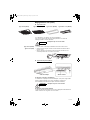
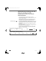
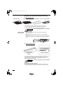
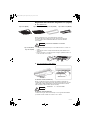
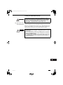
Adjusting the Airflow Direction (continued)
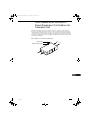
Semi-concealed type
These air conditioners are equipped with auto flaps.
You can set the airflow direction to a specific angle or to the sweep mode
using the remote control unit.
Do not move the flap with your hands.
4-way type (NKFL)
4-way type (CAV)
• The air outlet flap can be easily removed and washed with water.
• Be sure to always stop operation before removing the flap.
• After washing with water, allow it to dry, and then remount it with the arrow
facing outward.
Ceiling mounted type (NPFL)
A. Vertical directions (automatic)
This air conditioner is equipped with an auto flap. You can set the airflow
direction to a specific angle or to the sweep mode using the remote control
unit. (Refer to the description of the remote control unit.)
Do not move the flap with your hands.
B. Horizontal directions (manual)
The horizontal airflow direction can be adjusted manually by moving the
vertical vanes to the left or right.
4-way type (NKFL) 2-way type (NK2FL) 1-way slim type (NK1FL)4-way type (CAV)
CAUTION
Auto flap
Vertical vane
CAUTION
OI-824-8-GB
01_Airwell_ST-NKFL7R_GB.fm Page 8 Thursday, July 2, 2009 4:01 PM

9
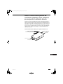
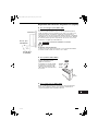
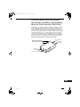
Adjusting the Airflow Direction (continued)
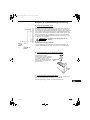
Wall mounted type (NWFL), (XAV)
A. Vertical directions (automatic)
Confirm that the remote control unit has been turned on. Press the FLAP
button to start the flap moving up and down. If you want to stop the flap
movement and to direct the air in the desired direction, press the FLAP button
again. In the cool mode, don’t direct the flap down more than 30°, otherwise,
condensation may drip on to the floor. Zone ‘‘A’’ is the recommended flap
position for cooling.
Do not move the flap with your hands.
B. Horizontal directions (manual)
The horizontal airflow direction can be adjusted manually by moving the
vertical vanes to the left or right.
Floor standing type (NFFL, NFMFL)
It is possible to change the airflow
direction. Remove the air
discharge grille by sliding it to the
right and then lifting it out. Turn the
grille as desired (90, 180, or 270
degrees) and then replace it.
Concealed duct type (NDLP, NDHP)
This air conditioner is not equipped with air outlet parts. These must be
obtained locally. Please refer to the manual of the locally adopted air outlet
parts.
Zone
‘‘A’’ for
cooling
30°
Indoor unit
Zone ‘‘B’’ for
heating
60°
CAUTION
Air discharge
grille
Valve
side
OI-824-9-GB
01_Airwell_ST-NKFL7R_GB.fm Page 9 Thursday, July 2, 2009 4:01 PM

10
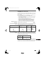
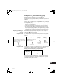
Adjusting the Airflow Direction for
Multiple Indoor Units Using a Single
Remote Control Unit
• The airflow direction cannot be set using the remote control unit for
concealed duct type (NDHP, NDLP, DAV), and floor standing type (NFFL,
NFMFL).
• If multiple indoor units are connected to a remote control unit, the airflow
direction can be set for each indoor unit by selecting the indoor units (see
the operation below).
Auto Flap ( ) button • To set the airflow for individual units, press the UNIT button. Display shows
the indoor unit number under group control. Set the airflow direction for the
indoor unit that is shown on the display.
• Each time UNIT is pressed, the indicator changes in the order shown
below.
• When nothing is displayed, you can make the setting for all indoor units in
one operation.
• The unit number is displayed as Outdoor Unit Number–Indoor Unit
Number. It varies depending on the number of units under group control.
One outdoor unit and eight indoor units
Two outdoor units and four indoor units
No display
Unit No.
1–1
Unit No.
1–2
Unit No.
1–3
Unit No.
1–8
ÎÎ Î
Î
No display
Unit No.
1–1
Unit No.
1–2
Unit No.
1–3
Unit No.
2–4
Î
Unit No.
1–4
Unit No.
2–1
ÎÎÎ Î
Î
OI-824-10-GB
01_Airwell_ST-NKFL7R_GB.fm Page 10 Thursday, July 2, 2009 4:01 PM

11
Parts Names and Functions of
Direct-Expansion-Coil Outdoor Air
Treatment Unit
This unit is designed to remove dirty or stale air from offices, conference rooms and other
indoor spaces and replace it with fresh outdoor air. The unit exchanges heat between the air-
conditioned indoor air and the outside one, and it cools or heats the air using a direct expansion
coil so that it can get fresh air into the room with closely adjusted to the indoor air temperature.
It also provides the appropriate level of humidification during heating operations using a natural
vaporizing-type humidifier.
Direct-expansion-coil outdoor air treatment unit
RA
SA
OA
EA
High-performance filter
Long-life filter
OI-824-11-GB
01_Airwell_ST-NKFL7R_GB.fm Page 11 Thursday, July 2, 2009 4:01 PM

12
Special Remarks
How it works • Once the room temperature reaches the level that was set, the unit
repeats the cycle of turning on and off automatically.
• In order to prevent the humidity in the room from rising again, the indoor
fan also turns off when the unit stops operating.
• The fan speed is set to ‘‘LO.’’ automatically, and cannot be adjusted.
• ‘‘DRY’’ operation is not possible if the outdoor temperature is 15 °C or less.
Heating performance • Because this appliance heats a room by utilizing the heat of the outside air
(heat pump system), the heating efficiency will fall off when the outdoor
temperature is very low. If sufficient heat cannot be obtained with this heat
pump, use another heating appliance in conjunction with this unit.
Defrosting • When the outdoor temperature is low, frost or ice may form on the outdoor
heat exchanger coil, reducing the heating performance. When this
happens, a microcomputer-controlled defrosting system operates. At the
same time, the fan on the indoor unit stops (or runs at very low speed in
some cases) and the ‘‘STANDBY’’ indicator appears on the display until
defrosting is completed. Heating operation then restarts after several
minutes. (This interval will vary slightly depending upon the outdoor
temperature and the way in which frost forms.)
(standby) on the display • For several minutes after the start of heating operation, the indoor fan will
not start running (or it will run at very low speed in some cases) until the
indoor heat exchanger coil has warmed up sufficiently. This is because a
cold draft prevention system is operating. During this period, the ‘‘ ’’
(standby) indicator remains displayed.
• ‘‘ ’’ (standby) remains displayed during defrosting or when the
compressor has been turned off (or when the unit is running at very low
speed) by the thermostat when the system is in the heating mode.
• Upon completion of defrosting and when the compressor is turned on
again, ‘‘ ’’ (standby) will turn off automatically as heating operation
resumes.
Should the power fail while the unit is running
If the power supply for this unit is temporarily cut off, the unit will automatically
resume operation (once the power is restored) using the same settings before
the power was cut off.
‘‘DRY’’ Operation
Heating Operation
NOTE
OI-824-12-GB
01_Airwell_ST-NKFL7R_GB.fm Page 12 Thursday, July 2, 2009 4:01 PM

13
Care and Cleaning
1. For safety, be sure to turn the air conditioner off and also to
disconnect the power before cleaning.
2. Do not pour water on the indoor unit to clean it. This will damage the
internal components and cause an electric shock hazard.
Air intake and outlet side
(Indoor unit)
Clean the air intake and outlet side of the indoor unit with a vacuum cleaner
brush, or wipe them with a clean, soft cloth.
If these parts are stained, use a clean cloth moistened with a mild liquid
detergent. When cleaning the air outlet side, be careful not to force the vanes
out of place.
1. Never use solvents or harsh chemicals when cleaning the indoor
unit. Do not wipe plastic parts using very hot water.
2. Some metal edges and the fins are sharp and may cause injury if
handled improperly; be especially careful when you clean these
parts.
3. The internal coil and other components of the outdoor unit must be
cleaned every year. Consult your dealer or service center.
CAUTION
OI-824-13-GB
01_Airwell_ST-NKFL7R_GB.fm Page 13 Thursday, July 2, 2009 4:01 PM

14
Table des matières
Page
Informations sur le produit .............................................................................. 14
Symboles d’avertissement .............................................................................. 14
Emplacement d’installation ............................................................................. 15
Instructions relatives à l’alimentation .............................................................. 15
Conseils de sécurité........................................................................................ 15
Nom des pièces (unité intérieure) ................................................................... 16
Télécommande sans fil (pièces en option)...................................................... 18
REMARQUE Reportez-vous au Mode d’emploi qui accompagne la télécommande
sans fil en option.
Télécommande avec fil (pièces en option)...................................................... 18
REMARQUE Reportez-vous au Mode d’emploi qui accompagne la télécommande
avec fil en option.
Réglage du flux d’air ....................................................................................... 19
Ajustement de la direction du flux d’air pour plusieurs unités intérieures à l’aide
d’une seule télécommande............................................................................. 22
Nom et fonction des pièces de l’unité de traitement d’air extérieur par serpentin
à détente directe ............................................................................................. 23
Remarques spéciales ..................................................................................... 24
Entretien et nettoyage ..................................................................................... 25
Informations sur le produit
Pour tout problème ou toute question relatifs au climatiseur, il faudra les
informations ci-dessous. Les numéros de série et de modèle figurent sur la
plaque signalétique placée sur le fond du coffret.
No. de modèle ___________________ No. de série. __________________
Date d’achat____________________________________________________
Adresse du concessionnaire _______________________________________
Numéro de téléphone ___________
DÉCLARATION DE CONFORMITÉ
Ce produit est marqué « » puisqu’il est conforme aux Directives CEE No.
2004/108/CE, 2006/42/CE, 93/68/CEE et conforme aux normes suivantes.
Cette déclaration sera nulle en cas d’une utilisation différente de celle déclarée
par le Constructeur et/ou de la non-observation, même si partiale des
instructions d’installation et/ou d’usage.
Remarque : ce climatiseur utilise le nouveau frigorigène R410A.
Ce produit est prévu pour une utilisation professionnelle.
Une autorisation de la compagnie d’électricité est requise lors de l’installation
d’une unité extérieure qui est connectée à un réseau de distribution 16 A.
Symboles d’avertissement
Les symboles suivants utilisés dans ce manuel avertissent d’un danger
potentiel pour l’utilisateur, le personnel d’entretien ou l’appareil :
Ce symbole signale un danger ou des
opérations dangereuses qui risquent d’entraîner
des blessures physiques graves, ou mortelles.
Ce symbole signale un danger ou des
opérations dangereuses qui risquent
d’entraîner des blessures physiques ou des
dommages matériels, notamment de l’appareil.
AVERTISSEMENT
ATTENTION
OI-824-2-FR
02_Airwell_ST-NKFL7R_FR.fm Page 14 Tuesday, July 14, 2009 11:48 AM

15
Emplacement d’installation
• Il est recommandé de faire installer l’appareil par un technicien qualifié
et conformément aux instructions fournies avec l’appareil.
• Avant de procéder à l’installation, vérifier que la tension secteur du local
d’utilisation (bureau ou habitation) est la même que celle indiquée sur la
plaque signalétique.
Instructions relatives à l’alimentation
1. Tous les câbles doivent respecter les codes électriques locaux. Pour les
détails, consulter son concessionnaire ou un électricien qualifié.
2. Chaque élément doit être correctement mis à la terre avec un fil de terre (ou
de masse) ou au moyen d’un câblage d’alimentation.
3. Les raccordements devront être confiés à un électricien qualifié.
Conseils de sécurité
• Lire attentivement ce mode d’emploi avant de faire fonctionner le
climatiseur. Si l’on rencontre des difficultés ou des problèmes,
consulter son concessionnaire.
• Le climatiseur est conçu pour créer un environnement confortable
chez soi. Ne l’utiliser qu’aux fins pour lesquelles il a été prévu, en
suivant les instructions de ce manuel.
• Ne pas installer le climatiseur dans un endroit où existent des
émanations gazeuses ou des gaz inflammables ou dans un endroit
très humide comme une serre.
• Ne pas installer le climatiseur où se trouvent des objets dégageant
une très forte chaleur.
À éviter : Pour protéger le climatiseur de toute corrosion, éviter d’installer l’élément
extérieur dans un endroit qui risque d’être aspergé d’eau de mer ou dans un
environnement sulfureux, par exemple à proximité d’une source thermale.
Pour chauffer le système, il doit être mis sous
tension au moins cinq (5) heures avant son
fonctionnement. Laissez le système sous
tension, sauf si vous n’allez pas l’utiliser
pendant une période de temps importante.
• Ne jamais toucher l’unité avec des mains humides.
• Ne jamais utiliser ni entreposer d’essence ni aucune autre vapeur ou
liquides inflammables près du climatiseur — cela serait extrêmement
dangereux.
• Le climatiseur ne possède pas de ventilateur d’admission d’air frais
extérieur. Il faudra donc ouvrir fréquemment les portes ou les
fenêtres si l’on utilise dans la même pièce des appareils de chauffage
à gaz ou au mazout, qui consomment beaucoup d’oxygène. Sinon, il
y aurait risque d’asphyxie dans les cas extrêmes.
• Ne pas mettre le climatiseur sous et hors tension à l’aide de
l’interrupteur d’alimentation du système. Utiliser le bouton de
marche/arrêt de fonctionnement (ON/OFF).
• Ne rien introduire dans la sortie d’air de l’élément extérieur. Cela est
très dangereux car le ventilateur marche à grande vitesse.
• Ne pas laisser les enfants jouer avec le climatiseur.
• Ne pas trop refroidir ou chauffer une pièce où se trouvent des bébés ou
des malades.
AVERTISSEMENT
ATTENTION
Al
i
mentat
i
on du syst
è
me
ON
AVERTISSEMENT
ATTENTION
OI-824-3-FR
02_Airwell_ST-NKFL7R_FR.fm Page 15 Friday, July 3, 2009 1:07 PM

16
Nom des pièces (unité intérieure)
UNITÉ INTÉRIEURE
CONDUIT SEMI-CACHÉ
Type NK2FL (deux voies)
Type NK1FL (1 voie étroite)
Type NKFL (quatre voies)
Drain
Drain
Sortie d’air
(2 emplacements)
Arrivée d’air
(2 emplacements)
Panneau de
plafond (en
option)
Sortie d’air
Panneau de
plafond (en
option)
Grille de
l’arrivée d’air
(arrivée d’air)
CONDUIT CACHÉ
Type NDLP (pression statique standard)
Drain
Conduit souple
(en option)
Conduit en toile
(en option)
Grille de
l’arrivée d’air
(arrivée d’air)
(en option)
Grille de la sortie
d’air (en option)
Drain
Panneau de
plafond (en
option)
Sortie d’air
(4 emplacements)
Grille de
l’arrivée d’air
(arrivée d’air)
Type CAV (Mini, semi-caché)
Drain
Panneau de
plafond (en
option)
Sortie d’air
(4 emplacements)
Grille de
l’arrivée d’air
(arrivée d’air)
Drain
Type DAV (Mince à conduit caché)
Filtre d’arrivée d’air (arrière)
Coffret électrique
Conduit rigide rectangulaire (en option)
OI-824-4-FR
02_Airwell_ST-NKFL7R_FR.fm Page 16 Friday, July 3, 2009 1:07 PM

17
Nom des pièces (suite)
UNITÉ INTÉRIEURE
CONDUIT CACHÉ
Bride de
conduit
d’arrivée d’air
(arrière)
Bride de conduit
de sortie d’air
Coffret
électrique
T
ype NDHP (pression statique élevée) pour 24, 36 et 48
MONTÉ AU PLAFOND
Type NPFL
Type NDHP (pression statique élevée) pour 76 et 96
MONTÉ AU MUR
Type NWFL
Drain
Bride de
conduit
d’arrivée d’air
(arrière)
Bride de conduit
de sortie d’air
(2 emplacements)
Coffret
électrique
Type NFFL
Drain
(Vous pouvez
connecter le
tuyau de vidange
du côté droit ou
du côté gauche.)
Grille de
l’arrivée d’air
(arrivée d’air)
Sortie d’air
(grille de la
sortie d’air)
Arrivée d’air
Sortie d’air
Porte d’utilisation
(La télécommande (vendue séparément)
peut être placée ici.)
Panneau avant
(Un bac de
récupération est
fourni à
l’intérieur.)
Arrivée d’air
(filtre à air)
Drain
CONDUIT CACHÉ
Sortie d’air
VERTICAL
Type NFMFL (caché)
Drain
Bac de
récupération
Panneau
avant
Sortie d’air
Bride de
connexion au
conduit de
sortie d’air
(en option)
Arrivée d’air
(filtre à air)
Filtre haute
performance
Filtre longue
durée
Type XAV (PLAT)
Arrivée d’air
Sortie d’air
ÉCHANGEUR THERMIQUE À SERPENTIN DX
Type DEV
SA (air fourni)
RA (air de
retour)
OA (air
extérieur)
EA (air
évacué)
OI-824-5-FR
02_Airwell_ST-NKFL7R_FR.fm Page 17 Friday, July 3, 2009 1:07 PM

18
Télécommande sans fil (pièces en
option)
Télécommande avec fil (pièces en
option)
Reportez-vous au Mode d’emploi qui accompagne la télécommande sans fil
en option.
Reportez-vous au Mode d’emploi qui accompagne la télécommande avec fil
en option.
REMARQUE
REMARQUE
OI-824-6-FR
02_Airwell_ST-NKFL7R_FR.fm Page 18 Friday, July 3, 2009 1:07 PM

19
Réglage du flux d’air
Les fonctions varient en fonction de l’unité intérieure utilisée. La direction du
flux d’air ne peut pas être réglée à l’aide de la télécommande pour les unités
listées ci-dessous.
Type 4 voies(NKFL), (CAV), type 2 voies (NK2FL), type 1 voie (NK1FL), type
monté au plafond (NPFL), type monté au mur (NWFL), (XAV).
• Ne jamais déplacer manuellement le volet contrôlé par la télécommande
(volet de circulation d’air vertical).
• Lorsque le climatiseur est mis hors tension, le volet (volet de circulation
d’air vertical) se déplace automatiquement vers le bas.
• Le volet (volet de flux d’air vertical) se déplace vers le haut lorsque le
climatiseur est mis en attente chauffage. Le balancement du volet
commence à la fin d’attente du chauffage, mais le balancement est
indiqué sur la télécommande même pendant l’attente de chauffage.
Réglage de la direction
du flux d’air
La direction du flux d’air change chaque fois que le bouton FLAP
est appuyé pendant le fonctionnement.
Pour activer le balancement
du volet
Appuyez sur le bouton FLAP pour régler le volet (volet de flux d’air vertical)
vers le bas, puis appuyez à nouveau sur le bouton FLAP. Ceci affiche et
le flux d’air balaye de haut en bas et vice versa automatiquement.
Pour arrêter le balancement
du volet
Appuyez sur le bouton FLAP une nouvelle fois pendant le balancement du
volet pour arrêter le volet dans la position souhaitée. Ensuite, le flux d’air peut
être réglé en position supérieure en appuyant à nouveau sur le bouton FLAP.
Voyant lorsque le balancement est arrêté
Pendant le refroidissement et le séchage, le volet ne s’arrête pas orienté vers
le bas. Même si le bouton FLAP est appuyé pendant le balancement du volet,
alors qu’il se trouve orienté vers le bas pendant le balancement, il ne s’arrête
pas jusqu’à ce qu’il se mette dans la troisième position en partant du haut.
Chauffage Refroidissement et
séchage
Utilisation du
ventilateur
Toutes
opérations
Réglez le volet (volet de flux d’air vertical) vers le
bas. Si le volet est réglé en position haute, l’air
chaud risque de ne pas atteindre le sol.
Le volet (volet de flux d’air vertical)
peut être réglé sur trois positions
différentes.
Réglage initial
Réglage initial
Réglage initial
Fonctionnement
continu
Ventilation et
chauffage
Refroidissement et séchage
OI-824-7-FR
02_Airwell_ST-NKFL7R_FR.fm Page 19 Friday, July 3, 2009 1:07 PM

20
Réglage du flux d’air (suite)
Type semi-caché
Ces climatiseurs sont équipés de volets automatiques.
Vous pouvez régler le flux d’air à un angle particulier ou en mode de
balayage à l’aide de la télécommande.
Ne déplacez pas le volet à la main.
Type 4 voies (NKFL)
Type 4 voies (CAV)
• Le volet de la sortie d’air peut facilement être retiré et lavé à l’eau.
• Assurez-vous de toujours arrêter le fonctionnement de l’unité avant de
retirer le volet.
• Après le lavage à l’eau, laissez sécher et remontez à l’unité en vous
assurant que la flèche est orientée vers le haut.
Type monté au plafond (NPFL)
A. Directions verticales (automatique)
Ce climatiseur est équipé d’un volet automatique. Vous pouvez régler le flux
d’air à un angle particulier ou en mode de balayage à l’aide de la
télécommande. (Consultez la description de la télécommande.)
Ne déplacez pas le volet à la main.
B. Directions horizontales (manuel)
La direction de flux horizontal de l’air se règle en déplaçant manuellement les
ailettes verticales vers la gauche ou vers la droite.
Type 4 voies (NKFL) Type 2 voies (NK2FL) Type mince 1 voie (NK1FL)Type 4 voies (CAV)
ATTENTION
Volet automatique
Ailette verticale
ATTENTION
OI-824-8-FR
02_Airwell_ST-NKFL7R_FR.fm Page 20 Friday, July 3, 2009 1:07 PM
La pagina si sta caricando...
La pagina si sta caricando...
La pagina si sta caricando...
La pagina si sta caricando...
La pagina si sta caricando...
La pagina si sta caricando...
La pagina si sta caricando...
La pagina si sta caricando...
La pagina si sta caricando...
La pagina si sta caricando...
La pagina si sta caricando...
La pagina si sta caricando...
La pagina si sta caricando...
La pagina si sta caricando...
La pagina si sta caricando...
La pagina si sta caricando...
La pagina si sta caricando...
La pagina si sta caricando...
La pagina si sta caricando...
La pagina si sta caricando...
La pagina si sta caricando...
La pagina si sta caricando...
La pagina si sta caricando...
La pagina si sta caricando...
La pagina si sta caricando...
La pagina si sta caricando...
La pagina si sta caricando...
La pagina si sta caricando...
La pagina si sta caricando...
La pagina si sta caricando...
La pagina si sta caricando...
La pagina si sta caricando...
La pagina si sta caricando...
La pagina si sta caricando...
La pagina si sta caricando...
La pagina si sta caricando...
La pagina si sta caricando...
La pagina si sta caricando...
La pagina si sta caricando...
La pagina si sta caricando...
La pagina si sta caricando...
La pagina si sta caricando...
La pagina si sta caricando...
La pagina si sta caricando...
La pagina si sta caricando...
La pagina si sta caricando...
La pagina si sta caricando...
La pagina si sta caricando...
La pagina si sta caricando...
La pagina si sta caricando...
La pagina si sta caricando...
La pagina si sta caricando...
La pagina si sta caricando...
La pagina si sta caricando...
La pagina si sta caricando...
La pagina si sta caricando...
La pagina si sta caricando...
La pagina si sta caricando...
La pagina si sta caricando...
La pagina si sta caricando...
La pagina si sta caricando...
La pagina si sta caricando...
La pagina si sta caricando...
La pagina si sta caricando...
La pagina si sta caricando...
La pagina si sta caricando...
La pagina si sta caricando...
La pagina si sta caricando...
-
 1
1
-
 2
2
-
 3
3
-
 4
4
-
 5
5
-
 6
6
-
 7
7
-
 8
8
-
 9
9
-
 10
10
-
 11
11
-
 12
12
-
 13
13
-
 14
14
-
 15
15
-
 16
16
-
 17
17
-
 18
18
-
 19
19
-
 20
20
-
 21
21
-
 22
22
-
 23
23
-
 24
24
-
 25
25
-
 26
26
-
 27
27
-
 28
28
-
 29
29
-
 30
30
-
 31
31
-
 32
32
-
 33
33
-
 34
34
-
 35
35
-
 36
36
-
 37
37
-
 38
38
-
 39
39
-
 40
40
-
 41
41
-
 42
42
-
 43
43
-
 44
44
-
 45
45
-
 46
46
-
 47
47
-
 48
48
-
 49
49
-
 50
50
-
 51
51
-
 52
52
-
 53
53
-
 54
54
-
 55
55
-
 56
56
-
 57
57
-
 58
58
-
 59
59
-
 60
60
-
 61
61
-
 62
62
-
 63
63
-
 64
64
-
 65
65
-
 66
66
-
 67
67
-
 68
68
-
 69
69
-
 70
70
-
 71
71
-
 72
72
-
 73
73
-
 74
74
-
 75
75
-
 76
76
-
 77
77
-
 78
78
-
 79
79
-
 80
80
-
 81
81
-
 82
82
-
 83
83
-
 84
84
-
 85
85
-
 86
86
-
 87
87
-
 88
88


Airwell ST-NK2FL 16R Manuale utente
- Categoria
- Condizionatori d'aria a sistema split
- Tipo
- Manuale utente
in altre lingue
- English: Airwell ST-NK2FL 16R User manual
- français: Airwell ST-NK2FL 16R Manuel utilisateur
- español: Airwell ST-NK2FL 16R Manual de usuario
- Deutsch: Airwell ST-NK2FL 16R Benutzerhandbuch
- português: Airwell ST-NK2FL 16R Manual do usuário
Altri documenti
-
Panasonic U14ME1E81 Istruzioni per l'uso
-
Panasonic S200PE1E8A Manuale del proprietario
-
-
Panasonic S-45MT1E5 Manuale del proprietario
-
Panasonic U71PEY1E5 Manuale del proprietario
-
-
-
Smartwares DIC-211 Manuale utente
-
Panasonic S36MY2E5 Manuale del proprietario
-
Panasonic S28MK2E5A Istruzioni per l'uso