
CV623322089585464609230020
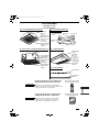
Operating Instructions
Air Conditioner
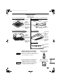
* Shows U1 type (4-Way Cassette)
ENGLISH
FRANÇAIS
ESPAÑOL
DEUTSCH
ITALIANO
NEDERLANDS
PORTUGUÊS
EΛΛΗΝΙΚΆ
БЪЛГАРСКИ
РУССКИЙ
УКРАЇНСЬКА
2 ~ 13
14 ~ 25
26 ~ 37
38 ~ 49
50 ~ 61
62 ~ 73
74 ~ 85
86 ~ 97
98 ~ 109
110 ~ 121
122 ~ 134
Before operating the unit, read these operating instructions thoroughly and keep them for future reference.
Avant d’utiliser l’appareil, lisez ce mode d’emploi dans son intégralité et conservez-le pour toute référence ultérieure.
Bevor Sie das Gerät in Betrieb nehmen, lesen Sie bitte diese Bedienungsanleitung aufmerksam
durch und bewahren Sie sie für die künftige Verwendung auf.
Prima di utilizzare l’unità, leggere a fondo queste istruzioni per l’uso e conservarle come riferimento futuro.
Преди да започнете експлоатация на този уред, прочетете внимателно тези инструкции и ги
запазете, за да можете да правите справки с тях и в бъдеще.
Lees deze gebruiksinstructies goed door voor u het apparaat gebruikt en bewaar ze voor toekomstig gebruik.
Antes de utilizar o aparelho, leia completamente este manual de instruções e guarde-o para futuras referências.
Перед использованием этого устройства внимательно прочитайте настоящую инструкцию по
эксплуатации и сохраните ее для дальнейших справок.
Уважно прочитайте цю інструкцію з експлуатації перед тим, як увімкнути пристрій, та
збережіть її на майбутнє.
Πριν θέσετε τη μονάδα σε λειτουργία, διαβάστε πολύ καλά αυτές τις οδηγίες χρήσης και
διατηρήστε τις για μελλοντική αναφορά.
Antes de operar la unidad, lea atentamente estas instrucciones de funcionamiento y guárdelas para futuras consultas.
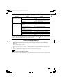
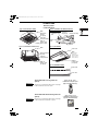
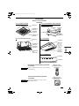
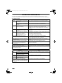
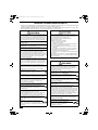
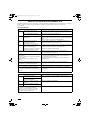
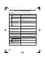
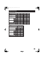
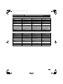
Indoor Units
4-Way
Cassette
60x60 (Y1 type)
S-36PY1E5
S-50PY1E5
Model No.
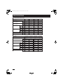
Indoor Units
4-Way
Cassette
(U1 type)
S-36PU1E5
S-50PU1E5
S-60PU1E5
S-71PU1E5
Indoor Units
Ceiling
(T1 type)
S-36PT1E5
S-50PT1E5
S-60PT1E5
S-71PT1E5
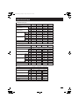
Indoor Units
Wall
Mounted
(K1 type)
S-36PK1E5
S-50PK1E5
S-60PK1E5
S-71PK1E5
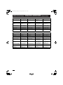
Outdoor Units
Single Split
(Single-
phase)
U-50PE1E5
U-60PEY1E5
U-71PEY1E5
Indoor Units
Ducted
(N1 type)
S-36PN1E5
S-50PN1E5
S-60PN1E5
S-71PN1E5
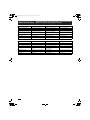
Indoor Units
Low Silhouette
Ducted
(F1 type)
S-36PF1E5
S-50PF1E5
S-60PF1E5
S-71PF1E5
Panasonic Corporation
1006 Kadoma, Kadoma City, Osaka, Japan

2
CONTENTS
Page
PRODUCT INFORMATION...........................................................................................................2
SAFETY PRECAUTIONS..............................................................................................................2
INSTALLATION LOCATION...........................................................................................................3
ELECTRICAL REQUIREMENTS ..................................................................................................3
SAFETY INSTRUCTIONS.............................................................................................................4
INFORMATION..............................................................................................................................6
OPERATION..................................................................................................................................7
ADJUSTING AIRFLOW DIRECTION............................................................................................8
ADJUSTING AIRFLOW DIRECTION FOR MULTIPLE INDOOR UNITS USING SINGLE
REMOTE CONTROLLER (WIRED) ............................................................................................10
SPECIAL REMARKS ..................................................................................................................11
CARE AND CLEANING ..............................................................................................................11
TROUBLESHOOTING ................................................................................................................12
CHECK BEFORE REQUIRING SERVICES................................................................................13
TIPS FOR ENERGY SAVING .....................................................................................................13
SPECIFICATIONS.....................................................................................................................135
PRODUCT INFORMATION
If you have problems or questions concerning your Air Conditioner, you will need the following
information. Model and serial numbers are on the nameplate on the bottom of the cabinet.
Model No. _________________________________ Serial No. _______________________
Date of purchase ______________________________________________________________
Dealer’s address ______________________________________________________________
Phone number________________________________________________________________
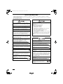
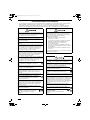
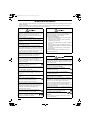
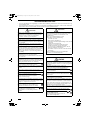
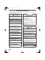
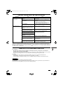
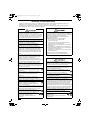
SAFETY PRECAUTIONS
The following symbols used in this manual, alert you to potentially dangerous conditions
to users, service personnel or the appliance:
This symbol refers to a hazard or unsafe practice
which can result in severe personal injury or
death.
This symbol refers to a hazard or unsafe practice
which can result in personal injury or product or
property damage.
01_85464609230020_EN.fm Page 2 Thursday, December 27, 2012 4:22 PM

3
INSTALLATION LOCATION
• We recommend that this air conditioner be installed properly by qualified installation
technicians in accordance with the Installation Instructions provided with the unit.
• Before installation, check that the voltage of the electric supply in your home or office is the
same as the voltage shown on the nameplate.
ELECTRICAL REQUIREMENTS
1. All wiring must conform to the local electrical codes. Consult your dealer or a qualified
electrician for details.
2. Each unit must be properly grounded with a ground (or earth) wire or through the supply
wiring.
3. Wiring must be done by a qualified electrician.
• Do not install this air conditioner where there are fumes or flammable gases, or in an
extremely humid space such as a greenhouse.
• Do not install the air conditioner where excessively high heat-generating objects
are placed.
Avoid: To protect the air conditioner from heavy corrosion, avoid installing the outdoor unit where
salty sea water can splash directly onto it or in sulphurous air near a spa.
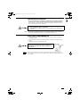
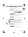
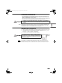
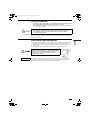
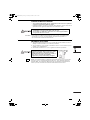
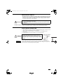
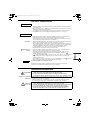
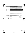
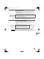
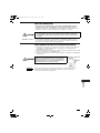
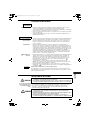
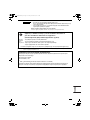
To warm up the system, the power mains must be turned on
at least five (5) hours before operation. Leave the power
mains ON unless you will not be using this appliance for an
extended period.
Pull off the power plug from a receptacle, or switch off the breaker, or switch off the power
disconnecting mean to isolate the air conditioner from the main power supply when not in use
for a long time.
Power mains
ON
NOTE
01_85464609230020_EN.fm Page 3 Thursday, December 27, 2012 4:22 PM

4
SAFETY INSTRUCTIONS
• Read these Operating Instructions carefully before using this air conditioner. If you still have any difficulties or problems,
consult your dealer for help.
• This air conditioner is designed to give you comfortable room conditions. Use this only for its intended purpose as described in
these Operating Instructions.
Confirm to authorized dealer or specialist on usage of
specified refrigerant type. Using of refrigerant other than
the specified type may cause product damage, burst and
injury etc.
Never touch the unit with wet hands.
Never use or store gasoline or other flammable vapor or
liquid near the air conditioner — it is very dangerous.
Do not use this appliance in a potentially explosive
atmosphere.
This air conditioner has no ventilator for intaking fresh air
from outdoors. You must open doors or windows frequently
when you use gas or oil heating appliances in the same
room, which consume a lot of oxygen from the air.
Otherwise there is a risk of suffocation in an extreme case.
Provide a power outlet to be used exclusively for each unit,
and a power supply disconnect, circuit breaker and earth
leakage breaker for overcurrent protection should be
provided in the exclusive line.
Provide a power outlet exclusively for each unit, and full
disconnection means having a contact separation in all
poles must be incorporated in the fixed wiring in
accordance with the wiring rules.
To prevent possible hazards from insulation failure,
the unit must be grounded.
Do not clean inside the indoor and outdoor units by users.
Engage authorized dealer or specialist for cleaning.
In case of malfunction of this appliance, do not repair by
yourself. Contact to the sales dealer or service dealer for a
repair.
Refrigerant gas leakage may cause fire.
For safety, be sure to turn the air conditioner off and
also to disconnect the power before cleaning or
servicing.
Pull off the power plug from a receptacle, or switch off the
breaker, or switch off the power disconnecting mean to
isolate the air conditioner from the main power supply in
case of emergency.
Do not insert your fingers or other objects into the air
conditioner indoor or outdoor unit, rotating parts may
cause injury.
Do not use modified cord, joint cord, extension
cord or unspecified cord to prevent overheating
and fire.
Stop using the product when any abnormality/failure occurs
and disconnect the power plug or turn off the power switch
and breaker.
(Risk of smoke/fire/electric shock)
Examples of abnormality/failure
• The ELCB trips frequently.
• Burning smell is observed.
• Abnormal noise or vibration of the unit is observed.
• Water leaks from the indoor unit.
• Power cord or plug becomes abnormally hot.
• Fan speed cannot be controlled.
• The unit stops running immediately even if it is switched
on for operation.
• The fan does not stop even if the operation is stopped.
Contact immediately your local dealer for maintenance/
repair.
This appliance is intended to be used by expert or trained
users in shops, in light industry and on farms, or for
commercial use by lay persons.
Do not turn the air conditioner on and off from the power
mains switch. Use the ON/OFF operation button.
Do not stick anything into the air outlet of the outdoor
unit. This is dangerous because the fan is rotating at
high speed.
Do not touch the air inlet or the sharp aluminum fins
of the outdoor unit. You may get injured.
Keep the fire alarm and the air outlet at least 1.5m away
from the unit.
This appliance is not intended for use by persons(including
children) with reduced physical, sensory or mental
capabilities, or lack of experience and knowledge, unless
they have been given supervision or instruction concerning
use of the appliance by a person responsible for their
safety. Children should be supervised to ensure that do not
play with the appliance.
Do not cool or heat the room too much if babies or invalids
are present.
Do not sit or step on the unit. You may fall down
accidentally.
Do not stick any object into the FAN CASE.
You may be injured and the unit may be
damaged.
01_85464609230020_EN.fm Page 4 Thursday, December 27, 2012 4:22 PM

5
• The compressor may occasionally stop during thunderstorms.
This is not a mechanical failure. The unit automatically recovers after a few minutes.
• The English text is the original instructions. Other languages are translation of the
original instructions.
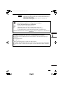
Stop using the product when any abnormality/failure occurs and
disconnect the power plug.
(Risk of smoke/fire/electric shock)
Examples of
abnormality/
failure
- The product sometimes does not start when turned on.
- The power is sometimes disconnected when the cord is moved.
- Burnt odor or abnormal noise is detected during operation.
- The body is deformed or abnormally hot.
Contact immediately your local dealer for maintenance/repair.
IMPORTANT INFORMATION REGARDING THE REFRIGERANT USED
This product contains fluorinated greenhouse gases covered by the Kyoto Protocol. Do not vent gases into the
atmosphere.
Refrigerant type: R410A
GWP
(1)
value: 1975
(1)
GWP = global warming potential
Periodical inspections for refrigerant leaks may be required depending on European or local legislation.
Please contact your local dealer for more information.
NOTICE
01_85464609230020_EN.fm Page 5 Thursday, December 27, 2012 4:22 PM

6
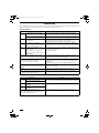
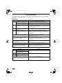
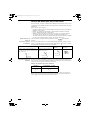
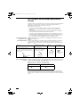
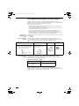
INFORMATION
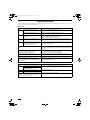
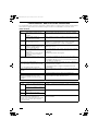
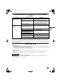
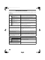
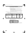
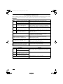
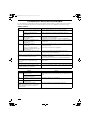
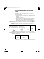
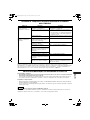
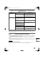
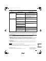
Operation Condition
Use this air conditioner under the following temperature range.
Indoor temperature range:
Cooling mode 14°C ~ 25°C (*WBT) / 18°C ~ 32°C (*DBT)
Heating mode 16°C ~ 30°C (*DBT)
Outdoor temperature range:
Cooling mode -15°C ~ 46°C (*DBT)
*1 -10°C ~ 43°C (*DBT)
Heating mode -20°C ~ 18°C (*WBT) / -20°C ~ 24°C (*DBT)
*1 -15°C ~ 18°C (*WBT) / -15°C ~ 24°C (*DBT)
* DBT: Dry bulb temperature
* WBT: Wet bulb temperature
* 1 When connecting U-60PEY1E5, U-71PEY1E5
Information for Users on Collection and Disposal of Old Equipment and Used Batteries
These symbols on the products, packaging, and/or accompanying documents mean that used electrical and
electronic products and batteries should not be mixed with general household waste.
For proper treatment, recovery and recycling of old products and used batteries, please take them to
applicable collection points, in accordance with your national legislation and the Directives 2002/96/EC and
2006/66/EC.
By disposing of these products and batteries correctly, you will help to save valuable resources and prevent
any potential negative effects on human health and the environment which could otherwise arise from
inappropriate waste handling.
For more information about collection and recycling of old products and batteries, please contact your local
municipality, your waste disposal service or the point of sale where you purchased the items.
Penalties may be applicable for incorrect disposal of this waste, in accordance with national legislation.
For business users in the European Union
If you wish to discard electrical and electronic equipment, please contact your dealer or supplier for further
information.
[Information on Disposal in other Countries outside the European Union]
These symbols are only valid in the European Union. If you wish to discard these items, please contact your
local authorities or dealer and ask for the correct method of disposal.
Note for the battery symbol (bottom two symbol examples):
This symbol might be used in combination with a chemical symbol. In this case it complies with the requirement
set by the Directive for the chemical involved.
Pb
01_85464609230020_EN.fm Page 6 Thursday, December 27, 2012 4:22 PM

7
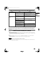
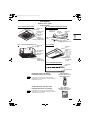
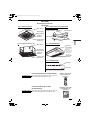
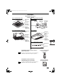
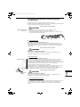
OPERATION
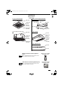
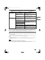
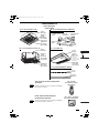
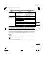
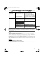
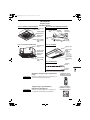
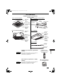
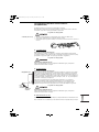
Names of Parts
INDOOR UNIT
Wireless Remote Controller (Optional
parts)
Refer to the Operating Instructions attached to the
optional Wireless Remote Controller.
Timer Remote Controller (Optional parts)
Refer to the Operating Instructions attached to the
optional Timer Remote Controller.
Water drain
Ceiling panel
(optional)
Air outlet
(4 locations)
Air intake grille
(air intake)
Suspension
bolt
Ceiling material
Bolt anchor
Air outlet duct
Indoor unit
Air-outlet grille
U1 Type (4-WAY CASSETTE) F1 Type (LOW SILHOUETTE DUCTED)
N1 Type (DUCTED)
Y1 type (4-Way Cassette 60×60)
Water drain
Ceiling panel
(optional)
Air outlet
(4 locations)
Air intake grille
(air intake)
Water drain
(You can
connect the
drain pipe
either the right
or left side.)
Air intake
grille
(air intake)
Air outlet
T1 type (Ceiling)
Air intake
Air outlet
K1 type (Wall Mounted)
(Wireless type: available
for all indoor units)
NOTE
(Wired type: available
for all indoor units)
NOTE
01_85464609230020_EN.fm Page 7 Thursday, December 27, 2012 4:22 PM

8
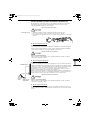
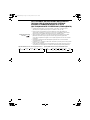
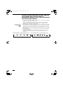
ADJUSTING AIRFLOW DIRECTION
The functions differ depending on the indoor unit used. The airflow direction cannot be set
using the remote controller for any unit which is not listed below.
U1 type, Y1 type, T1 type and K1 type.
• Never use your hands to move the flap (vertical airflow flap) that is controlled using the
remote controller.
• When the air conditioner is turned off, the flap (vertical airflow flap) automatically moves to
the downward position.
• The flap (vertical airflow flap) moves to the upward position when performing the standby
operation for heating. The swing operation is made after the standby operation for heating is
released, but swing is indicated on the remote controller even during the standby operation
for heating.
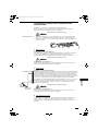
Setting the airflow
direction
The airflow direction changes each time the FLAP button is pressed during operation.
To activate the swing
operation
Press the FLAP button to set the flap (vertical airflow flap) to the downward position, and then
press the FLAP button again. This displays , and the airflow automatically swings up and
down.
To stop the swing
operation
Press the FLAP button again during the flap swing operation to stop the flap at the desired
position. Then, the airflow can be set from the top position by pressing the FLAP button again.
Indicator when swing operation is stopped
During cooling or drying operation, the flap will not stop at the downward position. Even if the
flap is stopped at the downward position during the swing operation, it will not stop until it
moves to the third position from the top.
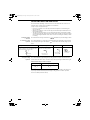
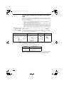
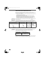
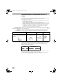
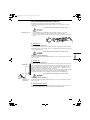
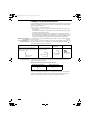
Heating Cooling and drying Fan operation All operations
Set the flap (vertical airflow flap) to the downward
position. If the flap is set to the upward position,
the warm air may not reach the floor.
The flap (vertical airflow flap) can
be set to one of three positions.
Initial setting
Initial setting
Initial setting
Continuous
operation
Fan and heating Cooling and drying
01_85464609230020_EN.fm Page 8 Thursday, December 27, 2012 4:22 PM

9
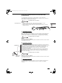
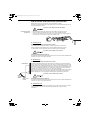
ADJUSTING AIRFLOW DIRECTION (CONTINUED)
U1 type air conditioner is equipped with auto flaps.
You can set the airflow direction to a specific angle or to the sweep mode using the remote
controller.
Do not move the flap with your hands.
4-way (U1, Y1 type) • The air outlet flap can be easily removed and washed with water.
• Be sure to always stop operation before removing the flap.
• After washing with water, allow it to dry, and then remount it with the arrow facing outward.
Ceiling mounted type (T1)
Vertical directions (automatic)
This air conditioner is equipped with an auto flap. You can set the airflow direction to a specific
angle or to the sweep mode using the remote controller. (Refer to the description of the remote
controller.)
Do not move the flap with your hands.
Horizontal directions (manual)
The horizontal airflow direction can be adjusted manually by moving the vertical vanes to the
left or right.
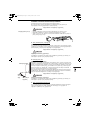
Wall mounted type (K1)
Vertical directions (automatic)
Confirm that the remote controller has been turned on. Press the FLAP button to start the flap
moving up and down. If you want to stop the flap movement and to direct the air in the desired
direction, press the FLAP button again. In the cool mode, do not direct the flap down and move
out of the cooling zone “A”, otherwise, condensation may drip on to the floor. Zone ‘‘A’’ is the
recommended flap position for cooling.
When operating continuously in the fixed airflow direction setting for about an hour, the airflow
direction is automatically controlled and the flap position is changed. The airflow direction may
be different from the display on the remote controller.
Do not move the flap with your hands.
Horizontal directions (manual)
The horizontal airflow direction can be adjusted manually by moving the vertical vanes to the
left or right.
Concealed duct type (F1, N1)
This air conditioner is not equipped with air outlet parts. These must be obtained locally. Please
refer to the manual of the locally adopted air outlet parts.
Indoor unit
Zone ‘‘B’’ for
heating
Zone
‘‘A’’ for
cooling
01_85464609230020_EN.fm Page 9 Thursday, December 27, 2012 4:22 PM

10
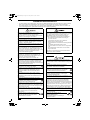
ADJUSTING AIRFLOW DIRECTION FOR MULTIPLE
INDOOR UNITS USING SINGLE REMOTE
CONTROLLER (WIRED)
• The airflow direction cannot be set using the remote controller for the concealed duct type
(F1, N1).
• If multiple indoor units are connected to a remote controller, the airflow direction can be set
for each indoor unit by selecting the indoor units (see the operation below).
Auto Flap ( ) button
• To set the airflow for individual units, press the UNIT button. Display shows the indoor unit
number under group control. Set the airflow direction for the indoor unit that is shown on the
display.
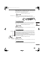
• Each time UNIT is pressed, the indicator changes in the order shown below.
• When nothing is displayed, you can make the setting for all indoor units in one operation.
• The unit number is displayed as Outdoor Unit Number–Indoor Unit Number. It varies
depending on the number of units under group control.
One outdoor unit and eight indoor units Two outdoor units and four indoor units
No display
Unit No.
1–1
Unit No.
1–2
Unit No.
1–3
Unit No.
1–8
No
display
Unit
No.
1–1
Unit
No.
1–2
Unit
No.
1–3
Unit
No.
2–4
Unit
No.
1–4
Unit
No.
2–1
01_85464609230020_EN.fm Page 10 Thursday, December 27, 2012 4:22 PM

11
SPECIAL REMARKS
CARE AND CLEANING
How it works • Once the room temperature reaches the level that was set, the unit repeats the cycle of
turning on and off automatically.
• In order to prevent the humidity in the room from rising again, the indoor fan also turns off
when the unit stops operating.
• The fan speed is set to ‘‘LO.’’ automatically, and cannot be adjusted.
• ‘‘DRY’’ operation is not possible if the outdoor temperature is 15 °C or less.
Heating performance • Because this appliance heats a room by utilizing the heat of the outside air (heat pump
system), the heating efficiency will fall off when the outdoor temperature is very low. If
sufficient heat cannot be obtained with this heat pump, use another heating appliance in
conjunction with this unit.
Defrosting • When the outdoor temperature is low, frost or ice may form on the outdoor heat exchanger
coil, reducing the heating performance. When this happens, a microcomputer-controlled
defrosting system operates. At the same time, the fan on the indoor unit stops (or runs at
very low speed in some cases) and the ‘‘STANDBY’’ indicator appears on the display until
defrosting is completed. Heating operation then restarts after several minutes. (This interval
will vary slightly depending upon the outdoor temperature and the way in which frost forms.)
(standby) on the
display
• For several minutes after the start of heating operation, the indoor fan will not start running
(or it will run at very low speed in some cases) until the indoor heat exchanger coil has
warmed up sufficiently. This is because a cold draft prevention system is operating. During
this period, the ‘‘ ’’ (standby) indicator remains displayed.
• ‘‘ ’’ (standby) remains displayed during defrosting or when the compressor has been
turned off (or when the unit is running at very low speed) by the thermostat when the
system is in the heating mode.
• Upon completion of defrosting and when the compressor is turned on again, ‘‘ ’’
(standby) will turn off automatically as heating operation resumes.
Should the power fail while the unit is running
If the power supply for this unit is temporarily cut off, the unit will automatically resume
operation (once the power is restored) using the same settings before the power was cut off.
1. For safety, be sure to turn the air conditioner off and also to disconnect the power
before cleaning.
2. Do not pour water on the indoor unit to clean it. This will damage the internal
components and cause an electric shock hazard.
Air intake and outlet side
(Indoor unit)
Clean the air intake and outlet side of the indoor unit with a vacuum cleaner brush, or wipe
them with a clean, soft cloth.
If these parts are stained, use a clean cloth moistened with water. When cleaning the air outlet
side, be careful not to force the vanes out of place.
1. Never use solvents or harsh chemicals when cleaning the indoor unit. Do not wipe
plastic parts using very hot water.
2. Some metal edges and the fins are sharp and may cause injury if handled
improperly; be especially careful when you clean these parts.
3. The internal coil and other components of the outdoor unit must be cleaned
periodically. Consult your dealer or service center.
‘‘DRY’’ Operation
Heating Operation
NOTE
01_85464609230020_EN.fm Page 11 Thursday, December 27, 2012 4:22 PM

12
TROUBLESHOOTING
If your air conditioner does not work properly, first check the following points before requesting service. If it still does not work
properly, contact your dealer or a service center.
INDOOR UNIT
OUTDOOR UNIT
Symptom Cause
Noise Sound like streaming water during
operation or after operation
• Sound of refrigerant liquid flowing inside unit
• Sound of drainage water through drain pipe
Cracking noise during operation or
when operation stops.
Cracking sound due to temperature changes of parts
Odor Discharged air is smelled during
operation.
Indoor odor components, cigarette odor and cosmetic odor accumurated
in the air conditioner and its air is discharged.
Unit inside is dusty. Consult your dealer.
Dewdrop Dewdrop gets accumurated near air
discharge during operation
Indoor moisture is cooled by cool wind and accumulated by dewdrop.
Fog Fog occurs during operation in cooling
mode.
(Places where large amounts of oil
mist exist at restaurants.)
• Cleaning is necessary because unit inside (heat exchanger) is dirty.
Consult your dealer as technical engineering is required.
• During defrost operation
Fan is rotating for a while even though operation
stops.
• Fan rotating makes operation smoothly.
• Fan may sometimes rotates because of drying heat exchanger due to
settings.
Wind-direction changes while operating.
Wind-direction setting cannot be made.
Wind-direction cannot be changed.
• When air discharge temperature is low or during defrost operation,
horizontal wind flow is made automatically.
• Flap position is occasionally set up individually.
When wind-direction is changed, flap operates
several times and stops at designated position.
When wind-direction is changed, flap operates after searching for
standard position.
Dust Dust accumulation inside indoor unit is discharged.
At the initial high-speed operation, the fan may
sometimes rotate faster (for 3 to 30 minutes) than
the setting speed.
This is for operation check in order to confirm whether the fan motor
rotation is within use range.
Symptom Cause
No
operation
When power is turned ON instantly. Operation is not activated for the first approx. 3 minutes because
compressor protection circuit is activated.
When operation is stopped and
resumed immediately.
Noise Noise often occurs in heating mode. During defrost operation
Steam Steam often occurs in heating mode.
When stopped by remote controller, outdoor unit fan
is sometimes operating for a while even though
outdoor compressor is stopped.
Fan rotating makes operation smoothly.
01_85464609230020_EN.fm Page 12 Thursday, December 27, 2012 4:22 PM

13
CHECK BEFORE REQUIRING SERVICES
If your air conditioner still does not work properly although you checked the points as described above, first stop the operation and
turn off the power switch. Then contact your dealer and report the serial number and symptom. Never repair your air conditioner
by yourself since it is very dangerous for you to do so. You also report if the inspection mark and the letters E, F, H, L, P in
combination with the numbers appear on the LCD of the remote control unit.
TIPS FOR ENERGY SAVING
Avoid
• Do not block the air intake and outlet of the unit. If either is obstructed, the unit will not work well, and may be
damaged.
• Do not let direct sunlight into the room. Use sunshades, blinds or curtains. If the walls and ceiling of the room are warmed by
the sun, it will take longer to cool the room.
Do
• Always try to keep the air filter clean. (Refer to “CARE AND CLEANING”.) A clogged filter will impair the performance of the
unit.
• To prevent conditioned air from escaping, keep windows, doors and any other openings closed.
Should the power fail while the unit is running
If the power supply for this unit is temporarily cut off, the unit will automatically resume operation once power is restored using the
same settings before the power was interrupted.
Symptom Cause Remedy
Air conditioner does not run at
all although power is turned
on.
Power failure or after power failure Press ON/OFF operation button on remote control
unit again.
Operation button is turned off. • Switch on power if breaker is turned off.
• If breaker has been tripped, consult your dealer
without turning it on.
Fuse blow out. If blown out, consult your dealer.
Poor cooling or heating
performance
Air intake or air discharge port of indoor
and outdoor units is clogged with dust or
obstacles.
Remove dust or obstruction.
Wind speed switch is set to “Low”. Change to “High” or “Strong”.
Improper temperature settings Refer to “TIPS FOR ENERGY SAVING”.
Room is exposed to direct sunlight in
cooling mode.
Doors and /or windows are open.
Air filter is clogged. Refer to “CARE AND CLEANING”.
Too much heat sources in room in
cooling mode.
Use minimum heat sources and in a short time.
Too many people in room in cooling
mode.
Reduce temperature settings or change to “High” or
“Strong”.
NOTE
01_85464609230020_EN.fm Page 13 Thursday, December 27, 2012 4:22 PM

14
TABLE DES MATIÈRES
Page
INFORMATIONS SUR LE PRODUIT..........................................................................................14
PRÉCAUTIONS DE SÉCURITÉ .................................................................................................14
EMPLACEMENT D’INSTALLATION...........................................................................................15
INSTRUCTIONS RELATIVES À L’ALIMENTATION...................................................................15
CONSEILS DE SÉCURITÉ.........................................................................................................16
INFORMATIONS .........................................................................................................................18
OPERATIONS .............................................................................................................................19
RÉGLAGE DU FLUX D’AIR ........................................................................................................20
AJUSTEMENT DE LA DIRECTION DU FLUX D’AIR POUR PLUSIEURS UNITÉS
INTÉRIEURES À L’AIDE D’UNE SEULE TÉLÉCOMMANDE (FILAIRE).............................22
REMARQUES SPÉCIALES ........................................................................................................23
ENTRETIEN ET NETTOYAGE ...................................................................................................23
DÉPANNAGE..............................................................................................................................24
POINTS À VÉRIFIER AVANT DE SOLLICITER UNE RÉPARATION ........................................25
CONSEILS POUR ÉCONOMISER DE L’ÉNERGIE ...................................................................25
CARACTÉRISTIQUES..............................................................................................................135
INFORMATIONS SUR LE PRODUIT
Pour tout problème ou toute question relatifs au climatiseur, il faudra les informations ci-dessous.
Les numéros de série et de modèle figurent sur la plaque signalétique placée sur le fond du
coffret.
N° de modèle_______________________________ N° de série. ______________________
Date d’achat _________________________________________________________________
Adresse du concessionnaire _____________________________________________________
Numéro de téléphone __________________________________________________________
PRÉCAUTIONS DE SÉCURITÉ
Les symboles suivants utilisés dans ce mode d’emploi avertissent d’un danger potentiel
pour l’utilisateur, le personnel d’entretien ou l’appareil :
Ce symbole signale un danger ou des opérations
dangereuses qui risquent d’entraîner des
blessures physiques graves, ou mortelles.
Ce symbole signale un danger ou des opérations
dangereuses qui risquent d’entraîner des
blessures physiques ou des dommages
matériels, notamment de l’appareil.
02_85464609230020_FR.fm Page 14 Thursday, December 27, 2012 4:23 PM

15
EMPLACEMENT D’INSTALLATION
• Il est recommandé de faire installer l’appareil par un technicien qualifié et
conformément aux instructions fournies avec l’appareil.
• Avant de procéder à l’installation, vérifier que la tension secteur du local d’utilisation (bureau
ou habitation) est la même que celle indiquée sur la plaque signalétique.
INSTRUCTIONS RELATIVES À L’ALIMENTATION
1. Tous les câbles doivent respecter les codes électriques locaux. Pour les détails, consulter son
concessionnaire ou un électricien qualifié.
2. Chaque élément doit être correctement mis à la terre avec un fil de terre (ou de masse) ou au
moyen d’un câblage d’alimentation.
3. Les raccordements devront être confiés à un électricien qualifié.
• Ne pas installer le climatiseur dans un endroit où existent des émanations gazeuses
ou des gaz inflammables ou dans un endroit très humide comme une serre.
• Ne pas installer le climatiseur où se trouvent des objets dégageant une très forte
chaleur.
À éviter : Pour protéger le climatiseur de toute corrosion, éviter d’installer l’élément extérieur dans un
endroit qui risque d’être aspergé d’eau de mer ou dans un environnement sulfureux, par
exemple à proximité d’une source thermale.
Pour chauffer le système, il doit être mis sous tension au
moins cinq (5) heures avant son fonctionnement. Laissez le
système sous tension, sauf si vous n’allez pas l’utiliser
pendant une période de temps importante.
Débrancher la prise d’alimentation de la prise secteur, ou désactiver le disjoncteur ou
désactiver le dispositif de déconnexion de l’alimentation afin d’isoler le climatiseur de
l’alimentation principale lorsqu’il n’est pas utilisé pendant longtemps.
Alimentation du syst
è
me
ON
REMARQUE
02_85464609230020_FR.fm Page 15 Thursday, December 27, 2012 4:23 PM

16
CONSEILS DE SÉCURITÉ
• Lire attentivement ce mode d’emploi avant de faire fonctionner le climatiseur. Si l’on rencontre des difficultés ou des
problèmes, consulter son concessionnaire.
• Le climatiseur est conçu pour créer un environnement confortable chez soi. Ne l’utiliser qu’aux fins pour lesquelles il a été
prévu, en suivant les instructions de ce mode d’emploi.
S’informer auprès d’un revendeur agréé ou d’un spécialiste
concernant l’utilisation du type de réfrigérant spécifié.
L’utilisation d’un type de réfrigérant autre que celui spécifié
comporte un risque d’endommagement du produit,
d’éclatement et de blessure, etc.
Ne jamais toucher l’unité avec des mains humides.
Ne jamais utiliser ni entreposer d’essence ni aucune autre
vapeur ou liquides inflammables près du climatiseur —
cela serait extrêmement dangereux.
Ne pas utiliser cet appareil dans une atmosphère
potentiellement explosive.
Le climatiseur ne possède pas de ventilateur d’admission
d’air frais extérieur. Il faudra donc ouvrir fréquemment les
portes ou les fenêtres si l’on utilise dans la même pièce
des appareils de chauffage à gaz ou au mazout, qui
consomment beaucoup d’oxygène. Sinon, il y aurait risque
d’asphyxie dans les cas extrêmes.
Prévoir une prise électrique à utiliser exclusivement pour
chaque unité, et prévoir un dispositif de déconnection de
l’alimentation, un disjoncteur et un disjoncteur de fuite pour
la protection contre surintensité de courant dans la ligne
exclusive.
Prévoir une prise secteur électrique exclusive pour chaque
unité, et un moyen de déconnexion totale de l’alimentation
ayant une séparation de contact sur tous les pôles doit être
incorporé au câblage fixe conformément aux normes de
câblage.
Afin d’éviter des risques possibles découlant d’un
défaut d’isolement, l’unité doit être mise à la terre.
Les utilisateurs ne doivent pas nettoyer l’intérieur des
unités intérieures et extérieures. Faire appel à un
concessionnaire ou à un spécialiste pour le nettoyage.
En cas de dysfonctionnement de cet appareil, ne pas le
réparer soi-même. Prendre contact avec le revendeur ou
un SAV pour la réparation.
Une fuite de gaz frigorigène peut provoquer un incendie.
Par mesure de sécurité, éteignez le climatiseur
et débranchez-le aussi de la prise secteur avant
son nettoyage ou entretien.
Débrancher la prise d’alimentation de la prise secteur, ou
désactiver le disjoncteur ou désactiver le dispositif de
déconnexion de l’alimentation afin d’isoler le climatiseur de
l’alimentation principale en cas d’urgence.
N’insérez pas les doigts ni d’autres objets dans l’unité
intérieure ou extérieure du climatiseur, car les pièces
rotatives risquent de vous blesser.
N’utilisez pas de cordon, de rallonge ou de
cordon non spécifié afin d’éviter tout risque de
surchauffe et d’incendie.
Cesser d’utiliser le produit lorsqu’une anomalie ou défaillance
quelconque se produit et débrancher la fiche d’alimentation
ou mettre hors tension l’interrupteur et le disjoncteur.
(Risque de fumée/feu/choc électrique)
Exemples d’anomalie ou défaillance
• L’ELCB se déclenche fréquemment.
• Odeur de brûlé est observée.
• Un bruit ou des vibrations anormales de l’unité sont
observés.
• Fuite d’eau de l’unité intérieure.
• Le cordon d’alimentation ou la prise deviennent
anormalement chaud.
• La vitesse du ventilateur ne peut pas être contrôlée.
• L’unité s’arrête de fonctionner immédiatement même si
elle est activée pour opérer.
• Le ventilateur ne s’arrête pas même si l’opération est
arrêtée.
Contacter immédiatement votre revendeur local pour
l’entretien/réparation.
Cet appareil est conçu pour être utilisé par des utilisateurs
expérimentés ou confirmés en magasin, dans l’industrie
légère et dans les fermes, ou pour une utilisation
commerciale par les profanes.
Ne pas mettre le climatiseur sous et hors tension à l’aide
de l’interrupteur d’alimentation du système. Utiliser le
bouton de marche/arrêt de fonctionnement (ON/OFF).
Ne rien introduire dans la sortie d’air de l’élément
extérieur. Cela est très dangereux car le ventilateur
marche à grande vitesse.
Ne pas toucher l’arrivée d’air ou les ailettes
coupantes en aluminium de l’unité extérieure. Il y a
un risque de blessure.
Placer l’alarme incendie et la sortie d’air à au moins 1,5 m
de l’unité.
Cet appareil n’est pas destiné à être utilisé par des personnes
(y compris les enfants) ayant des capacités physiques,
sensorielles ou mentales réduites ou manquant d’expérience
et de connaissances, à moins que ce soit sous la supervision
ou les instructions concernant l’utilisation de l’appareil d’une
personne responsable de leur sécurité. Les enfants doivent
être surveillés pour être sûr qu’ils ne jouent pas avec l’appareil.
Ne pas trop refroidir ou chauffer une pièce où se trouvent
des bébés ou des malades.
Ne pas s’asseoir ou monter sur l’unité. Il y a un
risque de chute accidentelle.
Ne pas introduire d’objet dans le BOITIER
DU VENTILATEUR.
Il y a un risque de blessure et l’unité
pourrait être endommagée.
02_85464609230020_FR.fm Page 16 Thursday, December 27, 2012 4:23 PM

17
• Il se peut que le compresseur s’arrête parfois pendant des orages. Ceci n’est pas
une panne mécanique. L’appareil redémarre automatiquement après quelques
minutes.
• Le texte anglais correspond aux instructions d’origine. Les autres langues sont les
traductions des instructions d’origine.
Arrêter d’utiliser le produit lorsqu’une anomalie/panne se produit et
débrancher la prise d’alimentation.
(Risque de fumée/incendie/décharge électrique)
Exemples
d’anomalie/
panne
- Le produit ne se met parfois pas en marche lorsqu’il est mis sous tension.
- L’alimentation est parfois déconnectée lorsque le cordon est bougé.
- Une odeur de brûlé ou un bruit anormal est détecté pendant le fonctionnement.
- Le corps est déformé ou anormalement chaud.
Contacter immédiatement son concessionnaire pour un entretien/réparation.
INFORMATIONS IMPORTANTES CONCERNANT LE RÉFRIGÉRANT UTILISÉ
Ce produit contient des gaz à effet de serre fluorés couverts par le protocole de Kyoto. Ne pas libérer les gaz
dans l’atmosphère.
Type de réfrigérant: R410A
Valeur PRG
(1)
: 1975
(1)
PRG = Potentiel de Réchauffement Global
Des vérifications périodiques d’absence de fuites peuvent être nécessaires en fonction de la législation
européenne ou locale. Contactez votre revendeur local pour plus d’informations.
NOTIFICATION
02_85464609230020_FR.fm Page 17 Thursday, December 27, 2012 4:23 PM

18
INFORMATIONS
Conditions de fonctionnement
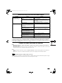
Utilisez ce climatiseur dans la plage de température suivante.
Plage de température intérieure :
Mode de refroidissement 14°C ~ 25°C (*TBH) / 18°C ~ 32°C (*TBS)
Mode de chauffage 16°C ~ 30°C (*TBS)
Plage de température extérieure :
Mode de refroidissement -15°C ~ 46°C (*TBS)
*1 -10°C ~ 43°C (*TBS)
Mode de chauffage -20°C ~ 18°C (*TBH) / -20°C ~ 24°C (*TBS)
*1 -15°C ~ 18°C (*TBH) / -15°C ~ 24°C (*TBS)
* TBS : (Température Boule Sèche)
* TBH : (Température Boule Humide)
* 1 Lors du branchement de U-60PEY1E5, U-71PEY1E5
Avis aux utilisateurs concernant la collecte et l’élimination des piles et des appareils électriques et
électroniques usagés
Apposé sur le produit lui-même, sur son emballage, ou fi gurant dans la documentation qui l’accompagne, ce
pictogramme indique que les piles et appareils électriques et électroniques usagés doivent être séparés des
ordures ménagères.
Afi n de permettre le traitement, la valorisation et le recyclage adéquats des piles et des appareils usagés,
veuillez les porter à l’un des points de collecte prévus, conformément à la législation nationale en vigueur
ainsi qu’aux directives 2002/96/CE et 2006/66/CE. En éliminant piles et appareils usagés conformément à
la réglementation en vigueur, vous contribuez à prévenir le gaspillage de ressources précieuses ainsi qu’à
protéger la santé humaine et l’environnement contre les effets potentiellement nocifs d’une manipulation
inappropriée des déchets.
Pour de plus amples renseignements sur la collecte et le recyclage des piles et appareils usagés, veuillez
vous renseigner auprès de votre mairie, du service municipal d’enlèvement des déchets ou du point de vente
où vous avez acheté les articles concernés. Le non-respect de la réglementation relative à l’élimination des
déchets est passible d’une peine d’amende.
Pour les utilisateurs professionnels au sein de l’Union européenne
Si vous souhaitez vous défaire de pièces d’équipement électrique ou électronique, veuillez vous renseigner
directement auprès de votre détaillant ou de votre fournisseur.
[Information relative à l’élimination des déchets dans les pays extérieurs à l’Union européenne]
Ce pictogramme n’est valide qu’à l’intérieur de l’Union européenne. Pour connaître la procédure applicable
dans les pays hors Union Européenne, veuillez vous renseigner auprès des autorités locales compétentes ou
de votre distributeur.
Note relative au pictogramme à apposer sur les piles (voir les 2 exemples ci-contre)
Le pictogramme représentant une poubelle sur roues barrée d’une croix est conforme à la réglementation.
Si ce pictogramme est combiné avec un symbole chimique, il remplit également les exigences posées par la
Directive relative au produit chimique concerné.
Pb
02_85464609230020_FR.fm Page 18 Thursday, December 27, 2012 4:23 PM

19
OPERATIONS
Nom des pièces
UNITÉ INTÉRIEURE
Télécommande sans fil (pièces en
option)
Reportez-vous au Mode d’emploi qui accompagne
la télécommande sans fil en option.
Télécommande de minuterie (pièces en
option)
Reportez-vous au Mode d’emploi qui accompagne
la télécommande de minuterie en option.
Boulon de
suspension
Matériau du
plafond
Boulon d’ancrage
Conduit de sortie
d’air
Unité intérieure
Grille de sortie
d’air
Type U1 (CASSETTE 4 VOIES)
Type F1 (CONDUIT SILHOUETTE BASSE)
Type N1 (CONDUIT)
Drain
Panneau de
plafond
(en option)
Sortie d’air
(4 emplacements)
Grille de
l’arrivée d’air
(arrivée d’air)
Type Y1 (CASSETTE 4 VOIES 60×60)
Drain
Panneau de plafond
(en option)
Sortie d’air
(4 emplacements)
Grille de
l’arrivée d’air
(en option)
Type T1 (PLAFOND)
Arrivée d’air
Sortie d’air
Type K1 (MONTE AU MUR)
Drain
(Vous pouvez
connecter le
tuyau de vidange
du côté droit ou
du côté gauche.)
Grille de
l’arrivée d’air
(en option)
Sortie d’air
(Type sans fil : pour
commander n’importe quel
type de l’unité intérieure)
REMARQUE
(Type avec fil : pour
commander n’importe quel
type de l’unité intérieure)
REMARQUE
02_85464609230020_FR.fm Page 19 Thursday, December 27, 2012 4:23 PM

20
RÉGLAGE DU FLUX D’AIR
Les fonctions varient en fonction de l’unité intérieure utilisée. La direction du flux d’air ne peut
pas être réglée à l’aide de la télécommande pour les unités listées ci-dessous.
Type U1, type Y1, type T1 et type K1.
• Ne jamais déplacer manuellement le volet contrôlé par la télécommande (volet de
circulation d’air vertical).
• Lorsque le climatiseur est mis hors tension, le volet (volet de circulation d’air vertical) se
déplace automatiquement vers le bas.
• Le volet (volet de flux d’air vertical) se déplace vers le haut lorsque le climatiseur est mis en
attente chauffage. Le balancement du volet commence à la fin d’attente du chauffage, mais
le balancement est indiqué sur la télécommande même pendant l’attente de chauffage.
Réglage de la direction
du flux d’air
La direction du flux d’air change chaque fois que le bouton FLAP est appuyé pendant
le fonctionnement.
Pour activer le
balancement
du volet
Appuyez sur le bouton FLAP pour régler le volet (volet de flux d’air vertical) vers le bas, puis
appuyez à nouveau sur le bouton FLAP. Ceci affiche et le flux d’air balaye de haut en bas
et vice versa automatiquement.
Pour arrêter le
balancement
du volet
Appuyez sur le bouton FLAP une nouvelle fois pendant le balancement du volet pour arrêter le
volet dans la position souhaitée. Ensuite, le flux d’air peut être réglé en position supérieure en
appuyant à nouveau sur le bouton FLAP.
Voyant lorsque le balancement est arrêté
Pendant le refroidissement et le séchage, le volet ne s’arrête pas orienté vers le bas. Même si
le bouton FLAP est appuyé pendant le balancement du volet, alors qu’il se trouve orienté vers
le bas pendant le balancement, il ne s’arrête pas jusqu’à ce qu’il se mette dans la troisième
position en partant du haut.
Chauffage Refroidissement et séchage Utilisation du
ventilateur
Toutes opérations
Réglez le volet (volet de flux d’air vertical) vers le
bas. Si le volet est réglé en position haute, l’air
chaud risque de ne pas atteindre le sol.
Le volet (volet de flux d’air vertical)
peut être réglé sur trois positions
différentes.
Réglage initial
Réglage initial
Réglage initial
Fonctionnement
continu
Ventilation et chauffage Refroidissement et séchage
02_85464609230020_FR.fm Page 20 Thursday, December 27, 2012 4:23 PM
La pagina si sta caricando...
La pagina si sta caricando...
La pagina si sta caricando...
La pagina si sta caricando...
La pagina si sta caricando...
La pagina si sta caricando...
La pagina si sta caricando...
La pagina si sta caricando...
La pagina si sta caricando...
La pagina si sta caricando...
La pagina si sta caricando...
La pagina si sta caricando...
La pagina si sta caricando...
La pagina si sta caricando...
La pagina si sta caricando...
La pagina si sta caricando...
La pagina si sta caricando...
La pagina si sta caricando...
La pagina si sta caricando...
La pagina si sta caricando...
La pagina si sta caricando...
La pagina si sta caricando...
La pagina si sta caricando...
La pagina si sta caricando...
La pagina si sta caricando...
La pagina si sta caricando...
La pagina si sta caricando...
La pagina si sta caricando...
La pagina si sta caricando...
La pagina si sta caricando...
La pagina si sta caricando...
La pagina si sta caricando...
La pagina si sta caricando...
La pagina si sta caricando...
La pagina si sta caricando...
La pagina si sta caricando...
La pagina si sta caricando...
La pagina si sta caricando...
La pagina si sta caricando...
La pagina si sta caricando...
La pagina si sta caricando...
La pagina si sta caricando...
La pagina si sta caricando...
La pagina si sta caricando...
La pagina si sta caricando...
La pagina si sta caricando...
La pagina si sta caricando...
La pagina si sta caricando...
La pagina si sta caricando...
La pagina si sta caricando...
La pagina si sta caricando...
La pagina si sta caricando...
La pagina si sta caricando...
La pagina si sta caricando...
La pagina si sta caricando...
La pagina si sta caricando...
La pagina si sta caricando...
La pagina si sta caricando...
La pagina si sta caricando...
La pagina si sta caricando...
La pagina si sta caricando...
La pagina si sta caricando...
La pagina si sta caricando...
La pagina si sta caricando...
La pagina si sta caricando...
La pagina si sta caricando...
La pagina si sta caricando...
La pagina si sta caricando...
La pagina si sta caricando...
La pagina si sta caricando...
La pagina si sta caricando...
La pagina si sta caricando...
La pagina si sta caricando...
La pagina si sta caricando...
La pagina si sta caricando...
La pagina si sta caricando...
La pagina si sta caricando...
La pagina si sta caricando...
La pagina si sta caricando...
La pagina si sta caricando...
La pagina si sta caricando...
La pagina si sta caricando...
La pagina si sta caricando...
La pagina si sta caricando...
La pagina si sta caricando...
La pagina si sta caricando...
La pagina si sta caricando...
La pagina si sta caricando...
La pagina si sta caricando...
La pagina si sta caricando...
La pagina si sta caricando...
La pagina si sta caricando...
La pagina si sta caricando...
La pagina si sta caricando...
La pagina si sta caricando...
La pagina si sta caricando...
La pagina si sta caricando...
La pagina si sta caricando...
La pagina si sta caricando...
La pagina si sta caricando...
La pagina si sta caricando...
La pagina si sta caricando...
La pagina si sta caricando...
La pagina si sta caricando...
La pagina si sta caricando...
La pagina si sta caricando...
La pagina si sta caricando...
La pagina si sta caricando...
La pagina si sta caricando...
La pagina si sta caricando...
La pagina si sta caricando...
La pagina si sta caricando...
La pagina si sta caricando...
La pagina si sta caricando...
La pagina si sta caricando...
La pagina si sta caricando...
La pagina si sta caricando...
La pagina si sta caricando...
La pagina si sta caricando...
La pagina si sta caricando...
La pagina si sta caricando...
La pagina si sta caricando...
-
 1
1
-
 2
2
-
 3
3
-
 4
4
-
 5
5
-
 6
6
-
 7
7
-
 8
8
-
 9
9
-
 10
10
-
 11
11
-
 12
12
-
 13
13
-
 14
14
-
 15
15
-
 16
16
-
 17
17
-
 18
18
-
 19
19
-
 20
20
-
 21
21
-
 22
22
-
 23
23
-
 24
24
-
 25
25
-
 26
26
-
 27
27
-
 28
28
-
 29
29
-
 30
30
-
 31
31
-
 32
32
-
 33
33
-
 34
34
-
 35
35
-
 36
36
-
 37
37
-
 38
38
-
 39
39
-
 40
40
-
 41
41
-
 42
42
-
 43
43
-
 44
44
-
 45
45
-
 46
46
-
 47
47
-
 48
48
-
 49
49
-
 50
50
-
 51
51
-
 52
52
-
 53
53
-
 54
54
-
 55
55
-
 56
56
-
 57
57
-
 58
58
-
 59
59
-
 60
60
-
 61
61
-
 62
62
-
 63
63
-
 64
64
-
 65
65
-
 66
66
-
 67
67
-
 68
68
-
 69
69
-
 70
70
-
 71
71
-
 72
72
-
 73
73
-
 74
74
-
 75
75
-
 76
76
-
 77
77
-
 78
78
-
 79
79
-
 80
80
-
 81
81
-
 82
82
-
 83
83
-
 84
84
-
 85
85
-
 86
86
-
 87
87
-
 88
88
-
 89
89
-
 90
90
-
 91
91
-
 92
92
-
 93
93
-
 94
94
-
 95
95
-
 96
96
-
 97
97
-
 98
98
-
 99
99
-
 100
100
-
 101
101
-
 102
102
-
 103
103
-
 104
104
-
 105
105
-
 106
106
-
 107
107
-
 108
108
-
 109
109
-
 110
110
-
 111
111
-
 112
112
-
 113
113
-
 114
114
-
 115
115
-
 116
116
-
 117
117
-
 118
118
-
 119
119
-
 120
120
-
 121
121
-
 122
122
-
 123
123
-
 124
124
-
 125
125
-
 126
126
-
 127
127
-
 128
128
-
 129
129
-
 130
130
-
 131
131
-
 132
132
-
 133
133
-
 134
134
-
 135
135
-
 136
136
-
 137
137
-
 138
138
-
 139
139
-
 140
140
-
 141
141
-
 142
142


Panasonic U71PEY1E5 Manuale del proprietario
- Tipo
- Manuale del proprietario
in altre lingue
Documenti correlati
-
Panasonic U125PEY1E8 Istruzioni per l'uso
-
-
Panasonic S36MY2E5 Manuale del proprietario
-
Panasonic S28MK2E5A Istruzioni per l'uso
-
Panasonic S160MU1E5A Istruzioni per l'uso
-
-
Panasonic S-45MT1E5 Manuale del proprietario
-
-
-
Panasonic S36PK1E5A Istruzioni per l'uso