Shindaiwa DH230-30 Manuale utente
- Categoria
- Tagliasiepi a motore
- Tipo
- Manuale utente
Questo manuale è adatto anche per

GB
FR
IT
ENGLISH
(Original instructions)
FRANÇAIS
(Notice originale)
ITALIANO
(Istruzioni originali)
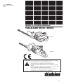
SHINDAIWA OWNER’S/OPERATOR’S MANUAL
HT230/DH230 HEDGE TRIMMER
HT230
DH230
WARNING
!
●
Read this manual and familiarize yourself with its contents.
●
This machine is designed for trimming hedges.
●
Do not use this machine for other purposes.
●
Minimize the risk of injury to yourself and others.
●
Do not operate or service this machine unless you clearly
understand this manual.
●
Keep this manual accessible so that you can reread it
whenever you have a question about its use.

2
Introduction
The Shindaiwa HT230/DH230
series of hand power tools has been
designed and built to deliver superior
performance and reliability without
compromise to quality, comfort, or
durability. Shindaiwa high performance
engines represent the leading edge of
2-cycle engine technology, delivering
exceptionally high power at remarkable
low displacement and weight. As an
owner/operator, you’ll soon discover for
yourself why Shindaiwa is simply in a
class by itself!
IMPORTANT!
The information contained in this manual
describes machines available at the time
of publication.
While every attempt has been made
to give you the very latest information
about your Shindaiwa product, there
may be some differences between
your machine and what is described
here. Shindaiwa reserves the right to
make changes to products without
prior noti¿ cation, and without obligation
to make alterations to machines
previously manufactured.
Contents
PAGE
Introduction ....................................... 2
Attention Statements ........................ 2
Safety Precautions ........................... 3
General Safety Instructions .............. 4
Operational Precautions ................... 5
Operating the Hedge Trimmer .......... 5
Speci¿ cations ................................... 6
Product Description .......................... 6
Assembly .......................................... 7
Throttle Cable Adjustment ................ 9
Mixing Fuel ....................................... 9
Filling the Fuel Tank ........................ 10
Starting Procedure.......................... 10
Starting a Flooded Engine ...............11
Stopping the Engine ....................... 12
Engine Idle Adjustment ................... 12
General Maintenance ..................... 12
Long Term Storage ......................... 14
MufÀ er Maintenance ....................... 15
Cutter Blade Adjustment ................. 15
Troubleshooting Guide ................... 16
Declaration of Conformity ............... 19
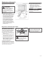
Attention Statements
Throughout this manual are Special
“attention statements” Surrounded by
boxes and preceded by the triangular
Attention Symbol.
WARNING!
A statement preceded by
the triangular attention
symbol and the word “WARNING”
contains information that should
be acted upon to prevent serious
bodily injury.
CAUTION!
A statement preceded by the word
“CAUTION” contains information
that should be acted upon to prevent
mechanical damage.
IMPORTANT!
A statement preceded by the word
“IMPORTANT” is one that possesses
special signi¿ cance.
NOTE:
A statement preceded by the word
“NOTE” contains information that is
handy to know and may make your job
easier.
Read and follow this
manual and make
sure anyone using
the hedge trimmer
does likewise. Failure
to do so could result
in serious in-jury or
machine failure. Keep
this manual for future
reference.
Always wear eye and
hearing protection
during the operation
of this hedge trimmer.
A hard hat will provide
additional security
against falling debris.
Sound Power
Level (measure in
accordance with
2000/14/EC)
IMPORTANT!
The operational procedures described
in this manual are intended to help you
get the most from your machine, and
to protect you and others from harm.
These procedures are guidelines for
safe operation under most conditions,
and are not intended to replace any
safety rules and/or laws that may
be in force in your area. If you nave
questions regarding your machine, or
if you do not understand something in
this manual, your Shindaiwa dealer will
be glad to assist you.

3
Safety Precautions
WARNING!
■
Do not operate the hedge
trimmer if you are tired, ill, or
under the inÀ uence of alcohol,
drugs, or medication.
■
Keep bystanders at least
5 meters (15 feet) away from the
working area during operation to
reduce their risk of being cut by
the cutters of struck by thrown
debris. Stop working immediately
if a person, especially a small
child or animal comes within the
5 meters zone.
■
The blades are sharp-handle
them with care! Wearing
heavyduty gloves will go a long
way toward protecting your
hands.
■
Keep your hands clear of the
cutter blades when starting the
engine, and anytime the engine
is running.
■
THIS MACHINE CAN CAUSE
SERIOUS INJURIES. Read
the instructions carefully for the
correct handling, preparation,
maintenance, starting and
stopping of the machine. Be
familiar with all controls and the
proper use of the machine.
WARNING!
THE HEDGE TRIMMER
IS NOT INSULATED
AGAINST ELECTRICAL SHOCK!
Approaching of contacting an
electric fence, power line or other
electri¿ ed object could cause death
or serious injury.
Keep the hedge trimmer at least
10 meters (33 feet) away from
electri¿ ed objects or branches that
contact them.
WARNING!
The engine exhaust from
this product contains
substances which are harmful to
your health.
WARNING!
The blades are SHARP!
Handle with care.
Keep hands clear of the cutter
blades when starting the engine.
Do not operate this machine if you
are tired, ill, or under the inÀ uence
of alcohol, drugs, or medicine.

4
General Safety Instructions
Note the locations of fence posts and
other ¿ xed objects and avoid cutting
them.
Inspect the cutting site thoroughly
prior to operation. Remove objects
that could get entangled by the
cutter blade.
Avoid cutting large or
extremely woody branches.
Doing so can shorten cutter
life and damage the gearcase.
Always operate with both hands
¿ rmly gripping the handgrips of the
machine.
Do not allow the cutters to
contact buildings or other hard
objects during operation.
Never operate this
machine if any safety
guards are missing or
damaged.
If a cutter should bind
fast in a cut, stop the
engine immediately.
Remove the cause of the
bind before proceeding.
Never cut metal objects
or wire with the blade.
Always keep a proper footing and do not overreach.
Maintain your balance at all times during operation especially when
using steps or a ladder.
Wear appropriate footwear such as non-skid boots or shoes.
Never work barefooted or wear open-toed shoes or sandals.
Always be aware of your surroundings
and stay alert for possible hazards that
you may not hear due to the noise of the
machine.
Never allow children to use the
machine. Avoid operating near
bystanders.
Avoid long-term operation
in very hot or very cold
weather.
Always wear hearing protection such
as earmuffs or earplugs.
Always wear eye protection such as
goggles or safety glasses.
Before moving to another
job site, stop the engine and
install the blade cover.
Secure long hair so it is above
shoulder level.
Non-skid gloves provide a ¿ rm grip,
added protection to your hands,
and are strongly recommended.
Do not wear jewelry or loose
clothing that could get caught
in machinery or brush.
Make sure handgrips
are free of forign
substances such as
lubricant and pitch.
Wear appropriate clothing. It should
¿ t snugly to minimize snagging yet
permit free movement. Never wear
shorts when operating the hedge
trimmer.

5
WARNING!
■
NEVER allow any person to
operate this hedge trimmer who
has not been properly trained or
instructed.
■
NEVER smoke or light ¿ res
near the hedge trimmer. Keep
the hedge trimmer away from
excessive heat. Engine fuel is
very À ammable!
■
Before starting the engine move
3 meters (10 feet) away from the
fuel storage area or other readily
À ammable materials. Do not put
À ammable materials close to the
mufÀ er.
■
NEVER run the engine indoors,
Make sure there is always good
ventilation when running the
engine. Engine exhaust contains
deadly poisonous carbon
monoxide gas.
■
ALWAYS stop the engine before
refueling, and let the engine cool
before refueling.
■
Do not over¿ ll the fuel tank. Wipe
off any spilled fuel immediately.
After refueling, inspect the tank
to make sure its cap is threaded
on properly. Make sure there are
no fuel leaks.
■
Stop the engine immediately
if the hedge trimmer suddenly
begins to vibrate or shake.
Inspect for broken, missing, or
improperly installed parts or
components. Correct the problem
before returning the hedge
trimmer to service.
■
ALWAYS disconnect the spark
plug wire before performing any
maintenance work.
■
ALWAYS maintain the hedge
trimmer according to this
owner’s manual and follow the
recommended maintenance
schedule.
■
NEVER modify or disable any
of the hedge trimmer’s safety
devices.
■
ALWAYS use genuine Shindaiwa
parts and accessories when
repairing or maintaining
this hedge trimmer. These
components have been
manufactured speci¿ cally for
use on this unit and meet the
speci¿ cations for performance
and safety.
■
Make sure the cutters are
correctly adjusted before
operating the hedge trimmer.
■
NEVER attempt to adjust the
cutter with the engine running.
■
NEVER use a cracked or broken
cutter or cutter bar; replace it
with a new or serviceable one.
■
Make suer the powerhead is
clean and that the engine cooling
¿ ns and mufÀ er are unobstructed
and free of debris and loose
vegetation.
■
Do not operate the hedge
trimmer with the mufÀ er
removed.
■
When transporting or storing the
hedge trimmer, make sure the
blade cover is attached to the
cutter.
■
Always ensure all handles and
guards are attached and secure
when using the machine.
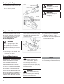
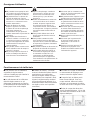
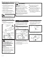
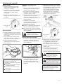
Operation of the Hedge Trimmer
■ Squeezing the throttle increases
engine speed, causing the clutch to
engage and operate the cutters.
■ Releasing the throttle decreases
engine speed, causing the cutters to
slow, and then stop altogether as the
clutch disengages.
■ Speed adjustment, turning the
maximum speed adjustment dial
counterclockwise decreases the
engine speed when the throttle is
fully squeezed. Adjust the maximum
engine speed to suit your work.
(The maximum speed adjustment
dial is preset on its maximum speed
position at the factory.)
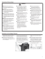
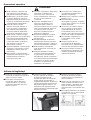
■ Use a sweeping motion when
cutting, and vary throttle settings
often.
■ Trim the hedge swinging the blade
as the illustration shows. At vertical
cutting the hedge trimmer is used
with circular pendulation, swingign
up and down close to the hedge.
■ Avoid cutting material larger than
1.2 cm (1/2 inch) in diameter. Do not
cut metal objects or wire.
Operational Precautions
Reduce Speed

6
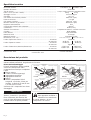
Speciæ cations
Model Name ......................................................................................................... HT230/EC1-30 | DH230/EC1-24
Engine Model........................................................................................................ SHT230EC
Engine Type .......................................................................................................... 2-cycle, horizontal cylinder, air cooled
Dry Weight (excluding cutting attachment) ........................................................... 5.6 kg | 5.7kg
Bore x Stroke ........................................................................................................ 32 mm x 28 mm
Displacement ........................................................................................................ 22.5 cm
3
Engine Speed at Maximum Power Output ........................................................... 8,000 min
-1
(rpm)
Maximum Power Output ....................................................................................... 0.75 kW
Engine Speed at Idling ......................................................................................... 3,000 min
-1
(rpm)
Maximum Engine Speed ...................................................................................... 11,500 min
-1
(rpm)
Fuel/Oil Ratio ........................................................................................................ 50:1
Fuel Tank Capacity ............................................................................................... 600 cm
3
Carburator ............................................................................................................ Walbro, WYJ
Ignition System ..................................................................................................... Fully Electronic, transistor controlled
Spark Plug ............................................................................................................ NGK BMR6A
Air Cleaner............................................................................................................ Semi-wet Type
Starting Method .................................................................................................... Recoil Starter
Stopping Method .................................................................................................. Slide Switch
Dimensions (L x W x H) ........................................................................................
1070 x 260 x 220 mm | 1080 x 250 x 210
mm
Sound Pressure Level * ................................................................................Idling 74 dB (A)
Racing 96 dB (A) | 97 dB (A)
Sound Power Level * ....................................................................................Idling 84 dB (A) | 86 dB | (A)
...................................................................................................................Racing 105 dB (A)
Vibration Level (Front/Rear) * .......................................................................Idling 5.7/6.5 m/s
2
| 3.8/4.8 m/s
2
Racing 6.8/8.7 m/s
2
| 7.2/10.7 m/s
2
* Sound Pressure Level: in accordance with ISO 11201 * Sound Power Level: in accordance with ISO 3744
* Vibration Level: in accordance with EN 28662-1
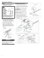
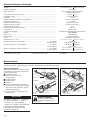
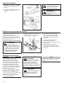
Product Description
Familiarize yourself with your machine and its various components. Understanding your machine helps ensure top
performance, long service life, and safer operation.
Prior to Assembly
Before assembling this product,
please make sure you have all the
components required for a complete
unit:
■ Engine assembly (powerhead)
■ Cutter and gearcase assembly
■ Rear handle
■ Front handle
■ Bolt package
■ Tool kit including, allen wrenches,
screwdriver, combination spark
plug/13 mm wrench, 8 mm and
10 mm wrench (HT230 only).
Carefully inspect all components for
damage.
IMPORTANT!
The terms “left,” “left-hand,” and “LH”;
“right-hand,” and “RH”; “front” and “rear”
refer to directions as viewed by the
operator during normal operation of this
product.
WARNING!
Do not make unauthorized
modi¿ cations or alterations
to this machine or any of its
components or accessories.
Front Handle
Front Handle
Recoil Starter
Recoil Starter
Guide Bar
Guide Bar
Cutter
Cutter
Safety Guard
Safety Guard
Speed Adjustment Dial
MufÀ er
Throttle
Throttle
Trigger
Cover
Cover
ON-OFF
Switch
ON-OFF
Switch
Fuel Cap
Fuel Cap
Protector
Fuel Tank
Fuel Tank
Gearcase
Air Cleaner Cover
Air Cleaner Cover
Choke
Choke
Rear Handle
Rear
Handle
HT230
DH230

7
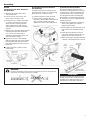
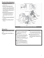
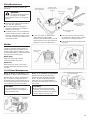
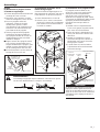
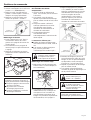
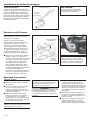
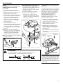
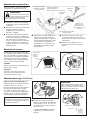
Assembly
HT230
(a) Attaching the Rear Handle to
the Gearcase
1) Temporarily remove the 5mm x
12mm index bolt.
2) Loosen, but do not remove, the
5mm x 25mm clamp screw.
3) Position the rear handle assembly
as shown. Starting from the rear
of the trimmer, push the throttle
cable, ignition wire, and ground
wire through the handle mounting
bracket.
4) Slide the rear handle into the handle
mounting bracket until it bottoms.
Use care to avoid pinching or
otherwise damaging the wires and
cable installed in Step 3.
■ Align the hole in the rear handle
with the matching hole in the handle
mounting bracket, and then install
and ¿ rmly tighten the 5mm x 12mm
index bolt.
■ Tighten the 5mm x 25mm clamp
screw ¿ rmly.
(c) Install the Front Handle
The front handle is installed over a
5mm stud on the guide bar, as well as
a special 6mm x 30mm shoulder bolt
assembly that is also used for guide
bar adjustment. When installing the
front handle, it is extremely important
to maintain correct bar adjustment as
described below:
1) Install the 5mm À ange nut over the
stud on the guide bar, and then
tighten the nut ¿ rmly.
2) Hand-tighten the shoulder bolt, and
then loosen the shoulder bolt 1/2-
turn.
3) Install the 6mm washer and lock
nut on the shoulder bolt but do not
tighten the lock nut at this time.
4) While holding the shoulder bolt with
a wrench, ¿ rmly tighten the lock nut.
IMPORTANT!
Improper shoulder bolt adjustment can
shorten gearcase life drastically! Blade
durability and cutting performance are
affected by shoulder bolt adjustment.
(b) Installing the Powerhead on
the Gearcase
Orient the gearcase assembly to the
powerhead as shown, and secure with
the three 6mm x 16mm screws.
1) Securely tighten Screws A and B.
2) Push Screw C through the eye
terminal in the throttle control ground
wire, and then install and ¿ rmly
tighten the screw to the powerhead.
Throttle Cable,
Ignition, and
Ground Wires
Rear Handle
Assembly
Clamp Screw
Index Bolt
Powerhead
Screw C
Screw A
and B
5mm
Flange
Nut
Stud
Shoulder Bolt
(adjust from below)
Front
Handle
6mm Nut
and Washer
WARNING!
Incorrect assembly could expose the operator to serious injury! Read
and follow assembly instructions carefully.

8
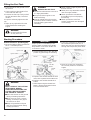
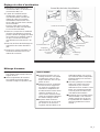
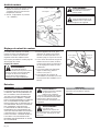
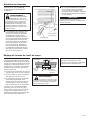
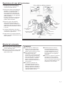
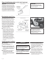
Assembly (continued)
DH230
(1) Attaching the Rear Handle to
the Gearcase Assembly
1) Slide the rear handle onto the
rear À ange of the cutter/gearcase
assembly. Make sure the throttle
cable and ignition and ground wires
do not bind during assembly.
2) Make sure the mating holes
between the rear handle and the
gearcase are aligned, then secure
the rear handle using two 6mm x
35mm socket head cap screws and
washers.
(2) Install the Front Handle
1) Locate the front handle onto the
cutter/gearcase assembly as shown.
2) Secure the handle using two 6mm x
35mm socket head capscrews and
washers.
(3) Installing the Powerhead on
the Gearcase
Orient the gearcase assembly and
powerhead as shown and secure
with the three 6mm x 16mm screws
(Screws A, B, and C).
1) Securely tighten Screws A and B.
2) Push Screw C through the eye
terminal in the throttle control
ground wire (black), and then install
and ¿ rmly tighten the screw to the
powerhead.
IMPORTANT!
The washers used on the front handle
and the rear handle are not the same.
The washers for the rear handle are
black for identi¿ cation.
WARNING!
Incorrect
assembly
could expose
the operator
to serious
injury! Read
and follow
assembly
instructions
Before attaching the rear handle,
make sure the rear handle
cushions are located correctly.
Cushion
Collar
Rear
Handle
Cushion
Viewed from
the bottom
Powerhead
Screws A and B
(6 x 16mm)
Rear Handle
Assembly
Cutter/Gearcase
Assembly
6mm x 35mm
Socket Head
Capscrews and
Washers (washers
black for identi¿ cation)
Screws C
(6 x 16mm)
Front Handle
6mm Socket Head
Capscrews and Washers
Throttle Cable,
Ignition and
Ground Wires

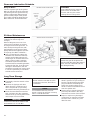
9
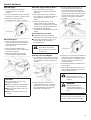
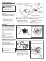
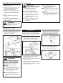
Throttle Cable Adjustment
Mixing Fuel
■ When mixing fuel, combine 2-cycle
Engine Oil with gasoline at a ratio of
50:1.
■ Use only fresh, clean unleaded
gasoline with an octane rating of 87
or above.
1) Loosen the air cleaner cover
retaining screw, and remove the air
cleaner cover.
2) Working from the bottom of the
trimmer, push the throttle cable
through the cable adjustment ¿ tting.
Rotate the carburetor throttle about
45° and place the cable terminal in
the throttle ¿ tting. Install the clip after
¿ xing the throttle cable terminal to
the throttle ¿ tting.
3) Measure free play at the end of
the throttle lever. If necessary, turn
the cable adjustment ¿ tting in or
out until throttle lever free play is
approximately 5-10mm (0.2-0.4
inch).
4) Firmly connect the two ignition wires
as shown and tuck the wire behind
the gasket.
5) Replace the air cleaner cover, and
tighten the cover retaining screw
securely.
CAUTION!
■
This engine is certi¿ ed to operate
on a 50:1 mixture consisting of
unleaded gasoline and 2-cycle
mixing oil only.
■
Some motor fuels contain alcohol
as an oxygenate! Oxygenated fuels
may cause increased operating
temperatures. Under certain
conditions, alcohol-based fuels may
also reduce the lubricating qualities
of some mixing oils.
■
Never use any fuel containing
more than 10% alcohol by volume!
When an oxygenated fuel must be
used, a fuel containing MTBE is to
be preferred over an alcohol based
fuel.
■
Generic oils and some outboard
motor oils may not be intended for
use in high-performance air cooled
2-cycle engines, and should never
be used in your Shindaiwa trimmer!
■
Mix only enough fuel for your
immediate needs! If fuel must be
stored linger than 30 days, it should
¿ rst be treated with a stabilizer such
as StaBil™.
Throttle Fitting
Air Cleaner Cover
Throttle Cable
Adjuster
Ground Wire
Screw C
The Hedge Trimmer Should now be assembled.
Ignition Wire
(red)
Gasket
Ignition Wire
Connection
Throttle Cable
Terminal
Throttle Lever Free Play
HT230 DH230
5 ~ 10mm
(0.2 ~ 0.4")
5 ~ 10mm
(0.2 ~ 0.4")
Clip

10
Filling the Fuel Tank
1. Place the unit on the ground or on a
À at surface.
2. Clear any dirt or other debris from
around the fuel ¿ ller cap.
3. Remove the fuel cap slowly, and ¿ ll
the fuel tank with clean, fresh fuel
mixture.
4. Replace and ¿ rmly tighten the fuel
cap.
5. Wipe up any spilled fuel from the
powerhead before starting the
engine
WARNING!
De net inhale fuel fumes
as they are toxic!
Starting Procedure
Control Positions (Cold Engine)
1. Move the ignition switch rearward to
the “T” or START position.
WARNING!
KEEP CLEAR OF THE CUTTING
ATTACHMENT DURING
STARTING OPERATIONS! THE
CUTTERS MAY MOVE WHEN
THE ENGINE IS STARTED
■
Place the trimmer on the ground
during all starting operations.
■
Make sure you have a secure
footing, and keep a ¿ rm grip on
the machine as well.
■
Keep all bystanders and pets
well clear of the trimmer during
starting operations.
IMPORTANT!
Engine ignition is controlled by a two-
position switch mounted on the throttle
body labeled “T” for ON or START and
“0” for OFF or STOP.
2. Set the throttle lever to the “fast idle”
position by performing the following.
a. Depress and hold the throttle lockout
lever, then squeeze the throttle lever.
b. Depress and hold the throttle lock
button.
c. While depressing the throttle lock
button, release the throttle lockout
lever and throttle lever.
3. Prime the carburetor by depressing
the carburetor primer bulb 4 or 5
times until you see clear fuel À owing
through the transparent primer bulb.
4. Move the choke lever forward to
the “closed” position to choke the
engine.
WARNING!
Minimize the risk of ¿ re!
■
Handle fuel with extreme care since
it is highly À ammable!
■
Always allow the engine to cool
before refueling!
■
Wipe all spilled fuel and move the
machine at least 3 meters (10 feet)
from the fueling point before
restarting!
■
Never smoke or light any ¿ res near
the unit or fuels!
■
Never place any À ammable material
near the engine mufÀ er!
■
Never operate the unit without
the mufÀ er in place and properly
functioning!
■
Never operate the unit if fuel
system components are damaged
or are leaking.
HT230
HT230
DH230
DH230
Ignition ON
Ignition Switch
Throttle
Lock
Fast Idle
Button
Primer Bulb
(viewed from rear)
Choke Closed
Fast Idle
Button
Throttle
Lock
Throttle Trigger
Throttle
Trigger
Ignition ON
Ignition
Switch

11
(Warm Engine)
1. Move the ignition stop switch
rearward to the ‘T’ or START
position.
2. Set the throttle lever to the “fast idle”
position as in Step 2, previous page.
3. Move the choke lever back
(rearward) to the “open” position.
Start the Engine
1. Place the machine on the ground.
Grip the engine cover with your left
hand and the starter handle with
your right hand.
2. Pull the starter handle slowly
toward you until you feel the starter
mechanism engage.
3. Start the trimmer by pulling the
starting handle rapidly outward.
CAUTION!
The recoil starter can be easily
damaged by abuse.
■
Always engage the starter before
attempting to crank the engine.
■
Never pull the starter cord to its
full length.
■
Always rewind the starter cord
slowly.
When the engine starts or æ res...
1. Open the choke by moving the
choke lever backward (toward the
fuel tank).
2. If the engine does not continue to
run, repeat the appropriate starting
procedures for a cold or warm
engine.
3. When the engine starts, clear
excess fuel from the combustion
chamber by accelerating the engine
several times with the throttle lever.
4. Operating the throttle will
automatically disengage the fast idle
setting.
If the engine does not start
■ Repeat the appropriate starting
procedure for a cold or warm engine.
■ If the engine still fails to start, use
the procedures for “Starting a
Flooded Engine”.
WARNING!
The cutting attachment
will move when the engine
accelerates;
Starting a Flooded Engine
1. Disconnect the spark plug lead, then
use the spark plug wrench to remove
the spark plug (counterclockwise to
remove).
2. If the spark plug is fouled or is
soaked with fuel, clean or replace
the plug as necessary. For spark
plug speci¿ cations and gapping
procedure. See Page 13.
3. Set the ignition switch to the “O”
or STOP position and open the
choke. Fully depress the throttle
lever with your left hand and pull the
starter handle rapidly with your right
hand several times to clear excess
fuel from the engine combustion
chamber.
4. Replace the spark plug and tighten it
¿ rmly with the spark plug wrench. If
a torque wrench is available, torque
the spark plug to 16.7-18.6 N m
(170-190 kg-cm).
5. Repeat the starting procedures for a
warm engine.
6. If the engine still fails to start or ¿ re,
refer to the troubleshooting chart at
the end of this manual.
WARNING!
Move the ignition switch
forward to the “O” or STOP
position.
WARNING!
Burn danger from hot
engine! Allow engine to
cool before removing spark
plug.
CAUTION?
Incorrect spark plug installation can
result in serious engine damage!
Control Positions
Choke Open
STOP
Position
Choke Open
Cover
Spark Plug
Lead
Spark Plug

12
1. Cool the engine by allowing it to idle
for 2 - 3 minutes.
2. Move the ignition switch forward to
the “O” or STOP position.
The engine must return to idle speed
whenever the throttle lever is released.
Idle speed is adjustable, and must be
set low enough to permit the engine
clutch to disengage the cutters.
Idle Speed Adjustment
WARNING!
The cutters must NEVER
engage at engine idle
speeds! If the idle speed cannot
be adjusted by the procedure
described here, return the trimmer
to your dealer for inspection.
1. Place the unit on the ground, then
start the engine and allow it to idle
2-3 minutes until warm.
IMPORTANT!
MAINTENANCE, REPLACEMENT OR
REPAIR OF EMISSION CONTROL
DEVICES AND SYSTEMS MAY BE
PERFORMED BY ANY REPAIR
ESTABLISHMENT OR INDIVIDUAL;
HOWEVER, WARRANTY REPAIRS
MUST BE PERFORMED BY A DEALER
OR SERVICE CENTER AUTHORIZED
BY YAMABIKO CORPORATION THE
USE OF PARTS THAT ARE NOT
EQUIVALENT IN PERFORMANCE AND
DURABILITY TO AUTHORIZED PARTS
MAY IMPAIR THE EFFECTIVENESS OF
THE EMISSION CONTROL SYSTEM
AND MAY HAVE A BEARING ON THE
OUTCOME OF A WARRANTY CLAIM.
2. If the cutters move when the engine
is at idle, reduce idle speed by
turning the idle adjustment screw
counterclockwise.
3. If a tachometer is available, the
engine idle speed should be
adjusted to 3,000 min (rpm).
4. Carburetor fuel mixture adjustments
are preset at the factory and cannot
be serviced in the ¿ eld.
NOTE:
Using non-standard replacement parts
could invalidate your Shindaiwa warranty.
WARNING!
The cutters can continue
oscillating after the engine
is switched off.
WARNING!
Know how to stop the
machine quickly in an
emergency.
WARNING!
Before performing any
maintenance, repair or
cleaning work on the unit, make
sure the engine and cutting
attachment are completely
stopped. Disconnect the spark plug
wire before performing service or
maintenance work.
WARNING!
Non-standard parts may
not operate properly with
your unit and may cause damage
and lead to personal injury.
Stopping the Engine
Engine Idle Adjustment
General Maintenance
HT230
DH230
Ignition Switch
Ignition Switch
Reduce Idle
Speed
Idle Adjustment Screw
Ignition Stop (O)
Ignition Stop (O)

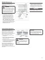
13
Prior to each work day, perform the
following:
WARNING!
To reduce ¿ re hazard, keep
the engine and mufÀ er
free of debris, leaves, or excessive
grease.
■ Lubricate the cutters with oil before
use, and after refueling.
■ Check the cutters for damage or
improper adjustment, and adjust or
replace as necessary.
■ Carefully remove any accumulations
of dirt or debris from the mufÀ er and
fuel tank. Dirt build-up in these areas
can lead to engine overheating, ¿ re,
or premature wear.
This unit must never be operated with
a faulty or missing spark arrester or
mufÀ er. Make sure the mufÀ er is well
secured and in good condition. A worn
or damaged mufÀ er is a ¿ re hazard and
may also cause hearing loss.
Spark Plug
Keep the spark plug and wire
connections tight and clean.
Fasteners
Make sure nuts, bolts, and screws
(except carburetor adjusting screws)
are ¿ ght.
Every 10 hours of operation, (more
frequently in dusty or dirty conditions):
Remove the air cleaner element from
the air cleaner housing and clean it
thoroughly with soap and water. Rinse
and dry thoroughly. Add a few drops of
oil and work it in, then reassemble.
CAUTION!
Do not operate the unit if the air
cleaner or element is damaged, or
if the element is wet.
Every 10 to 15 hours of operation:
Remove and clean the spark plug.
Adjust the spark plug electrode gap
to 0.6 - 0.7mm. If the plug must be
replaced, use only: NGK BMR6A or
an equivalent spark plug of the correct
heat range.
CAUTION!
Before removing the spark plug,
clean the area around the plug to
prevent dirt and debris from getting
into the engine’s internal parts.
■ Clean any debris or dirt from the
hedge trimmer cutter blades.
Lubricate the blades before use and
after refueling. Check the cutters for
damage or incorrect adjustment.
■ Check for loose or missing screws
or components. Make sure the cutter
attachment is securely fastened.
■ Check the entire unit for leaking fuel
or grease.
Daily Maintenance
Mufç er
10-15 Hour Maintenance
Clean debris from
tank and mufÀ er
Inspect cooling
¿ ns, and clean as
required
Clean around
spark plug
Lubricate
cutters
Check cutters for
damage and correct
adjustment
Inspect/clean air ¿ lter
element
Keep intake
clean
Air Cleaner
Element
Air Cleaner
Cover
Clean the spark plug and check the
gap at the electrode.
Cover
Clean Debris
0.6 - 0.7mm
Keep cooling
¿ ns clean

14
Every 20 Hours
Connect a grease gun to the grease
¿ tting on the left side of the gearcase.
Top off the gearcase grease level by
adding a high quality lithium-based
grease. Three pumps of the grease
gun handle should be adequate. DO
NOT OVERFILL THE GEARCASE!
(more frequently in dusty or dirty
conditions or before long-term
storage):
Remove the gearcase cover. Use
solvent and a soft brush to remove
all old grease from the gearcase. To
re¿ ll, hand-pack the gearcase with
approximately 40-50 grams of high
quality lithium-based grease (50-70%
of capacity). DO NOT OVERFILL!
■ Use a hooked wire to extract the
fuel ¿ lter from inside the fuel tank.
Inspect the fuel ¿ lter element. If it
shows signs of contamination from
debris, replace it with a genuine
Shindaiwa replacement fuel ¿ lter
element. Before reinstalling the ¿ lter,
inspect the fuel line. If you discover
damage or deterioration, the unit
should be removed from service until
it can be inspected by a Shindaiwa-
trained service technician.
(30 days or longer)
■ Thoroughly clean the exterior of the
machine.
■ Remove all clippings and other
debris from the cylinder ¿ ns and
other components (as previously
described under Daily Maintenance).
■ Drain all unused fuel from the fuel
tank, and then clear the carburetor
and fuel lines by running the trimmer
until it stops from lack of fuel.
IMPORTANT!
All stored fuel should be stabilized with
fuel stabilizer such as STA-BIL™
■ Remove the spark plug, and pour
about 7 grams of 2-cycle mixing oil
into the cylinder through the spark
plug hole. Before reinstalling the
spark plug, slowly pull the recoil
starter 2-3 times to distribute the oil
over the cylinder wall.
■ Service the air cleaner element as
previously described in the daily
maintenance section of this manual.
■ Repair or replace any damaged
components as required, and then
store the unit in a dean, dry, and
dust-free area.
CAUTION!
Over-lubricating may cause the
gearcase to run slower than
normal, and may also cause
leakage from excess grease.
Gearcase Lubrication Schedule
50-Hour Maintenance
Long Term Storage
VIEWED FROM THE BOTTOM
Gearcase
Grease
Fitting
VIEWED FROM THE BOTTOM
DO NOT REMOVE
CONRODS!
Hooked
Wire
Filter Element
Socket-head
Capscrews
Gearcase
Cover
CAUTION!
Make sure you do not pierce the
fuel line with the end of the hooked
wire. The line is delicate and can
be damaged easily.
CAUTION!
Never store this unit with any fuel
remaining in the tank, fuel lines or
carburetor!
NOTE:
Your Shindaiwa warranty does not
include coverage for damage caused by
stale or contaminated fuels.

15
Seasonally (or whenever you
experience hard starting or poor
performance):
WARNING!
Never operate this machine
with a damaged or missing
mufÀ er or spark arrester? Operating
with missing or damaged exhaust
components is a ¿ re hazard, and
may also damage your hearing.
■ Hard starting or a gradual loss
of performance can be caused
by carbon deposits lodged in the
mufÀ er’s spark arrester screen.
Remove the spark arrester screw
and remove the screen from the
mufÀ er with the point of a small
pliers. Thoroughly clean the screen
with a stiff bristle brush. A damaged
or otherwise unserviceable screen
must be replaced. Reinstall by gently
tapping the screen into place and
retightening the screw.
Cutter performance of this unit
depends in great measure on cutter
blade clearance. Properly adjusted
blades will oscillate freely yet help
prevent binding of cut material between
blades. Adjust blades as follows:
1. Loosen all blade locknuts at least
one full turn.
2. Tighten each blade shoulder bolt
¿ rmly, and then loosen the shoulder
bolts 1/4 to 1/2 turn.
3. Working from the gearcase end, lock
each bolt in place by ¿ rmly tightening
its locknut while preventing the
shoulder bolt from turning.
When shoulder bolt adjustment is
correct, there should be a gap of 0.25-
0.50 mm between the cutter blades
and the ¿ at washers, and the ¿ at
washer beneath each bolt head should
turn freely.
WARNING!
The cutter blades are very
sharp! Always wear gloves
when working around the cutter
assembly!
CAUTION!
Operating the hedge trimmer with
worn or improperly adjusted cutters
will reduce cutter performance and
may also damage this unit.
Mufç er Maintenance
Cutter Blade Adjustment
MufÀ er
Arrester Screen
Arrester
Screw
Guide Bar
Cutter Blades
Shoulder
Bolt
Washer
(should turn
freely)
Locknut
■ If carbon accumulations in the
mufÀ er or cylinder are severe or if
you do not notice an improvement in
performance after servicing, return
the trimmer to your Shindaiwa dealer
for inspection.
IMPORTANT!
Do not remove the mufÀ er cover, if
necessary, Please consult your dealer.
MufÀ er
Arrester Screen
Arrester
Screw

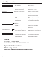
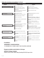
16
What to check Possible Cause Remedy
Faulty recoil starter.
Fluid in the crankcase.
Internal damage.
Consult with an authorized Shindaiwa
dealer.
Tighten and re-test.
Consult with an authorized Shindaiwa
dealer.
Re¿ ll with clean fresh unleaded gasoline
with a pump octane of 87 or higher, mixed
with a Premium 2-cycle Engine Oil at a
50:1 gasoline/oil ratio. Re-start.
Clean or replace ¿ lter/vent as required.
Re-start.
Consult with an authorized Shindaiwa
dealer.
Move switch to ON (“I”) and re-start.
Consult with an authorized Shindaiwa
dealer.
Crank the engine with the plug removed
and the ignition switch off. Replace the
plug, and re-start.
Clean and re-gap the plug to 0.6 - 0.7 mm.
Restart.
Replace the plug with a NGK BMR6A.
Re-start.
Loose spark plug.
Excess wear on cylinder, piston, rings.
Fuel is old or contaminated.
Clogged fuel ¿ lter and/or vent.
Carburetor primer failure.
The ignition switch is in OFF (“O”).
Faulty ignition ground.
Faulty transistor unit.
If the plug is wet, excess fuel may be in
the cylinder.
The plug may be fouled or improperly
gapped.
The plug may be damaged internally or
is the wrong size.
Does the engine crank?
Good compression?
Does the tank contain fresh
fuel of the proper grade?
Is fuel visible and moving in
the return line when priming?
Is there spark at the spark
plug wire terminal?
Check the spark plug.
Engine Does Not Start
Troubleshooting Guide
NO
NO
NO
NO
NO

17
What to check Possible Cause Remedy
Operator is overworking the unit.
Carburetor mixture is too lean.
Improper fuel/oil ratio.
Fan, fan cover, cylinder ¿ ns dirty or
damaged.
Carbon deposits on the piston or in
the mufÀ er.
Clogged air ¿ lter.
Loose or damaged spark plug.
Air leakage or clogged fuel line.
Fuel is old or contaminated.
Piston seizure.
Faulty carburetor and/or diaphragm.
Overheating condition.
Improper fuel.
Carbon deposits in the combustion
chamber.
Cut at a slower rate.
Consult with an authorized Shindaiwa
dealer.
Re¿ ll with clean fresh unleaded gasoline
with a pump octane of 87 or higher, mixed
with a Premium 2-cycle Engine Oil at a
50:1 gasoline/oil ratio.
Clean, repair or replace as necessary.
Consult with an authorized Shindaiwa
dealer.
Clean or replace the air ¿ lter.
Tighten or replace.
Repair or replace ¿ lter and/or fuel line.
Re¿ ll with clean fresh unleaded gasoline
with a pump octane of 87 or higher, mixed
with a Premium 2-cycle Engine Oil at a
50:1 gasoline/oil ratio.
Consult with an authorized Shindaiwa
dealer.
Consult with an authorized Shindaiwa
dealer.
See “Overheating” above.
Check fuel octane rating; check for
presence of alcohol in the fuel. Refuel as
necessary.
Consult with an authorized Shindaiwa
dealer.
Is the engine overheating?
Engine is rough at all speeds.
May also have black smoke
and/or unburned fuel at the
exhaust.
Engine is knocking.
Low Power output
Troubleshooting Guide (continued)

18
What to check Possible Cause Remedy
Clogged air ¿ lter.
Clogged fuel ¿ lter.
Carburetor mixture too lean.
Idle speed set too low.
Switch turned off.
Fuel tank empty.
Clogged fuel ¿ lter.
Water in the fuel.
Shorted spark plug or loose
terminal.
Ignition failure.
Piston seizure
Ground (stop) wire is disconnected,
or switch is defective.
Overheating due to incorrect spark
plug.
Overheated engine.
Engine idle too high.
Broken clutch spring or worn clutch
spring boss.
Warped or damaged guide bar or
cutters.
Damaged gearcase.
Shoulder bolts/cutters worn or out of
adjustment.
Manufacturer
YAMABIKO CORPORATION
7-2 SUEHIROCHO 1-CHOME, OHME, TOKYO 198-8760, JAPAN
Authorized Representative in Europe
Atlantic Bridge Limited
Atlantic House, PO Box 4800, Earley, Reading RG5 4GB, United Kingdom
Clean the air ¿ lter.
Replace the fuel ¿ lter.
Return trimmer to the dealer.
Adjust: 3000 min
-1
(rpm)
Reset the switch and re-start.
Refuel.
Replace ¿ lter.
Drain; replace with clean fuel. (See page 9).
Clean and replace spark plug, tighten the
terminal.
Replace the ignition unit.
Consult with an authorized Shindaiwa dealer.
Test and replace as required.
Clean and regap to 0.6 - 0.7 mm.
Correct plug: NGK BMR6A
Idle engine until cool
Set idle: 3000 min
-1
(rpm)
Replace spring/shoes as required, check idle
speed.
Inspect and replace as required.
Consult with an authorized Shindaiwa dealer.
Adjust or replace as required.
Poor acceleration.
Engine stops abruptly.
Engine dif¿ cult to shut off.
Cutting attachment rotates at
engine idle.
Excessive vibration.
Additional Problems
Troubleshooting Guide (continued)

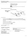
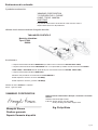
19
Declaration of Conformity
The undersigned manufacturer:
YAMABIKO CORPORATION
7-2 SUEHIROCHO 1-CHOME
OHME ; TOKYO 198-8760
JAPAN
This declaration of conformity is issued under the sole responsibility of
the manufacturer.
declares that the hereunder specifi ed new unit:
PORTABLE HEDGE TRIMMER
Brand: shindaiwa
Type: HT230
DH230
complies with:
* the requirements of Directive 2006/42/EC (use of harmonized standard EN ISO 10517: 2009)
* the requirements of Directive 2004/108/EC until 19th April 2016 (use of harmonized standard EN ISO 14982: 2009)
and 2014/30/EU from 20th April 2016 (use of harmonized standard EN ISO 14982: 2009)
* the requirements of Directive 2000/14/EC
Conformity assessment procedure followed ANNEX V
Measured sound power level : 105dB(A)
Guaranteed sound power level : 106dB(A)
Serial Number 36000001 and up
Tokyo, January 1st, 2016
Masayuki Kimura
General Manager
Quality Assurance Dept.
YAMABIKO CORPORATION
The authorized Representative in Europe
who is authorized to compile the technical fi le.
Company: Atlantic Bridge Limited
Address: Atlantic House, PO Box 4800,
Earley, Reading RG5 4GB, UK
Mr. Philip Wicks

GB
X750 286-270 4
7-2 SUEHIROCHO 1-CHOME, OHME, TOKIO 198-8760, JAPAN
PHONE: 81-428-32-6118. FAX: 81-428-32-6145.
© 2011
X750-0 27 15 0
Printed in Japan
La pagina si sta caricando...
La pagina si sta caricando...
La pagina si sta caricando...
La pagina si sta caricando...
La pagina si sta caricando...
La pagina si sta caricando...
La pagina si sta caricando...
La pagina si sta caricando...
La pagina si sta caricando...
La pagina si sta caricando...
La pagina si sta caricando...
La pagina si sta caricando...
La pagina si sta caricando...
La pagina si sta caricando...
La pagina si sta caricando...
La pagina si sta caricando...
La pagina si sta caricando...
La pagina si sta caricando...
La pagina si sta caricando...
La pagina si sta caricando...
La pagina si sta caricando...
La pagina si sta caricando...
La pagina si sta caricando...
La pagina si sta caricando...
La pagina si sta caricando...
La pagina si sta caricando...
La pagina si sta caricando...
La pagina si sta caricando...
La pagina si sta caricando...
La pagina si sta caricando...
La pagina si sta caricando...
La pagina si sta caricando...
La pagina si sta caricando...
La pagina si sta caricando...
La pagina si sta caricando...
La pagina si sta caricando...
La pagina si sta caricando...
La pagina si sta caricando...
La pagina si sta caricando...
La pagina si sta caricando...
-
 1
1
-
 2
2
-
 3
3
-
 4
4
-
 5
5
-
 6
6
-
 7
7
-
 8
8
-
 9
9
-
 10
10
-
 11
11
-
 12
12
-
 13
13
-
 14
14
-
 15
15
-
 16
16
-
 17
17
-
 18
18
-
 19
19
-
 20
20
-
 21
21
-
 22
22
-
 23
23
-
 24
24
-
 25
25
-
 26
26
-
 27
27
-
 28
28
-
 29
29
-
 30
30
-
 31
31
-
 32
32
-
 33
33
-
 34
34
-
 35
35
-
 36
36
-
 37
37
-
 38
38
-
 39
39
-
 40
40
-
 41
41
-
 42
42
-
 43
43
-
 44
44
-
 45
45
-
 46
46
-
 47
47
-
 48
48
-
 49
49
-
 50
50
-
 51
51
-
 52
52
-
 53
53
-
 54
54
-
 55
55
-
 56
56
-
 57
57
-
 58
58
-
 59
59
-
 60
60


Shindaiwa DH230-30 Manuale utente
- Categoria
- Tagliasiepi a motore
- Tipo
- Manuale utente
- Questo manuale è adatto anche per
in altre lingue
- English: Shindaiwa DH230-30 User manual
- français: Shindaiwa DH230-30 Manuel utilisateur
Documenti correlati
-
Shindaiwa HT2510_DH2510_DH2510T Manuale utente
-
-
-
-
-
-
-
-
-
Altri documenti
-
 Valex 1493204 Manuale del proprietario
-
Hitachi CH 78EC3 (ST) Manuale del proprietario
-
Dolmar HT-2460 Manuale del proprietario
-
Efco OM 98 L/14,5 K Manuale del proprietario
-
 GARDEO PRO GTHT26RH-BAG Manuale del proprietario
-
Hitachi CH78EC-C Manuale del proprietario
-
Hitachi CH 22EC2 (78ST) Manuale del proprietario
-
Makita HT-2556D Manuale utente
-
Hitachi CH22EC-78ST Manuale del proprietario

