ProLights 35W zoomable LED ellipsoidals Manuale utente
- Categoria
- Proiettori
- Tipo
- Manuale utente

USER MANUAL
MANUALE UTENTE
GALLERYECLTU
GALLERYECLDY
EN - IT
MINI LED ELLIPSOIDAL

All rights reserved by Music & Lights S.r.l. No part of this instruction manual may be
reproduced in any form or by any means for any commercial use.
In order to improve the quality of products, Music&Lights S.r.l. reserves the right to modify the
characteristics stated in this instruction manual at any time and without prior notice.
All revisions and updates are available in the ‘manuals’ section on site www.musiclights.it
REV.01-05/17

1
GALLERYECLTU - GALLERYECLDY
Packing content
• GALLERYECLTU-DY
• User manual
TABLE OF CONTENTS
Safety
General instructionsGeneral instructions
Warnings and installation precautionsWarnings and installation precautions
1 Introduction
1. 1 Operating elements and connections1. 1 Operating elements and connections
2 Installation
2. 1 Mounting2. 1 Mounting
3 Functions and settings
3. 1 Operation3. 1 Operation
3. 2 Basic3. 2 Basic
3. 3 Menu structure3. 3 Menu structure
3. 4 DMX mode3. 4 DMX mode
3. 5 DMX conguration3. 5 DMX conguration
3. 6 Wireless setting3. 6 Wireless setting
3. 7 Channels DMX3. 7 Channels DMX
3. 8 Display settings3. 8 Display settings
3. 9 Fixture settings3. 9 Fixture settings
3. 10 Fixture informations3. 10 Fixture informations
3. 11Operations in automatic mode3. 11Operations in automatic mode
4 Maintenance
4. 1 Maintenance and cleaning the unit4. 1 Maintenance and cleaning the unit
4. 2 Trouble shooting4. 2 Trouble shooting
2
2
3
4
5
6
6
7
8
8
8
9
10
10
10
11
12
12

GALLERYECLTU - GALLERYECLDY
2
SAFETY
General instruction
• The products referred to in this manual conform to the European Community Directives and are there-
fore marked with .
• The unit is supplied with hazardous network voltage (230V~). Leave servicing to skilled personnel only.
Never make any modications on the unit not described in this instruction manual, otherwise you will
risk an electric shock.
• Connection must be made to a power supply system tted with ecient earthing (Class I appliance ac-
cording to standard EN 60598-1). It is, moreover, recommended to protect the supply lines of the units
from indirect contact and/or shorting to earth by using appropriately sized residual current devices.
• The connection to the main network of electric distribution must be carried out by a qualied electrical
installer. Check that the main frequency and voltage correspond to those for which the unit is designed
as given on the electrical data label.
• This unit is not for home use, only professional applications.
• Never use the xture under the following conditions:
- in places subject to vibrations or bumps;
- in places with a temperature of over 45 °C.
• Make certain that no inammable liquids, water or metal objects enter the xture.
• Do not dismantle or modify the xture.
• All work must always be carried out by qualied technical personnel. Contact the nearest sales point for
an inspection or contact the manufacturer directly.
• If the unit is to be put out of operation denitively, take it to a local recycling
plant for a disposal which is not harmful to the environment.
Warnings and installation precautions
• If this device will be operated in any way dierent to the one described in this manual, it may suer
damage and the guarantee becomes void. Furthermore, any other operation may lead to dangers like
short circuit, burns, electric shock, etc.
• Before starting any maintenance work or cleaning the projector, cut o power from the main supply.
• Always additionally secure the projector with the safety rope. When carrying out any work, always com-
ply scrupulously with all the regulations (particularly regarding safety) currently in force in the country
in which the xture’s being used.
• Install the xture in a well ventilated place.
• Keep any inammable material at a safe distance from the xture.
• Shields, lenses or ultraviolet screens shall be changed if they have become damaged to such an extent
that their eectiveness is impaired.
• The lamp (LED) shall be changed if it has become damaged or thermally deformed.
• Never look directly at the light beam. Please note that fast changes in lighting, e. g. ashing light, may
trigger epileptic seizures in photosensitive persons or persons with epilepsy.
• Do not touch the product’s housing when operating because it may be very hot.
• This product was designed and built strictly for the use indicated in this documentation. Any other use,
not expressly indicated here, could compromise the good condition/operation of the product and/or
be a source of danger.
• We decline any liability deriving from improper use of the product
WARNING! Before carrying out any operations with the unit, carefully read this instruction
manual and keep it with cure for future reference. It contains important information about
the installation, usage and maintenance of the unit.

3
GALLERYECLTU - GALLERYECLDY
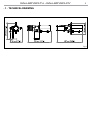
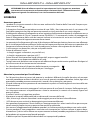
- 1 - TECHNICAL DRAWING
Fig.1

GALLERYECLTU-DY
44
5
5
7
11
9
8
2
3
6
Fig.2
GALLERYECLTU - GALLERYECLDY
4
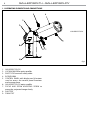
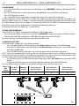
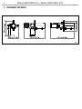
1.1 OPERATING ELEMENTS AND CONNECTIONS
1. GALLERYECLTU-DY
2. LOCKING KNOB for optics proler
3. SAFETY EYE to attach safety cable.
4. ROTARY ARM
5. CONTROL PANEL with display and 4 buttons
used to access the control panel functions
and manage them
6. GALLERYECLTU-DY optics proler
7. FOCUS AND ZOOM ADJUSTING SCREW to
zoom the projected image clearly
8. SHUTTER
9. FIXING TILT

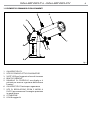
Fig.4
1
2
3
5
GALLERYECLTU - GALLERYECLDY
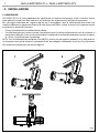
- 2 - INSTALLATION
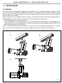
2.1 MOUNTING
GALLERYECLTU-DY is designed for applications in exhibition areas, commercial spaces, museums, restau-
rant, churches, and any other installation where size is an important factor. For xing, stable mounting
clips are required. The mounting place must be of sucient stability and be able to support a weight of
10 times of the unit’s weight.
When carrying out any installation, always comply scrupulously with all the regulations (particularly re-
garding safety) currently in force in the country in which the xture’s being used.
• Install the projector at a suitable location.
• Always additionally secure the projector with the safety rope from falling down. For this purpose, fas-
ten the safety rope at a suitable position so that the maximum fall of the projector will be 20 cm. The
adjust the projector and use the knobs.
NOTE - For the installation of the GALLERYECLDY make sure that the ridge of the adaptor is in with the
groove of the track. Turn knobs 90° to connect the adaptor to the circuit. Please see the gure 4.

CONNECT SETUP ADVANCED INFORMATION STAND ALONE
GALLERYECLTU - GALLERYECLDY
6
- 3 - FUNCTIONS AND SETTINGS
3.1 OPERATION
To turn on the GALLERYECLTU-DY connect the supplied main cable to a socket (100-240 VAC-50/60 Hz).
Then the unit is ready for operation. You can also adjust the dimmer and zoom using the knobs.
To switch o, disconnect the mains plug from the socket. For a more convenient operation it is recom-
mended to connect the unit to a socket which can be switched on and o via a light switch.
NOTE - To operate the projector GALLERYECL you need a system track. The track system must be installed
and maintained by a suitably qualied person in compliance with latest construction and relevant legisla-
tion. It is the responsibility of the installer to ensure the electrical, mechanical and thermal compatibility
of the track system and the ttings. The connection to the main network of electric distribution must be
carried out by a qualied electrical installer.
ATTENTION - Mains voltage must be switched o before mounting; maintenance; insert and replace
Adaptors; spots and luminaires.
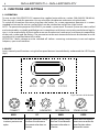
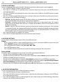
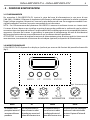
3.2 BASIC
Access control panel functions using the four panel buttons located directly underneath the LED Display
(g.5).
MENU UP DOWN ENTER
Used to access the menu or
to return a previous menu
option
Navigates downwards through
the menu list and increases
the numeric value when in a
function
Navigates upwards through
the menu list and decreases
the numeric value when in
a function
Used to select and store the
current menu or conrm the
current function value or
option within a menu
MENU UP DOWN ENTER
Fig.5- Functions of the buttons

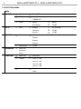
MENU
1 CONNECT
ð
Address
ð
Value (1-512)
ð
DMX Mode
ð
Basic 1CH
STANDARD 3CH
ð
Wireless
ð
Receive
ð
ON/OFF
Reset Connect
ð
YES/NO
2 SET UP
ð
Screen
ð
Backlight
ð
On (10s,20s,30s)
Flip Display
ð
YES/NO
Key Lock
ð
YES/NO
3 ADVANCED
ð
Dimmer Mode
ð
o
Dimmer 1
Dimmer 2
Dimmer 3
ð
Factory Reload
ð
YES/NO
4 INFORMATION
ð
Fixture Time
Temperature
Version
5 STAND ALONE
ð
Master/Slave
ð
Master/Slave
ð
Sequence
ð
Show 1 (1~100)
Show 2 (1~100)
Show 3 (1~100)
Show 4 (1~100)
ð
Static
ð
Dimmer
Strobe
7
GALLERYECLTU - GALLERYECLDY
3.3 MENU STRUCTURE

GALLERYECLTU - GALLERYECLDY
8
3.4 DMX MODE
• Press the button MENU so many times until the display shows DMX ADDRESS, and press the button ENTER
to conrm.
• Press UP/DOWN button to select the desired value (001-512). Press and hold to scroll quickly.
• Press ENTER button to store.
• Press the MENU button to go back or to meet the waiting time to exit the setup menu.
To able to operate the GALLERYECLTU-DY/TRWD with a light controller, adjust the DMX start address for
the rst a DMX channel. If e. g. address 33 on the controller is provided for controlling the function of the
rst DMX channel, adjust the start address 33 on the GALLERYECLTU-DY/TRWD. The other functions of the
light eect panel are then automatically assigned to the following addresses.
An example with the start address 33 is shown below:
3.5 DMX CONFIGURATION
GALLERYECLTU-DY/TRWD is equipped with dierent DMX conguration.
• Press the button MENU so many times until shows DMX CHANNEL, and press the button ENTER to conrm.
• Select the desired DMX conguration (1CH - 3CH ) through the buttons UP/DOWN.
The tables on page 16 indicate the operating mode and DMX value.
3.6 WIRELESS SETTING
To set the wireless mode refer to the following guide:
• Press the MENU button until the display shows Wireless Setting, then press the ENTER button.
• Use the UP/DOWN button until the display reads Wireless Receive, and then press the ENTER button
and select the ON mode.
• Press the MENU button to go back or to meet the waiting time to exit the setup menu.
NOTE - After you complete these steps, you have to synchronize with any wi unit with which you want
to communicate by pressing the sync button present on the same. Then connect any DMX console to wi
unit for to open the communication with the GALLERYECLTU-DY/TRWD unit.
• To reset the unit press the MENU button until the display shows Reset Connect, then press the ENTER
button.
• Use the UP/DOWN button until the display reads Yes, and then press the ENTER button.
Press the MENU button to go back or to meet the waiting time to exit the setup menu.
Number of
DMX
channels
Start address
(example)
DMX Address
occupied
Next possible start
address for unit No. 1
Next possible start
address for unit No. 2
Next possible start
address for unit No. 3
3 33 33-35 36 39 42
Fig.6
DMX512 Controller
wireless
solution

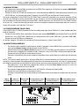
3 CANALI
MODE
FUNCTION DMX
Value
3 Ch
1
DIMMER
0~100% 000 - 255
2
SHUTTER
No function (shutter open)
Strobe eect slow to fast
No function (shutter open)
Pulse-eect in sequences(slow to fast)
No function (shutter open)
Random strobe eect slow to fast
No function (shutter open)
000 - 010
011 - 082
083 - 093
094 - 163
164 - 174
175 - 244
245 - 255
3
DIMMER FADE
Preset dimmer speed from display menu
Dimmer snap to fade
000 - 000
001 - 255
1 CANALE
MODE
FUNCTION DMX
Value
1 Ch
1
DIMMER
0~100% 000 - 255
9
GALLERYECLTU - GALLERYECLDY
3.7 CHANNELS DMX

GALLERYECLTU - GALLERYECLDY
10
3.8 DISPLAY SETTINGS
You can change the following parameters related to the display, following the same procedure:
• Press the ENTER button to access the main menu.
• Press the UP / DOWN keys to scroll the menu, select the Setup icon, then press the ENTER button to
enter the next menu.
• Press UP / DOWN to scroll through the menu, then select UI Set, and press the ENTER button to enter
the next menu.
• Press UP / DOWN to scroll through the menu, and then select one of the following settings for the dis-
play and press the ENTER key to display it.
- Back Light - Backlight display Auto O. This feature allows you to automatically turn o the backlight
after a specied time that you can set using the arrow buttons.
- Flip Display - Orientation of the display. This function allows you to rotate the display 180° to get a
better view of the display when the unit is hanging upside down. Select YES to activate or NO to
disable this function.
- Key Lock - Lock keys. With this function, you can lock the buttons on the control panel. If this function
is activated, the keys are automatically locked. To disable or temporarily disable the key lock func-
tion, press the buttons in the following order to regain access to menu commands: UP, DOWN, LEFT,
RIGHT, ENTER. Select YES to activate or NO to disable.
• Press the ENTER button to conrm your choice.
• Press the LEFT button repeatedly to exit the menu and save changes.
3.9 FIXTURE SETTINGS
It is possible to change the parameter value in the following way:
Dimmer
• Enter in Dimmer mode to select specic dimming curve, press the button MENU so many times until
shows DIM MODE, and press the button ENTER to conrm.
• Press the button UP/DOWN to select OFF - DIM1 - DIM2 - DIM3.
• Press ENTER button to store.
• Press the MENU button to go back or to meet the waiting time to exit the setup menu.
Factory Reload
Selezionare questa funzione per ripristinare l’unità alle impostazioni di fabbrica:
• Premere il tasto ENTER per accedere al menu principale.
• Premere il tasto UP/DOWN per scorrere nel menu, selezionare l’icona Advanced, quindi premere il tasto
ENTER per accedere al menu successivo.
• Premere il tasto UP/DOWN per selezionare Reload Default e premere il tasto ENTER per procedere.
• Premere il tasto UP/DOWN per selezionare la modalità di ripristino preferita Basic Reload/Program Reload/
Private Reload/All Reload, quindi premere il tasto ENTER per confermare.
• Premere i tasti UP/DOWN per selezionare YES oppure NO, quindi premere il tasto ENTER per confermare.
3.10 FIXTURE INFORMATION
To view all the information on the device, proceed as follows:
• Press the ENTER button to access the main menu.
• Press the UP/DOWN button to scroll the menu, select the icon Information, then press the ENTER but-
ton to enter the next menu.
• Press the UP/DOWN button to scroll through the menu, then select one of the following information
and press the ENTER button to display it.

11
GALLERYECLTU - GALLERYECLDY
- Fixture Time - Through the Fixture Time function you can display the operating time of the projector.
- Temperature - Through the Temperature function can be displayed the temperature inside the x-
ture, near the lamp. The temperature can be displayed in degrees Celsius or Fahrenheit.
- Version - Through Version function you can display the currently installed software version.
• Press the LEFT button repeatedly to exit the menu.
3.11 OPERATIONS IN AUTOMATIC MODE
The unit independently runs through its show. Before you send an automatic program you need to set the
drive as Master/Alone:
• Press the ENTER button to access the main menu.
• Press the UP/DOWN button to scroll the menu, select the Stand Alone icon, then press the ENTER button
to enter the next menu.
Press the UP/DOWN button to scroll through the menu, select Master/Slave and press ENTER to conrm your
choice.
• Press the UP/DOWN button to select the mode of operation:
- Master, if the unit is connected in series with other units and it acts as the Master;
- Slave, if the unit is not connected to other units.
• Press the ENTER button to conrm your choice.
Press the UP/DOWN button to scroll through the menu, select Sequence and press ENTER to conrm your
choice.
• Press the UP/DOWN button to select the mode of operation: Show 1, Show 2, Show 3, Show 4
• Press the ENTER button to conrm your choice.
• Press the LEFT button repeatedly to exit the menu and save changes.
The unit will go into automatic mode by executing the program automatically.

GALLERYECLTU - GALLERYECLDY
12
- 4 - MAINTENANCE
4.1 MAINTENANCE AND CLEANING THE UNIT
• Make sure the area below the installation place is free from unwanted persons during setup.
• Switch o the unit, unplug the main cable and wait until the unit has cooled down.
• All screws used for installing the device and any of its parts should be tightly fastened and should not
be corroded.
• Housings, xations and installation spots (ceiling, trusses, suspensions) should be totally free from any
deformation.
• The main cables must be in impeccable condition and should be replaced immediately even when a
small problem is detected.
• It is recommended to clean the front at regular intervals, from impurities caused by dust, smoke, or
other particles to ensure that the light is radiated at maximum brightness. For cleaning, disconnect the
main plug from the socket. Use a soft, clean cloth moistened with a mild detergent. Then carefully wipe
the part dry. For cleaning other housing parts use only a soft, clean cloth. Never use a liquid, it might
penetrate the unit and cause damage to it.
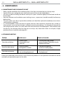
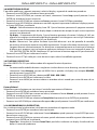
4.2 TROUBLESHOOTING
Problems Possible causes Checks and remedies
Fixture does not light up
• No mains supply
• Dimmer fader set to 0
• Faulty LED
• Check the power supply voltage
• Increase the value of the dimmer channels
• Replace the LED board
General low light intensity
• Dirty lens assembly
• Misaligned lens assembly
• Clean the xture regularly
• Install lens assembly properly
Fixture does not power up
• No power
• Loose or damaged power cord
• Check for power on power outlet
• Check power cord
Contact an authorized service center in case of technical problems or not reported in the table can not be
resolved by the procedure given in the table.

REV.01-05/17
Music & Lights S.r.l. si riserva ogni diritto di elaborazione in qualsiasi forma delle presenti istruzioni per l’uso.
La riproduzione - anche parziale - per propri scopi commerciali è vietata.
Al ne di migliorare la qualità dei prodotti, la Music&Lights S.r.l. si riserva la facoltà di modicare, in
qualunque momento e senza preavviso, le speciche menzionate nel presente manuale di istruzioni.
Tutte le revisioni e gli aggiornamenti sono disponibili nella sezione 'Manuali' sul sito www.musiclights.it

GALLERYECLTU - GALLERYECLDY
3
• GALLERYECLTU-DY
• Manuale utente
Contenuto dell'imballo:
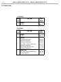
INDICE
Sicurezza
Avvertenze generaliAvvertenze generali
Attenzioni e precauzioni per l’installazioneAttenzioni e precauzioni per l’installazione
1 Disegno tecnico
1. 1 Elementi di comando e di collegamento 1. 1 Elementi di comando e di collegamento
2 Installazione
2. 1 Montaggio2. 1 Montaggio
3 Funzioni e impostazioni
3. 1 Funzionamento3. 1 Funzionamento
3. 2 Impostazione base3. 2 Impostazione base
3. 3 Struttura menù3. 3 Struttura menù
3. 4 Modalità Autoshow3. 4 Modalità Autoshow
3. 5 Modalità Static3. 5 Modalità Static
3. 6 Congurazione canali3. 6 Congurazione canali
3. 7 Modalità DMX3. 7 Modalità DMX
3. 8 Canali DMX3. 8 Canali DMX
3. 9 Funzioni dispositivo3. 9 Funzioni dispositivo
3. 10 Informazioni sul dispositivo3. 10 Informazioni sul dispositivo
3. 11Impostazioni Wireless3. 11Impostazioni Wireless
4 Manutenzione
4. 1 Manutenzione e pulizia del sistema ottico4. 1 Manutenzione e pulizia del sistema ottico
4. 2 Risoluzione dei problemi4. 2 Risoluzione dei problemi
4
4
5
6
7
8
8
9
10
10
10
11
12
12
12
13
14
14

4
GALLERYECLTU - GALLERYECLDY
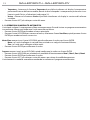
ATTENZIONE! Prima di effettuare qualsiasi operazione con l’unità, leggere con attenzione
questo manuale e conservarlo accuratamente per riferimenti futuri. Contiene informazioni
importanti riguardo l’installazione, l’uso e la manutenzione dell’unità.
SICUREZZA
Avvertenze generali
• I prodotti a cui questo manuale si riferisce sono conformi alle Direttive della Comunità Europea e per-
tanto recano la sigla .
• Il dispositivo funziona con pericolosa tensione di rete 230V~. Non intervenire mai al suo interno al di
fuori delle operazioni descritte nel presente manuale; esiste il pericolo di una scarica elettrica.
• È obbligatorio eettuare il collegamento ad un impianto di alimentazione dotato di un’eciente messa
a terra (apparecchio di Classe I secondo norma EN 60598-1). Si raccomanda, inoltre, di proteggere le
linee di alimentazione delle unità dai contatti indiretti e/o cortocircuiti verso massa tramite l’uso di
interruttori dierenziali opportunamente dimensionati.
• Le operazioni di collegamento alla rete di distribuzione dell’energia elettrica devono essere eettuate
da un installatore elettrico qualicato. Vericare che frequenza e tensione della rete corrispondono alla
frequenza ed alla tensione per cui l’unità è predisposta, indicate sulla targhetta dei dati elettrici.
• L’unità non per uso domestico, solo per uso professionale.
• Evitare di utilizzare l’unità:
- in luoghi soggetti a vibrazioni, o a possibili urti;
- in luoghi a temperatura superiore ai 45°C.
• Evitare che nell’unità penetrino liquidi inammabili, acqua o oggetti metallici.
• Non smontare e non apportare modiche all’unità.
• Tutti gli interventi devono essere sempre e solo eettuati da personale tecnico qualicato. Rivolgersi al
più vicino centro di assistenza tecnica autorizzato.
• Se si desidera eliminare il dispositivo denitivamente, consegnarlo
per lo smaltimento ad un’istituzione locale per il riciclaggio.
Attenzioni e precauzioni per l’installazione
• Se il dispositivo dovesse trovarsi ad operare in condizioni dierenti da quelle descritte nel presente
manuale, potrebbero vericarsi dei danni; in tal caso la garanzia verrebbe a decadere. Inoltre, ogni altra
operazione potrebbe provocare cortocircuiti, incendi, scosse elettriche, rotture etc.
• Prima di iniziare qualsiasi operazione di manutenzione o pulizia sull’unità togliere la tensione dalla rete
di alimentazione.
• È assolutamente necessario proteggere l’unità per mezzo di una fune di sicurezza. Nell’eseguire qual-
siasi intervento attenersi scrupolosamente a tutte le normative (in materia di sicurezza) vigenti nel
paese di utilizzo.
• Installare l’unità in un luogo ben ventilato.
• Mantenere i materiali inammabili ad una distanza di sicurezza dall’unità.
• I ltri, le lenti o gli schermi ultravioletti se danneggiati possono limitare la loro ecienza.
• I LED devono essere sostituiti se danneggiati o termicamente deformati.
• Non guardare direttamente il fascio luminoso. Tenete presente che i veloci cambi di luce possono pro-
vocare attacchi d’epilessia presso persone fotosensibili o epilettiche.
• Non toccare l’alloggiamento del prodotto quando è in funzione perché potrebbe essere molto caldo.
• Questo prodotto è stato progettato e costruito esclusivamente per l’utilizzo indicato in questa docu-
mentazione. Qualsiasi altro utilizzo non espressamente indicato potrebbe pregiudicare la funzionalità
del prodotto e/o rappresentare fonte di pericolo.
• Si declina qualsiasi responsabilità derivata dall’uso improprio del prodotto.

GALLERYECLTU - GALLERYECLDY
5
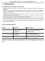
- 1 - DISEGNO TECNICO
Fig.1

Fig.3
1. GALLERYECLTU-DY
2. VITE DI FISSAGGIO OTTICA SAGOMATORE
3. SAFETY EYE per l’aggancio al cavo di sicurezza
4. BRACCIO GIREVOLE
5. PANNELLO DI CONTROLLO con display e 4
pulsanti per accesso e gestione delle diverse
funzioni.
6. GALLERYECLTU-DY ottica per sagomatore
7. VITE DI REGOLAZIONE ZOOM E MESSA A
FUOCO per zoommare l'immagine proiettata
in modo chiaro
8. OTTURATORE
9. LEVA ssaggio tilt
44
5
5
7
11
9
8
2
3
6
1.1 ELEMENTI DI COMANDO E COLLEGAMENTI
6
GALLERYECLTU - GALLERYECLDY

Fig.4
GALLERYECLTU - GALLERYECLDY
7
- 2 - INSTALLAZIONE
2.1 MONTAGGIO
GALLERYECLTU-DY è stato progettato per applicazioni in campo commerciale, musei, ristoranti, chiese,
teatri educativi e qualsiasi altro ambito in cui le dimensioni rappresentano un fattore importante.
Per il ssaggio occorrono dei supporti robusti per il montaggio. L’area di collocazione deve avere una
stabilità suciente e supportare almeno 10 volte il peso dell’unità. Inoltre assicurarsi di rispettare tutte le
avvertenze in materia di sicurezza.
• Fissare il proiettore ad una collocazione idonea.
• È assolutamente necessario assicurare il proiettore contro la caduta utilizzando un cavo di sicurezza: in
particolare collegare il cavo in un punto adatto in modo che la caduta del proiettore non possa supera-
re i 20 cm. Quindi orientare il proiettore.
NOTA - Per l’installazione del proiettore GALLERYECL inserire il track adapter (optional) in un idoneo bina-
rio a quattro linee quindi ruotare la manopola di 90° per collegare l’adattatore al circuito. Far riferimento
alla sequenza di operazioni mostrate in gura 4.
1
2
3
La pagina si sta caricando...
La pagina si sta caricando...
La pagina si sta caricando...
La pagina si sta caricando...
La pagina si sta caricando...
La pagina si sta caricando...
La pagina si sta caricando...
La pagina si sta caricando...
-
 1
1
-
 2
2
-
 3
3
-
 4
4
-
 5
5
-
 6
6
-
 7
7
-
 8
8
-
 9
9
-
 10
10
-
 11
11
-
 12
12
-
 13
13
-
 14
14
-
 15
15
-
 16
16
-
 17
17
-
 18
18
-
 19
19
-
 20
20
-
 21
21
-
 22
22
-
 23
23
-
 24
24
-
 25
25
-
 26
26
-
 27
27
-
 28
28


ProLights 35W zoomable LED ellipsoidals Manuale utente
- Categoria
- Proiettori
- Tipo
- Manuale utente
in altre lingue
Documenti correlati
-
ProLights 60 W RGBW / FC zoomable LED ellipsoidals Manuale utente
-
-
-
-
ProLights LED Fresnel Manuale utente
-
-
-
-
-