Jamara FCX6 Pro Tel Istruzioni per l'uso
- Categoria
- Giocattoli telecomandati
- Tipo
- Istruzioni per l'uso

IT - Istruzioni di montaggio
GB - Instruction
FCX6 Pro Tel
Trasmittente | Transmitter
No. 061260 Gas sinistra
IT - Informazioni generali
Jamara e. K. non e´responsabile per dan-
ni, sostenute al prodotto stesso o attraver-
so questo, dovuti ad una gestione non cor-
retta del articolo. Solo il cliente si assume
la piena responsabilità per la manutenzio-
ne e l´utilizzo corretto dello stesso; questo
include il montaggio, la ricarica, l´utilizzo,
no alla scelta della aerea di applicazione.
Si prega di notare e rispettare le istruzioni
d´uso, questi contengono informazioni e
avvertimenti molto importanti.
GB - General information
Jamara e.K. is not liable for any damage
caused to the product itself or by it, if this
is due to improper operation or handling
errors. The customer alone bears the full
responsibility for the proper use and hand-
ling, including in particular, assembling,
charging and using the model, and selec-
ting the area in which to use it. Please re-
fer to the operating and user instructions,
which contain important information and
warnings.
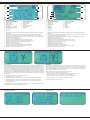
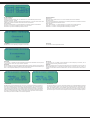
IT - Contenuto del kit:
• Trasmittente 2,4Ghz con 6 canali
• Ricevente 2,4Ghz con 6 canali
• Jumper (cavo ponte binding)
• Istruzione
GB - Box contents:
• 6 channel 2,4 GHz Transmitter
• 6 Channel 2,4 GHZ Receiver AFHDS 2A
• Link plug (binding pin)
• Manual
IT - Accessori consigliati:
Ricevente FCX 6 Pro Tel 2,4 GHz Sensor No. 06 1263
Sensore tensione No. 06 1265
Sensore velocita ottico No. 06 1266
Sensore velocita magnetico No. 06 1267
Sensore temperatura No. 06 1268
Cavo adattatore per simulatore No. 06 5017
GB - Recommended Accessories
Receiver FCX 6 Pro Tel 2,4 GHz Sensor No. 06 1263
Sensor Voltage No. 06 1265
Sensor rpm optical No. 06 1266
Sensor rpm magnetic No. 06 1267
Sensor Temperature No. 06 1268
Adapter cable for flight simulator No. 06 5017
IT - Highlights
• 2,4 GHz AFHDS 2A Digital Proprtional Radio Control System
• AFHDS 2A / AFHDS On-/OFF, possibile utilizzare la ricevente del modello precedente!!
• Regolazione di tensione della radio (Low V, Alarm, High V)
• Fail Safe in AFHDS 2A Modalità del canale 1 - 6 regolabile
• 6 canali
• 4 interruttori liberamente programmabili
• 2 potenziometri rotativi liberamente programmabili
• Display ampio digitale
• Acro, menu heli
• Memoria per 20 modelli
• Servo-inversione
• Delta
• Coda a V
• Dual Rate
• Expo
• Copia dei modelli
• Modalità maestro/allievo
• 170 x 95 x 190 mm
• 407,2 g
Dati tecnici ricevente FCX 6 Pro Tel 2,4 GHz
Frequenza 2,4 GHz
Modulazione AFHDS 2A
Modulazione servo 10 Bit (1024 Passi)
Tensione di operazione 4 - 6,5 V DC
Misure ~ 48 x 26 x 15 mm
Peso ~ 16,6 g
GB - Features:
• 2.4GHz AFHDS 2A Digital proprtional Radio Control System
• AFHDS 2A / AFHDS can be switched on / o, thus, using the receivers of the previous
model possible
• Adjustment of transmitter voltage (low V, Alarm, High V)
• Fail Safe can be set in channel 1 – 6 in AFHDS 2A Mode
• 6 channel
• 4 programmable Switches
• 2 programmable Poti
• Display
• Acrobatics, Heli menu
• 20 Model Memory
• Servo-Reverse
• Delta
• V-Tail
• Dualrate
• Expo
• Copy existing models
• Trainer/Simulator socket
• 170 x 95 x 190 mm
• 407,2 g
Technical data Receiver FCX 6 Pro Tel 2,4 GHz
Frequency 2,4 GHz
Modulation AFHDS 2A
Servo resolution 10 Bit (1024 Schritte)
Operating voltage 4 - 6,5 V DC
Size ~ 48 x 26 x 15 mm
Weight ~ 16,6 g
12/21
Frequency bands: 2.4Ghz Frequency range: 2408 – 2475 Mhz EIRP: < 40 mW (max. power transmitted)
IT - Dichiarazione di conformità
Con la presente JAMARA e.K. dichiara che il prodotto “FCX6 Pro Tel, No. 061260“ è
conforme alla Direttiva 2014/53/UE, 2011/65/UE.
Il testo integrale della dichiarazione di conformità UE è disponibile al seguente indiriz-
zo Internet: www.jamara-shop.com/Conformity
GB - Certicate of Conformity
Hereby JAMARA e.K. declares that the product “FCX6 Pro Tel, No. 061260“ complies with Directive
2014/53/EU, 2011/65/EU.
The full text of the EU Declaration of Conformity is available at the following Internet address:
www.jamara-shop.com/Conformity
IT - Questo modello non é un giocattolo!
Prima di avviare il modello, leggere attentamente tutte le istruzioni per l’uso.
Attenzione! Leggere completamente le avvertenze / istruzioni di sicurezza,
questi sono per la vostra sicurezza può prevenire incidenti / infortuni.
GB - For model building only - Not a toy!
Read the complete instructions and security instructions carefully before using the
model.
Caution! Please fully and carefully read warnings/ safety instructions.
These are for our own security and can avoid accidents/injuries.

2
IT - Sistema 2,4 GHz
AFHDS signica „Automatic Frequency Hopping Digital System“. Questo so sticato sistema di
trasmissione senza li si basa su anni di esperienza e vi garantisce una lunga autonomia e la lunga
durata della batteria. Questo è il risultato di anni di ricerca e sperimentazione. ed e´questo che fa di
Jamara una delle aziende leader a livello mondiale nel mercato.
Attenzione:
Si prega di leggere attentamente le istruzioni e di utilizzare il sistema radio esattamente come de-
scritto. Uso improprio e non corretto di questo sistema radio può causare lesioni gravi o addirittura
lesioni mortali. Questa frequenza da 2,4 GHz ha un comportamento completamente diverso da
quelli precedentemente utilizzati. Tenere sempre il vostro modello in vista, evitare oggetti di grandi
dimensioni che possono bloccare il segnale HF, questo porta il rischio di perdere il controllo e la
perdita del modello. Il 2,4-GHz segnale RF si propaga in linea retta e non può cercare una via in-
torno ai oggetti o addirittura passarli. Mai toccare l‘antenna trasmittentedurante il funzionamento di
un modello, questo può alterare in maniera signi cativa la qualità e la forza del segnale RF e può
causare pericoli che possano portare alla perdita di controllo.
Attenzione:
All‘avvio sempre accendere prima la trasmittente e poi la ricevente. Quando si spegne il sistema
sempre spegnere prima la ricevente poi la trasmittente. Questo consentirà di evitare che la riceven-
te riceve un segnale sbagliato, il quale potrebbe portare a mvimenti del servo irregolari. Questo è
particolarmente importante per il funzionamento di un modello, cosi che il motore non può partire
inaspettatamente, e quindi non può provocare lesioni che nel peggiore dei casi possano provocare
anche la morte.
GB - 2,4 GHz System
AFHDS2A stands for „Automatic Frequency Hopping Digital System 2A“. This highly sophistica-
ted radio transmission system will guarantee you a long range, jamming free and long battery life
experience. This is the result of years of research and testing and makes Jamara one of the word
leader in the market.
Danger
Misuse of this radio system can lead to serious injuries or death. Please read completely this ma-
nual and only operate your radio system according to it. The 2,4 GHz radio band has a comletely
dierent behavior than previously used lower frequency bands. Keep always your model in sight as
a large object can block the RF signal and lead to loss of control and danger. The 2,4 GHz RF signal
propagates in straight lines and cannot get around objects on its path. Never grip the transmitter
antenna when operating a model as it degrades signicantly the RF signal quality and strength and
may cause loss of control and danger.
Danger
Always turn on the transmitter rst then the receiver. When turning o the system, always turn o
the receiver rst than the transmitter. This is to avoid having the receiver on itself as it may pick a
wrong signal and lead to erratic servo movements. This is particularly important for electric powered
models as it may unexpectedly turn on the motor and lead to injuries or death.
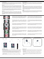
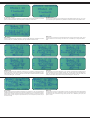
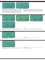
Antenna Dual
Per raggiungere delle distanze massime di sicurezza tra trasmittente e ricevente, si prega di seguire
le istruzioni riportati di seguito:
1. Le due antenne devono essere tenuti il più diritto possibile. Altrimenti la portata viene ridotta.
2. Le due antenne devono essere disposti a 90° fra loro, come si può vedere sulle tre immagini.
3. Le antenne devono essere tenuti lontani di materiali conduttivi come metallo o bra di carbonio
(per i modelli con fusoliera in bra di carbonio, portare l’antenna all’esterno). Per un
funzionamento sicuro é necessario una distanza minima di 1,5 cm. Materiali conduttivi hanno
meno impatto sulle parte coassiale dell’antenna ma é importante che non si piega la parte
coassiale a forti raggi.
4. Mantenre l‘antenna il più lontano possibile dal motore, regolatore é altre fonti di interferenza
Dual antenna notes
In order to make sure maximum distance between the transmitter and receiver please follow the
directions below:
1. The two antennas must be kept as straight as possible. Otherwise, control range will be reduced.
2. The two antennas should be placed at a 90 degree angle to each other, as illustrated in the tree
pictures below.
3. The antennas must be kept away from conductive materials, such as metal and carbon. A
distance of at least 1,5 cm is required for safe operating. Conductive materials will not aect the
coaxial part of the antenna, but it is important that the coaxials are not bend to a severe radius.
4. Keep antennas away from the motor, speed controller and other noise soures as much as
possible.
Caratteristica del sistema
Questo sistema radio opera nella banda di frequenza di 2,4 a 2,4835 GHz.
Questa banda è suddivisa in 160 canali indipendenti. Ogni sistema radio
utilizza 16 diversi canali e 160 diversi tipi di Hopping-Algorythmen. Usan-
do tempi di attivazione diversi, saltellando regime e frequenze dei canali, il
sistema in grado di garantire una trasmissione priva di errori radio.
Questo sistema wireless utilizza un alto fattore di ampli cazione e
l’elevata qualità dell´antenna multi - direzionale. Esso copre l‘intera banda
di frequenza. Collegato ad una ricevente con alta sensibilità, questo sis-
tema wireless garantisce una trasmissione radio a lunga distanza privo
di errori.
Ogni trasmittente ha un ID inequivocabile. Durante il binding con una ri-
cevente, la ricevente memorizza l‘ID, e può solo elaborare i dati di questo
trasmittente. Questo evita la raccolta di altri segnali di trasmissione e au-
menta notevolmente l‘immunità e la sicurezza.
Il sistema radio utilizza componenti a basso consumo e un chip ricevente
molto sensibile. La modulazione HF utilizza un sistema di trasmissione a
intermodulazione con la quale vengono evitati elevati consumi. In questo
sistema radio, è necessario solo un decimo della potenza, rispetto al con-
sumo di un sistema standard FM.
Sistema AFHDS 2A é una funzione di riconoscimento automatico, in grado
di passare automaticamente dalla modalità attuale é modalità di comuni-
cazione con funzione di ritorno dei dati é consente di applicare meglio il
stato di lavoro attuale per avere più divertimento.
AFHDS 2A verfügt über eine integrierte Mehrkanalcodierung und Fehler-
korrektur, um die Stabilität der Kommunikation zu verbessern, die Fehler-
quote zu reduzieren und um mehr Reichweite einer zuverlässigen Über-
tragung zu erreichen.
System Characteristic
This radio systems works in the frequency range of 2.4000 to 2.4835 GHz.
Thins band has been divided into 160 independent channels. Each radio
system uses 16 dierent channels and 160 dierent types of hopping al-
gorithm. By using various switch-on times, hopping scheme and channel
frequencies, the system can guarantee a jamming free radio transmission.
This radio system uses a high gain and high quality multidirectional anten-
na. It covers the whole frequency band. Associated with a high sensitivity
receiver, this radio system guarantees a jamming free long range radio
transmission.
Each transmitter has au unique ID. When binding with a receiver, the re-
ceiver saves that unique ID and can accepts only data from that unique
transmitter. This avoid picking another transmitter signal and dramatically
increases interference immunity and safely.
This radio system uses low power electronic components and a very sen-
sitive receiver chip. The HF modulation uses intermittent signal transmis-
sion thus reducing even more power consumption. Comparatively, this
radioa system uses only a tenth of the power of a standard FM system.
AFHDS2A system has the automatic identication function, which can
switch automatically current mode between single-way communication
mode with data return function can help users understand current working
status better and make the ght more enjoyable.
AFHDS2A has built-in multiple channel coding and error-correction, which
improve the stability of the communication, reduce the error ratio and ex-
tend the reliable transmission distance.

3
2,4 GHz Procedura
1. Binding
Il trasmittente e la ricevente fornito sono già legati tra loro, in modo che Lei non deve fare più niente.
Se si desidera utilizzare un altro trasmittente o ricevente (dello stesso tipo), è necessario prima un
binding tra loro.
Per fare ciò, proseguite come descritto di seguito, prima dell‘uso:
1. Inserire le batterie nel trasmittente durante che è spento.
2. Inserire il ponticello (Bindepin) sul connettore della batteria del ricevente.
3. Collegare la batteria del ricevente su qualsiasi canale. Il LED rosso sul ricevente inizia a
lampeggiare e cosi segnala che la ricevente è in modalità di binding.
4. Premere il pulsante binding sul retro del trasmittente, tenere premuto e accendere adesso il
trasmittente.
5. Se il LED rosso alla ricevente lampeggia più lento, il processo di binding é stato completato.
Quando ora si tira il ponticello, il LED rosso si illumina in modo permanente.
6. Ora scollegare la ricevente dalla rete di alimentazione.
7. Adesso potete accendere il trasmittente.
8. Collegare tutti i servi alla ricevente e collegarlo alla rete di alimentazione.
9. Vericare che tutti i servi funzionano correttamente.
10. Se questo non è il caso, ripetere la procedura nuovamente dall‘inizio.
11. Se avete programmato e impostato il vostro modello, si dovrebbe ripetere il processo di binding
in modo tale che l´impostazione é parametri sono completamente trasmessi dal trasmittente/
ricevente.
2,4 GHz Operation notes
1. Binding
The supplied transmitter and receiver are already bound at production time so you don‘t need to
do it. If you are using another transmitter or receiver, you have to rst bind them before use as
described below:
1. Install batteries in the transmitter and turn it o.
2. Connect the binding jumper to the battery port of the receiver.
3. Connect the battery of the receiver to any channel power supply. The red LED with blink
indicating that it is in binding mode.
4. Press and hold the bind key of the transmitter and turn it on.
5. The binding process is nished when the red indicator on receiver ashes more slowly than
before. Pull out the binding wire and the red indicator stays on.
6. Disconnect the receiver battery.
7. Turn o then back on the transmitter.
8. Connect all the servos to the receiver then connect its battery.
9. Check if all servos are working as expected.
10. If anything is wrong, restart this procedure from the beginning.
11. Once you have programmed and set-up your model, you should bind once again so that the set
parameters are assigned tot he Transmitter/ Receiver.
Aereo
Aircraft
Elicotteror
Helicopter
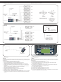
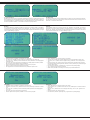
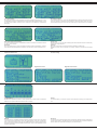
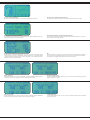
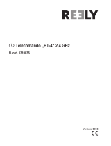
IT - Ricevitore e servo connessioni GB - Receiver and servo connections
per la batteria
to battery
per la batteria
to battery
Presa per caricar
Charging jack
Presa per caricar
Charging jack
Cavo interrutore
Switch harness
Cavo interrutore
Switch harness
Ricevitore
Receiver
Ricevitore
Receiver
Ricevitore
Receiver
CH6
CH6
CH6
CH5
CH4
CH3
CH2
CH2
CH2
CH1
CH1
CH1
Aileron modo
(2 separatamente servo
Aileron), CH 1 & 66
Flaperon mode
(dual aileron servo),
CH 1 & 6
Aileron e ap indipendenti
Independent Aileron & Flap
CH4
CH4
CH6
Gyro sensoriale (CH5), Direzionale (CH4)
Gyro sensory (CH5), Rudder (CH4)
Gyro di monitor
Optional Gyro system
Direzionale servo
Rudder servo
CH3
CH2
CH1
Batteria
Battery
Jumper
Binding jumper

4
Accendere
Power ON
Disabilita
Power OFF
IT
2. Procedure di accensione
1. Mettere insieme tutti gli elementi.
2. Accendere la trasmittente.
3. Collegare la batteria alla ricevente.
4. Il LED rosso si accende in modo permanente ricevitore, il che signica che l‘esistenza di un
vero e proprio segnale.
5. Il sistema è acceso e può essere utilizzato.
GB
2. Power on
1. Connect all parts.
2. Switch on the transmitter.
3. Connect the receiver battery.
4. The receiver red LED indicator is solid indicating the presence of a correct signal.
5. Use the radio system.
3. Apagar secuencia
1. Desconecte la batería del receptor
2. Apague el transmisor
3. Shut down
1. Disconnect the receiver battery.
2. Switch o the transmitter.
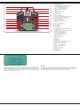
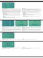
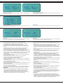
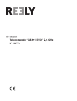
IT - Descripción gas sinistra
1 Antenna 2,4 GHz
2 Girare regolatoreVRB (Programmazione libera)
3 Interrutore B (Programmazione libera)
4 InterrutoreA (Programmazione libera)
5 Modo 2 = Stick gas / Direzionale
Modo 4 = Stick gas / Aileron
6 Gas trim
7 Modo 2 = Direzionale trim
Modo 4 = Aileron trim
8 Pulsante UP
9 Pulsante DOWN
10 LCD
11 Tasto di collegamento
12 Girare regolatore VAA (Programmazione libera)
13 Interrutore C (Programmazione libera)
14 Interrutore D (Programmazione libera)
15 Aggancion cinghia
16 Modo 2 = Stick aileron / elevator
Modo 4 = Stick elevator / direzionale
17 Elevator trim
18 Modo 2 = Aileron trim
Modo 4 = Direzionale trim
19 Invio (ENTER)
20 Exit / indietro
21 Interruttore on/o
22 Collegamento per cavo Simulatore
23 Vano Batterie
GB - Denition of key funktions throttle left
1 2,4 GHz Antenna
2 Rotary poteniometer VRB (free programmable)
3 Switch B (free programmable)
4 Switch A (free programmable)
5 Mode 2 = Throttle/Rudder stick
Mode 4 = Throttle/Aileron stick
6 Throttle Trim
7 Mode 2 = Rudder Trim
Mode 4 = Aileron Trim
8 Key up
9 Key down
10 LCD Display
11 Bonding button
12 Rotary poteniometer VAA (free programmable)
13 Switch C (free programmable)
14 Switch D (free programmable)
15 Hook
16 Mode 2 = Aileron/Elevator stick
Mode 4 = Elevator/Rudder stick
17 Elevator Trim
18 Mode 2 = Aileron Trim
Mode 4 = Rudder Trim
19 Enter button
20 Exit / Back button
21 Power switch
22 Simulator connecter
23 Battery box
22
23
1
11
12
13
14
15
16
17
18
19
20
2
3
4
5
6
7
8
9
10
21

5
Attenzione:
A causa di un dispositivo di sicurezza supplementare devono essere tutti quattro in-
teruttori del trasmittente in posizione OFF quando si accende il trasmittente. In caso
contrario, verrà visualizzato un avviso e un allarme acustico no a quando tutti gli
interruttori sono nella posizione corretta.
Warning:
For your safely, the 4 switches of the transmitter must be in their „o“ postition and
throttle stick must be the lowest position when turning the transmitter on. If not, a war-
ning screen will be displayed until all switches are in the right position.
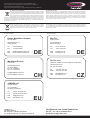
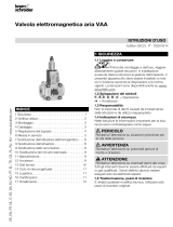
IT - Descripción gas destra
Antenna 2,4 GHz
2 Girare regolatoreVRB (Programmazione libera)
3 Interrutore B (Programmazione libera)
4 InterrutoreA (Programmazione libera)
5 Modo 1 = Stick elevator/direzionale
Modo 3 = Stick elevator/aileron
6 Elevator trim
7 Modo 1 = Aileron trim
Modo 3 = Direzionale trim
8 Pulsante UP
9 Pulsante DOWN
10 LCD
11 Tasto di collegamento
12 Girare regolatore VAA (Programmazione libera)
13 Interrutore C (Programmazione libera)
14 Interrutore D (Programmazione libera)
15 Aggancion cinghia
16 Modo 1 = Stick gas/aileron
Modo 3 = Stick gas/direzoinale
17 Gas trim
18 Modo 1 = Direzionale trim
Modo 3 = Aileron trim
19 Invio (ENTER)
20 Exit / indietro
21 Interruttore on/o
GB - Denition of key funktions throttle right
1 2,4 GHz Antenna
2 Rotary poteniometer VRB (free programmable)
3 Switch B (free programmable)
4 Switch A (free programmable)
5 Mode 1 = Elevator/Rudder stick
Mode 3 = Elevator/Aileron stick
6 Elevator Trim
7 Mode 1 = Aileron Trim
Mode 3 = Rudder Trim
8 Key up
9 Key down
10 LCD Display
11 Bonding button
12 Rotary poteniometer VAA (free programmable)
13 Switch C (free programmable)
14 Switch D (free programmable)
15 Hook
16 Mode 1 = Throttle/Aileron stick
Mode 3 = Throttle/Rudder stick
17 Throttle Trim
18 Mode 1 = Rudder Trim
Mode 3 = Aileron Trim
19 Enter button
20 Exit / Back button
21 Power switch
1
11
12
13
14
15
16
17
18
19
20
2
3
4
5
6
7
8
9
10
21

6
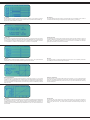
IT - Schermo principale
1. Programma Tipo AFHDS2A 1. Programm Typ AFHDS
2. Numero modello 2. Numero modello
3. Nome modello 3. Nome modello
4. Daten Information 4. Trimmare
5. Trimmare 5. Batteria / Pacco batteria
6. TX Batteria / Pacco batteria 6. Tipo di modello
7. RX Batteria / Pacco batteria 7. Trimmare
8. Tipo di modello
9. Trimmare
1. Nella nestra principale, si trovano Tipo di modulazione (ADFHDS2A e AFHDS) e le seguenti
informazioni:
2. Numero di modello selezionato (da 1 a 20): 20 modelli pos sono essere memorizzati nel
trasmittente, in modo da poter accedere o cambiare istantaneamente ai modelli desiderati.
3. Nome modello: è possibile dare ad ogni modello un nome (max. 8 caratteri) cosi i relativi modelli
sono più facilmente selezionabile.
4. AFHDS 2A: indica i dati della telemetria
AFHDS: le quattro barre di trimming indicano la posizione del trim
5. AFHDS 2A: le quattro barre di trimming indicano la posizione del trim
AFHDS: Capacità di visualizzazione Batteria/Pile trasmittente
6. AFHDS 2A: come 5 da AFHDS!
AFHDS: indica il tipo di modello scelto
7. AFHDS 2A: Capacità di visualizzazione Batteria/Pile trasmittente
AFHDS: quattro barre di trimming indicano la posizione del trim
8. AFHDS 2A: indica il tipo di modello scelto
GB - Main screen
1. Program type AFHDS2A 1. Program type AFHDS
2. Model number 2. Model number
3. Model name 3. Model name
4. Data feedback 4. Left trim
5. Left trim 5. Battery
6. TX Battery 6. Mode type
7. RX Battery 7. Right trim
8. Mode type
9. Right trim
1. Besides the modulations type (AFHDS2A or AFHDS), the main screen displays the following
information:
2. Selected model number (1 to 20): 20 dierent models can be saved in the transmitter allowing
you to instantly switch to 20 dierent models.
3. Model name: each model can be named with a 8 characters name that allow you to easily
recognize the associated models.
4. AFHDS 2A: Shows the data of telemetry
AFHDS: The four trimming bars show the position of the set value
5. AFHDS 2A: The four trimming bars show the position of the set value
AFHDS: Shows capacity of transmitter battery
6. AFHDS 2A: As in point 5 - AFHDS
AFHDS: Shows the chosen model type
7. AFHDS 2A: Shows capacity of receiver battery
AFHDS: The four trimming bars show the position of the set value
8. AFHDS 2A: Shows the chosen model type
1
3
4
5
6
7
2
3
4
5
6
7
8
9
1
2
Menu principale
Il menu principale è diviso in due parti, Sistema e Setup! Nel menu di sistema del trasmittente, è pos-
sibile impostare e salvare 20 modelli. Il menu delle funzioni è quindi utilizzato per impostare i singoli
modelli. Dalla schermata principale arrivate nel menu principale premendo il tasto „OK“ per un tem-
po prolungato. Per arrivare dal menu principale nelle impostazioni di sistema, premere e rilasciare
il tasto „OK“. Il punto desiderato del sistema di sotto-menu selezionate con il tasto „UP“ o „DOWN“
scorrere no al punto di programma appropriato e selezionarla premendo il tasto „OK“. Le rispettive
impostazioni vengono confermati e eettuati dal tasto „CANNEL“ . La maggior parte delle schermate
seguenti saranno trattati in base a questo schema. Ogni impostazione di memoria va confermato
con il tasto„OK“.
Per uscire dalla voce di menu corrente, premere il tasto „OK“.
1. Sceglere i parametri con il tasto „Enter“.
2. Utilizzare la manopola „UP“ e „Down“ per modi care il valore del parametro selezionato.
3. Premere il pulsante „OK“ per salvare le impostazioni e tornare al parametro precedente.
4. Premere il pulsante „Cancel“ per uscire senza salvare le nuove impostazioni e tornare al
parametro precedente.
Per tornare alla schermata precedente, premere il tasto „Cancel“. Premendo ripetutamente il tasto
è possibile scorrere indietro no alla schermata principale.
Main Menu
The main menu is seperated into two sections, system and functions setup. The system menu
allows you to set up the transmitter and manage the 20 models. The function menu is used to set up
each model seperately. To enter the main menu, long press the „OK„ . Then use the „Up“ and „Down“
Key to select the desired submenue and press again „OK“. Then, use the „Up“ and „Down“key to
select the desired submenu and press again „OK“.
Most of following screens work according to this simple scheme:
1. Use the „OK“ key to select the parameter to modify.
2. Use the „UP“ and „Down“ key to modify the value of the selected parameter.
3. Long Press the „Cancel“ key to exit and save the new parameters.
4. Short Press the „Cancel“ key to exit without saving the new parameters.
To return to the previous screen, press the „Cancel“ key. You can
repeat that operation until the main screen.
Impostazioni di sistema System settings

7
IT - Seleziona il modello
Questa funzione consente di selezionare un modello attivo dei 20 modelli disponibili. È possibile
passare tra 20 diversi modelli, salvare tutti i parametri necessari, e subito volare.
GB - Model select
Use this function to select the active model among the 20 available models. Doing so, you can set
up and save all required parameters to y 20 dierent models and switch instantly between them.
Nome modello
Utilizzare questa funzione per assegnare un nome al modello selezionato. Selezionare le lettere
ruotando il tasto „UP“ o „DOWN“, poi premere „OK“ per cambiare la lettera del nome.
Model name
Use this function to chance the name associated with the currently selected model. Press „OK“ to
select the letter of the name to change then use the “UP“ or “DOWN“ key to change the selected
letter.
Seleziona il tipo
Utilizzare questa funzione per selezionare il tipo di aereo o un elicottero e le opzioni di gestione
corrente del modello. Il menu „Setup Funzioni“ è visualizzato secondo queste impostazioni. Il tras-
mittente supporta aerei con coda a V ed elicotteri con Pitch sso o variabile e Swash AFT (collettivo
e ciclico Pitch Mixing) 90°, 120° and140°.
Type select
AFT (Collective und Cyclic Pitch Mixing) 90 °, 120 ° and140 °. Use this function to select the type of
aircraft or helicopter the current model is controlling. The „Functions setup“ menu will be lled accor-
dingly. The transmitter supports airplanes (including V-tail con guration), xed and variable pitch
helicopters and Swash AFT (Collective and Cyclic Pitch Mixing) 90°, 120° and 140°.
Copia modello
Questa funzione consente di copiare le impostazioni di un modello a un altro. Le impostazioni del
modello di destinazione (se presenti) vanno cancellato e sostituiti con le nuove impostazioni copiate.
Poiché questo comando consente di eliminare le impostazioni esistenti, è richiesta una conferma.
Premere il tasto „OK“ per eseguire la copia, selezionare „Sì“ con la manopola e premere „OK“ per
confermare la copia.
Model copy
Use this function to copy one model settings to another. The target model settings will be deleted
and replaced by the source model settings. Since this command is destructive, a conrmation will
be asked. Press „OK“ to execute the copy, select „Yes“ with “UP“ or “DOWN“ key then press „OK“
again to conrm.

8
IT - Ripristina modello
Questa funzione ripristina tutte le impostazioni predenite del modello e cancella quelli attuali. Tutti
gli altri modelli non sono coinvolti da questo processo. Questo può essere utile quando un Setup non
ha il risultato desiderato, e si desidera eseguire un inizio delle impostazioni. Poiché questa funzione
cancella le impostazioni esistenti, vi sarà chiesto di confermare quest’operazione.
GB - Model reset
This function will reset the currently selected model to its default. The other models will not be aec-
ted. This can be useful when a setup is going nowhere and need a fresh start. Since this function is
destructive, a conrmation will be asked.
• Selezionare il menu „RX-Setup“ é confermare con il tasto „OK“.
• La voce di menu „AFHDS 2A“ é gia marcato é può essere attivato con il tasto „OK“.
• Con il tasto „UP“ o „DOWN“ può essere disattivato la codica „AFHDS 2A“. Sul display appare
l’indicazione „O“.
• Con il tasto „OK“ viene memorizzato l´impostazione é sul display appare la codica „AFHDS“.
Qui non possono essere eettuati ulteriori impostazioni.
• Premere ripetutamente il pulsante „CANCEL“ si ritorna al menu principale.
• Dopo di che deve essere eseguito il processo di binding.
• Per riprogrammare nuovamente la trasmittente su „AFHDS 2A“ ripetere il tutto.
• Select ‚„RX Setup“ menu and and conrm by „OK“ button
• The menu item „AFHDS 2A“ is already selected and can be activated with the button „OK“.
• The buttons „UP“ or „DOWN“ switch the digital encoding „AFHDS 2A“ o. The display shows
„O“.
• Pushing the button „OK“ saves the setting and the display shows the digital code „AFHDS“. If
the transmitter works with the digital code „AFHDS“, the menu „RX Setup“ only shows the digital
code as a setting option.
• Push the button „CANCEL“ repeatedly until you get back to the operating display.
• Then, a binding process has to be performed.
• Switch back to „AFHDS 2A“ according to the same principle as described above.
PPM Output
• Selezionare il menu „RX Setup“ e confermare con il tasto „OK“.
• Selezionare con il tasto „UP“ é „DOWN“ la voce del menu „PPM-Output“ é attivarlo con il tasto
„OK“.
• Con il tasto „UP“ é „DOWN“ può essere modicata questa impostazione. Sul display appare
„O“ o „On“.
• Con il tasto „OK“ viene memorizzata l‘ impostazione.
• Premere ripetutamente il pulsante „CANCEL“ si ritorna al menu principale.
PPM Output
• Select ‚„RX Setup“ menu and and conrm by „OK“ button
• Use the buttons „UP“ or „DOWN“ to select the menu item „PPM-Output“ and activate it with the
button „OK“.
• With the „UP“ or „DOWN“ button can be changed this setting. „OFF“ or „ON“ appears on the
display.
• Pushing the button „OK“ saves the setting.
• Push the button „CANCEL“ repeatedly until you get back to the operating display.
RX-Setup
Con questo trasmittente é possibile controllare la ricevente con la codica „AFHDS“ é „AFHDS2A“.
La trasmittente e impostata sulla ricevente inclusa „AFHDS2A“. Per usare la ricevente „AFHDS“ la
trasmittente deve essere cambiata é la ricevente deve essere collegata alla trasmittente. Si prega di
notare il capitolo Binding su pagina 3.
RX Setup
The transmitter enables you to receivers with the code „AFHDS 2A“ and „AFHDS“. Ex works, the
transmitter is set to the enclosed „AFHDS 2A“-encoded receiver. If you want to operate a receiver
with the code „AFHDS“, the transmitter must be switched rst and then the receiver must be bound
to the transmitter. Please refer to the section Binding on page. 3

9
IT - Tensione del ricevente
A secondo della tensione della ricevente usata possono essere impostati in questo menu i valori di
tensione, in cui la trasmittente mostra visivamente e acusticamente una avvertimento di sottocarica
della batteria ricevente,
Dal momento che i valori di tensione regolabili sono indipendenti, può essere necessario aumentare
il valore di tensione per la batteria caricata, per inserire in seguito anche i valori di allarme più alti.
Se i limiti dei valori impostati sono inferiore, lampeggia quando si utilizza la trasmittente nel display il
simbolo della batteria per la batteria ricevente e il trasmittente emette toni di avviso o toni di allarme.
• Bassa tensione:
Impostare il valore minimo di tensione. Viene emesso un allarme acustico e il simbolo della
batteria ricevente nel display lampeggia, quando l’attuale valore di tensione della batteria é
inferiore a questo valore.
• Tensione di allarme:
Impostare la tensione di allarme. Viene emesso un allarme acustico e il simbolo della batteria
ricevente nel display lampeggia, quando l’attuale valore di tensione della batteria é inferiore a
questo valore.
• Alta tensione:
Impostare il valore massimo di tensione. La batteria é completamente carica, quando il valore
eettivo della tensione della batteria é uguale a questo valore.
GB - RX Battery
Depending on the receiver voltage supply used, this menu can be used to set the voltage values
where the remote control visually and acoustically displays threatening deep discharge.
Since the adjustable voltage values depend on each other, it may be required to increase the voltage
value for a fully charged rechargeable battery rst, to then be able to enter higher alarm values as
well.
If the set thresholds are undercut, the battery icon for the receiver battery will ash at operation of the
remote control and the remote control transmitter will make warning or alarm sounds.
• Low voltage:
set the minimum voltage value. The battery is empty when the actual battery voltage value is
lower than this value.
• Alarm voltage:
set the alarm voltage. an audible alarm rings and the receiver battery icon in the top tray blinks
when actual battery voltage value is lower than this value.
• High voltage:
set the maximum voltage value. The battery is in full charge state when the actual battery
voltage is equal to this value.
Fail Safe
Il trasmittente ore. In caso di una perdita si segnale, la possibilità di posizionare i servi automatica-
mente in una posizione specica. Ad esempio, un aliante che si trova fuori della portata il motore si
spegne é inizia a volare in cerchio.
Impostazioni:
Premere brevemente „OK“, selezionare il canale che si desidera. Con „UP“ o „DOWN“ può cambi-
are il canale da „OFF“ a „ON“ o usare invertito. Per immettere l’impostazione desiderata, spostare
la leva di controllo nella posizione desiderata e premere il pulsante „CANCEL“. Il display ritorna
all’elenco die canali e mostra il valore percentuale del canale selezionato. Premendo nuovamente il
pulsante „CANCEL“ vengono memorizzati i valori.
Fail Safe
This function is used for setting the data of failsafe. Once the signal of receiver is lost, the one
or more servos will back to preset position. „turn o“ means the relevant servos will keep the last
position when the signal is lost.
Setting methods:
Short press „OK“, choose one channel to set failsafe function, if the channel is in the needed po-
sition, and keep it, short press „OK“, than the position of servo will be saved. „ALL Channels“ is
used for setting all activated channels at a time. Press „Chancel“ after nishing all setting to save
the failsaft data.
Lista sensore
Se dovrebbe essere collegato a un I-BUS-Ricevente più sensori (no a 15 sensori), questi sensori
vengono visualizzati in questo menu.
Sensor list
If shows al sensors`type, code and value, it can connect 15 sensors at most.
Selezionare il sensore
Il schermo principale può mostrare 3 valori die sensori, con questa funzione può selezionare vari
sensori, che devono essere visualizzati.
Choose sensor
Main screen can show 3 sensors‘ value, this function can select sensor which need to show, if you
don‘t select sensor, it will show teh default one.

10
DE -Speed-distance
Sensore di velocità:
Utilizzare il sensore desiderato. Se non e selezionato uno, viene disattivata questa funzione.
Impostazione sensore – velocità:
Regolare il sensore di velocità corrispondente della distanza di un veicolo. Questo valore viene
utilizzato per controllare la velocità verticale ed il sensore-contachilometri.
Reset Odometer:
Toccare il „Reset Odometer 1“ o „Reset Odometer 2“ per azzerare il relativo contachilometri.
Odometer 1: é per rilevare la distanza percorsa in tempo del veicolo.
Odometer 2: é per rilevare la distanza percorsa del veicolo.
GB -Speed-distance
Speed sensor:
Select the rotation speed sensor to use. If none is seledted, this function is disabled.
Set rotation length:
Set the vehicle travel distance corresponding to one rotation speed sensor. This distance is used to
control the virtual speed and odometers sensor.
Reset odometer:
Touch „Reset odometer 1“ or „Reset odometer 2“ to reset the corres ponding odometer.
Odometer 1: it is used for recording the distance traveled by the vehicle on time.
Odometer 2: it is used for recording the distance traveled by the vehicle.
i-Bus Setup
Questa funzione viene utilizzata per amplicare il canale dati.
i-Bus Setup
This function is used to expand data channel.
Servos freq
Con il tasto „UP“ o „DOWN“ può essere impostata la frequenza-servo desiderata. Se viene premuto
é tenuto premuto il tasto „OK“ vengono azionati i parametri.
Attenzione!
Nei servi analogici non può essere superata la frequenza-servo 50 Hz, altrimenti vengono distrutti i
servi. Se si utilizza servi digitali, l’impostazione del valore dipende dal valore massimo del servo più
lento, il valore impostato é ecace per tutte le uscite della ricevente.
Servos freq
Use the buttons „UP“ or „DOWN“ to set the desired servo control frequency. If the button „OK“ is
pushed and held, the factory parameters are called.
Important!
When using analogue servos, the servo control frequency must not exceed 50 Hz, since the servos
are otherwise destroyed. If you operate only digital servos at the receiver, the value to be set is
according to the maximum value of the slowest servo, since the set value is eective for all receiver
outputs.
Modalità-Master
Questa funzione consente di utilizzare con l´aiuto di un cavo insegnante-studente di collegare in-
sieme due trasmettitori sulla porta formatrice sul retro del trasmittente. Uno è il trasmittente mas-
ter e l‘altro è il trasmittente slave. Se la modalità insegnantestudente (allenatore) è con gurato,
il passaggio da maestro ad allievo viene attivato attraverso lo pulsante associato sul trasmittente
master. Il trasmittente slave può essere controllato attraverso il segnale del trasmittente master.
Una volta che il trasmittente slave è spenta, il trasmittente master, riprende il controllo completo
del modello e può salvare il modello in una situazione pericolosa.
Trainer mode
This function allows you to connect 2 transmitters together using a dedicated cable (No. 091551)
connected to the back interface. One is the instructor (Trainer) and the other is the student (Stu-
dent). Once enabled, switching on the selected trainer switch will set up the remote as the inst-
ructor and use the student signal to control the model. As soon as the trainer switch is turned o,
the instructor regains control and can for example recover the model from a hazardous position.

11
IT - Modalità- Slave
Questa funzione è disponibile in combinazione con la modalità Master. Per l’uso della
modalita´master/slave il trasmittente slave deve essere spento! Una volta attivato, tutte le
impostazioni del modello sono annullate e i comandi di controllo sono inviati direttamente al
trasmittente master attraverso, il quale i modelli possono poi essere controllati con le sue impos-
tazioni. Così il trasmittente slave funziona con qualsiasi ricevente che è legato al trasmittente
master per lo scambio di dati e anche per il controllo di ogni stazione memorizzata sul modello
master. Per evitare incidenti o problemi nella modalità Master/Slave il trasmittente master annulla
in quel momento tutte le impostazioni del trasmittente slave e usa solamente le sue impostazioni.
GB - Student mode
This function works together with the trainer mode. Once enabled, all model settings are by-
passed and the sticks position is send directly to the instructor‘s transmitter. At that time, the
student transmitter must not control any model directly and any receiver bound to the student
transmitter must be turned o. Bypassing all student settings allows both student and instructor
to share the instructor settings to avoid any glitch when switching between the student and his
instructor.
Modalità di controllo
Con questa funzione è possibile scegliere tra 4 diverse modalità di controllo. I primi 4 canali sono
ordinati per i comandi di controllo ssi, le quali è possibile selezionare in base alle proprie abitu-
dini di volo (ad esempio: gas a sinistra o destra).
Stick mode
With this function, you can choose among 4 dierent sticks modes. The 4 rst channels are
mapped to the selected sticks according to your ying habits (left or right handed for example).
Versione rmware
Questo schermo mostra la versione Firmware e la data della versione. Ciò consente di determi-
nare se eventualmente è disponibile un aggiornamento o una versione più recente (vedi aggior-
namento del rmware).
Firmware version
This screen displays the rmware version and date. This allows you to know if a newer version
is as avialable for update (see below).
Luminosità LCD
La luminosità dello schermo può essere regolata, per adeguare il display alle condizioni
d’illuminazione dell‘ambiente.
LCD brightness
Adjust the screen contrast according to the surrounding light environment.

12
Reset sulle impostazione di fabbrica
Con l’aiuto di questa funzione ha la possibilità di resettare tutti i dati di tutti modelli di memoria
con solo un unico comando.
Attenzione!
Se si usa questa funzione, vengono cancellati tutti i dati dei modelli e impostazioni! La trasmit-
tente viene riportata alla impostazione di fabbrica é tutti i dati devono essere impostati di nuovo.
Factory reset
With this function you have the option of deleting all the data of all model memories to their factory
settings with a single command.
Attention!
When you call this function, all previously entered model data and settings are
deleted! The remote control is returned to the delivery condition and all data must be entered
again.
IT - Firmware Update
Per aggiornare il Software sulla trasmittente, deve essere collegato la trasmittente con un cavo
interface-USB al computer. La trasmittente deve essere portata nella modalità di Update, in modo
che i dati vengono trasferiti. Assicurarsi, che le riceventi che sono collegati con la trasmittente
sono spenti.
GB - Firmware update
Prior activating this function, connect the USB cable between the back interface of the transmitter
and a PC computer. A conrmation will be asked since all functions will be halted. Turn o any
receiver before entering this mode. To exit this mode, simply turn o then back on the transmitter.
Impostazioni delle funzioni Functions settings
Inversione Servo
Questa funzione permette di invertire un canale. Impostare tutti i canali in modo che la direzione
della leva servo rispetta le indicazioni del timone del suo modello.
Reverse
This funktion allows you to reverse a channel. Set all channels according to your model mecha-
nics.
Regolazione dell‘aereo Regolazione dell‘elicottero
Endpoint
Con questa funzione, è possibile impostare le escursioni massime di ciascun servo che è asseg-
nato a questo canale. Selezionare il numero del canale premendo il tasto „OK“ e modicare il
valore in percentuale ruotando il tasto „OK“. Si cambia la direzione di controllo, ruotando la leva
di controllo scegliendo la direzione desiderata. Selezionare i valori in modo individuale secondo
le esigenze del modello.
End points
This function sets the lower and upper extents of all channels. Select the channel number with the
„OK“ key and the lower or upper extenby moving the corresponding stick or variator to the desired
direction. Select each extent value according to your model mechanics.

13
IT - Display
Questa schermata visualizza lo stato di tutti e sei i canali, il modo in cui sono legati con il trasmit-
tente del rispettivo modello selezionato. Esso contiene tutte le impostazioni della modalità e gli
algoritmi, se il modo studente non è attivato.
GB - Display
This screen displays the status of all the 6 channels like they are transmitter to the model. It‘s
includes all the mode settings and algorithms if the student mode is not activated.
Canali – Aux
Questa funzione consente di selezionare la base dei canali 5 e 6 . Essa può essere una manopo-
la o un interruttore. Quando un interruttore è stato selezionato (Modello di Volo), tramite questo la
funzione scelta viene attivata o disattivata. Se è usato un elicottero con Pitch variabile, il canale 6
non e´disponibile. Se è attivato il rotore dell’elicottero, il canale 5 non e´disponibile.
Auciliary channels
This function let you choose the source of the channels 5 and 6. It can be a variator or a switch. If
a switch is selected, an o switch will tranmit the lower extent of the channel an an on switch the
upper extent. If a variable pitch helikopter is in use, the channel 6 is unavailable. If a helicopter
gyroscope is activated, the channel 5 is unavailable.
Subtrimm
Questa funzione consente di regolare la posizione neutra di ogni servo. Ciò è particolarmente
utile quando il centro non può essere nemente regolata meccanicamente.
Sub trim
This funktion allows you to adjust the middle point of each servo. This is especially useful when
this middle point cannot be mechanically ne adjusted.
Dualrate / Exponential
Con questa funzione, è possibile modi care l‘Expo e la dual rate dei canali 1, 2 e 4 sia nella
modalità normale sia nella modalità sport. Utilizzare l‘interruttore della modalità di volo (SWA) per
cambiare tra la modalità Normale e Sport. La Rate seleziona il coe ciente di pendenza deside-
rata e la linearità della curva esponenziale. Ciò è molto utile per ridurre la sensibilità in prossimità
del punto neutro.
Dual rate / exponential
This function lets you set up the transfer function of the channel 1, 2, und 4 in both normal and
sport mode. Use the y mode switch to change mode. The rate selects the desired slope coeci-
ent and the exponential the linearity of the curve. This is very useful to decrease the sensitivity
near the middle point.
Curva Gas
Questa funzione è utilizzata per impostare la curva di trasmissione nella funzione del gas (Canale
3) in modalità normale e di inattività. Utilizzare l‘interruttore di standby (SWB) per cambiare la
modalità da Normale a Idle-up. 5 punti importanti possono essere impostati qui. Ad esempio, un
principiante può ridurre la sensibilità del corpo sfarfallato di 0,5, 10, 15 e 20% e mantenere cosi
la sua linearità.
Throttle curve
This function sets up the transfer curve of the throttle (channel 3) in both normal and idle up
modes. Use the idle mode switch to change mode. 5 key points can be adjusted. For example, a
beginner may set them to 0,5, 10, 15 and 20% to decrease the throttle sensitivity and keep its
linearity.

14
IT - Curva - Pitch (solo elicotteri)
Questa funzione è simile alla funzione di „curva del gas“ e visualizza la curva Pitch.
GB - Pitch curve (variable pitch helicopter only)
This function is similar to the „Throttle curve“ and sets up the transfer curve of the pitch.
Swash AFR (variable Pitch solo elicotteri)
Con questa funzione, è possibile regolare il valore di Roll, Nick e Pitch nel Swash AFR. Per inver-
tirlo deve essere selezionato un valore negativo.
Swash AFR (variable pitch with Swash AFT helicopter only)
This function sets the proportion of aileron, elevator and pitch in the Swash AFR. To invert one of
them, a negative value must be selected.
Mix
Questa funzione consente di programmare no a 3 mixer, che si possono mescolare i diversi
canali e funzioni di controllo. Il canale Master cambia il canale Slave. Le percentuali positive
e negative modicano il riferimento sopra e sotto il valore medio. I turni di oset modi cano il
canale slave di una percentuale specica.
Mix
This function allows you to program up to 3 custom channel mixes. The master channel will alter
the slave channel. The positive and negative mix set the amount of alteration above and below
the middle point. The oset shifts the slave channel by a certain amount.
Elevon (solo aereo)
Attivare questa funzione se si vola un modello delta o monoala. Impostare le parte di l’alettone-
(canale 1) é timone di quota- (canale 2) nel mixer a secondo del suo modello.
GB - Elevon (Airplane only)
For the model without tail and the delta wing, you can set mix control rates of Aileron (CH1) and
Elevator (CH2) by this function.
Coda a V (solo aerei)
Attivare questa funzione se si vola un aereo con una coda a V. Impostare la frazione dell’alettone
(canale 1) e l‘ascensore (canale 2) nel Mix in conformità con il Suo modello.
V-tail (Airplane only)
For the model without the V-tail, you can set mix control rates of Elevator (CH2) and Rudder
(CH4) by this function.

15
IT - Rotante (solo elicotteri)
Questa funzione consente di attivare il rotante sul canale 5 e impostare i valori sia per la posizi-
one normale e sia di inattività.
GB - Gyroscope (Helicopter only)
This function allows you to activate the gyroscope on the channel 5 and to set up its value for
both normal and idle up modes.
Assegnazione interuttori
Con questa funzione, è possibile assegnare varie modalità di volo ad un interruttore, con il quale
può potete passare da una funzione ad un altra.
Switches assign
This function lets you assign a switch to conrol the y mode, idle mode and throttle hold functions.
Autorotazione
Questa funzione consente di attivare l‘auto-rotazione e di scegliere il suo valore. Una volta attiva-
to, l‘acceleratore viene ignorato e solo i valori selezionati vengono trasmessi.
Throttle hold
This function allows you to activate the throttle hold and to choose its value. Once engaged, the
throttle stick is ignored and only the selected value is transmitted.
Istruzioni per la sicurezza
● Leggete attentamente le istruzioni prima di usare il radiocomando.
● Se si utilizza modelli a controllo remoto per la prima volta, si consiglia di
necessariamente un modellista esperto per chiedere aiuto.
● Questo radiocomando é progettato e costruito per in impiego modellistico.
● Cùi Jamara non si assume nessuna responsabilità per li suo impiego in altri
campi.
● I modelli radiocomandati non solo giocalloli, per cui il loro uso é limitato ai
bambini ed in ogni caso sollo il controllo e la responsabilità di adulti.
● Per il funzionamento del prodotto richiede competenze e abilità manuale buona.
Guasti o lasciarlo bagnato, il prodotto può essere danneggiato e ferito.
● Dato che ne il fabbricante ne il rivenditore possono controllare che l‘uso rispetti
queste istruzioni, va da sé che ambedue riutano totalmente ogni responsabilità
per danni a cose oi persone causate durante l‘uso di qualsiasi modello
radiocomandato.
● Inoltre, il funzionamento del sistema ricevente senza interruttore trasmettitore
può causare problemi e lesioni.
● Usate la radicomandi con cautela. Rispettate le norme di sicurezza.
● Accendere la trasmittente prima e poi la sistema ricevente.
Quando si spegne si attenga con l‘ordine invertito.
● Usate solo riceventi originali Jamara.. La radiocomandiz non è compatibile con
altre riceventi 2,4 GHz.
● Tenete sempre pulita e spolverata la vostra radio mantenendola sempre in luoghi
asciutti e protetti dalle temperature.
● Usate la trasmittente solo tra -10 no a +40°C.
● Usare caricatori Jamara per il caricamento delle batterie. Rispettate le norme del
fornitore durante la carica.
● Evitare urti e pressione di carica. Controllare regolarmente il trasmittente, il
ricevitore e i cavi su danneggiamenti.
● Non usare mai pezzi danneggiati o pezzi che si sono bagnati in passato, anche
se oggi sono asciutti. Chiamare il nostro servizio di assistenza o sostituire i
ATTENZIONE!
● Questo prodotto non è destinato ad essere utilizzato da persone (bambini
compresi) con capacità fisiche limitate, con limitazioni sensoriale o mentali
oppure mancanza di esperienza e/o di conoscenza. A meno che siano
sorvegliate da una persona responsabile della loro sicurezza o ricevano
istruzioni su come usare il prodotto in modo corretto. Bambini devono essere
supervisionati per assicurare che non giocano con l’apparecchio.
Safety Information
● Read these instructions carefully before use paying particular attention to the
safety notes.
● If this is your first venture into radio controlled modelling we strongly recommend
that you seek the help of an experienced modeller before you begin.
● This Radio control system has been exclusively designed for use with models
designed to be remotely controlled and as such may only be legally operated as
such.
● The company JAMARA accept no responsibility whatsoever if his product is used
in any other way.
● Radio Controlled models, in particular aircraft, are not toys and as such and
should only be operated by children or youths if closely supervised by a
responsible adult.
● Building and operating such models requires a degree of skill, understanding
and technical knowhow as well as a responsible attitude. Faults in the
construction or irresponsible behaviour could lead to serious damage or injury.
● As neither the manufacturer or retailer has any influence over the correct use of
modelling products we wish to emphasise these safety instructions and will in no
way be held responsible for the misuse of our products.
● Please be aware that the receiver system can also create a danger if operated
when the transmitter is not switched on.
● Always operate the transmitter with extreme caution and follow the instructions
listed here.
● Always switch the transmitter on before the receiver and switch off in the
opposite order.
● Only use our original receivers as any other brand of 2.4 GHz receivers will not
bond to our transmitters.
● Protect the system from dust, dirt and moisture.
● Never expose the system to extreme heat, cold or vibration. The system should
only be operated between -10° and + 40°C.
● Use a good quality charger selected from our range and follow the battery
manufacturers instructions.
● Avoid exposing the system to impact or vibration and inspect all of the
components regularly for damage to the casing, plugs, sockets and cables.
● If any component gets damaged or is exposed to water do not use it even if it has
been dried out! Any such component should be replaced or returned to our
service department.
ATTENTION!
● This product is not intended for use by individuals (including children) with
reduced physical, sensory or mental capabilities or lack of experience and / or
knowledge, unless they are supervised by a person responsible for their safety
and is able to give instructions about how the product should be used. Children
should be supervised to ensure that they do not play with the product.

Irrtum und technische Änderungen vorbehalten. Copyright JAMARA e.K. 2021
Kopie und Nachdruck, auch auszugsweise, nur mit Genehmigung von JAMARA e. K.
All rights reserved. Copyright JAMARA e.K. 2021
Copying or reproduction in whole or part, only with the expressed permission of JAMARA e.K.
JAMARA e.K.
Inh. Manuel Natterer
Am Lauerbühl 5 - DE-88317 Aichstetten
Tel. +49 (0) 75 65/94 12-0 - Fax +49 (0) 75 65/94 12-23
[email protected] ● www.jamara.com
Service - Tel. +49 (0) 75 65/94 12-777
kundenservice@ jamara.com
IT - Centro assistenza GB - Service centre
IT - Istruzioni per lo smaltimento
Batterie e gli accumulatori non devono essere smaltiti nei riuti domestici, ma devo-
no essere smaltiti separatamente. Siete obbligati di eseguire lo smaltimento profes-
sionale delle batterie vecchie (raccolta dierenziata). È possibile restituire le batterie
dopo l’uso gratuitamente nelle attività commerciali. Dato che le batterie contengono
delle sostanze, che provocano irritazione, possono causare allergie o sono altamen-
te reattivi, la raccolta dierenziata e il riciclaggio sono importanti per l’ambiente e la sua salute. Se
le batterie, a disotto del “bidone a ruote cancellato” sono segnati con un simbolo chimico Hg, Cd o
Pb, signica che questi contengono più di 0,0005 % Mercurio (Hg), più di 0,002 % Cadmio (Cd) o
piu di 0,004 % Piombo (Pb).
GB - Disposal restrictions
Batteries and accumulators must not be disposed of in domestic waste. You are obliged to dispose
of batteries (seperate collection) appropriately. After use you can return batteries free of charge to
the retail store. As batteries contain substances that can be irritant, can cause allergy and are highly
reactive, separate collections and proper recycling is important to the environment and to your
health. If the batteries are marked with a chemical symbol Hg, Cd or Pb below the crossed-out waste
bin on wheels it refers to that more than 0.0005% of mercury (Hg), more than 0.002% of cadmium
(Cd) or more than 0.004% Lead (Pb) is included.
IT - Istruzioni per lo smaltimento
Apparecchi elettrici non devono essere smaltiti nei riuti domestici, ma devono
essere smaltiti separatamente. Siete obbligati di rimuovere le batterie e portare
l´apparecchi elettrici vecchi ai punti di raccolta comunali. Qualora ci sono dati perso-
nali sul apparecchio elettrico, devono essere rimossi da voi stessi.
GB - Disposal restrictions
Electrical appliances must not be disposed of in domestic waste and must be disposed of separately.
You are obliged to take out the batteries, if possible, and to dispose of the electrical equipment at
the communal collection points. Should personal data be stored on the electrical appliance you must
remove them by yourself.
Reitter Modellbau Versand
Patricia Reitter
Degerfeldstrasse 11
72461 Albstadt
Tel 07432 9802700
Fax 07432 2009594
Mail [email protected]
Web www.modellbauversand.de
Modellbau-Zentral
Peter Hofer
Bresteneggstrasse 2
CH -6460 Altdorf,
Tel. +41 794296225
Fax +41 418700213
www.modellbau-zentral.ch
PenTec s.r.o.
distributor Jamara for Czech Republic and Slovakia
Veleslavínská 30/19
CZ -162 00 Praha 6
Tel +420 235 364 664
Mobil. +420 739 075 380
Mail servis@topdrony.cz
Web www.topdrony.cz
Bay-Tec
Martin Schaaf
Am Bahndamm 6
86650 Wemding
Tel 07151 5002192
Fax 07151 5002193
Mail [email protected]
Web www.bay-tec.de
DE DE
JAMARA e.K.
Manuel Natterer
Am Lauerbühl 5
DE-88317 Aichstetten
Tel +49 (0) 75 65/94 12-0
Fax +49 (0) 75 65/94 12-23
Mail [email protected]
Web www.jamara.com EU
CH CZ
-
 1
1
-
 2
2
-
 3
3
-
 4
4
-
 5
5
-
 6
6
-
 7
7
-
 8
8
-
 9
9
-
 10
10
-
 11
11
-
 12
12
-
 13
13
-
 14
14
-
 15
15
-
 16
16


Jamara FCX6 Pro Tel Istruzioni per l'uso
- Categoria
- Giocattoli telecomandati
- Tipo
- Istruzioni per l'uso
in altre lingue
- English: Jamara FCX6 Pro Tel Operating instructions
- português: Jamara FCX6 Pro Tel Instruções de operação
Documenti correlati
Altri documenti
-
 Reely 1310037 Istruzioni per l'uso
-
 Reely 1414497 Istruzioni per l'uso
-
 Reely 1410409 Istruzioni per l'uso
-
 Reely 1310036 Istruzioni per l'uso
-
 Reely 1897778 Istruzioni per l'uso
-
Blade SR Manuale utente
-
E-flite EFL01150 Manuale del proprietario
-
Spektrum DX5e Manuale del proprietario
-
E-flite Blade SR Manuale utente
-
 Kromschroder VAA Istruzioni per l'uso


