Sirius Satellite Radio EMSLT958 EM Manuale utente
- Tipo
- Manuale utente

INFORMAZIONI COMMERCIALI PER I CONSUMATORI
COMMERCIAL INFORMATION FOR THE CONSUMER
INFORMATIONS COMMERCIALES POUR LE CLIENT
INFORMACIONES COMERCIALES PARA EL CLIENTE
HANDELSINFORMATIONEN FÜR DEN KUNDEN
COMMERCIËLE INFORMATIES VOOR DE KLANT
INFORMAZIONI TECNICHE
TECHNICAL INFORMATION
INFORMATION TECHNIQUES
INFORMACIONES TÉCNICAS
TECHNISCHE INFORMATIONEN
TECHNISCHE INFORMATIES
TYPE:FSED-FSEB-FSEA
IT
GB
F
E
D
NL
ISTRUZIONI PER INSTALLAZIONE USO E MANUTENZIONE
INSTALLATION, USE AND MAINTENANCE INSTRUCTION
INSTRUCTIONS D’UTILISATION ET AVIS DE MONTAGE
INSTRUCCIONES DE USO Y DE MONTAJE
BEDIENUNGSANLEITUNG MIT MONTAGEANWEISUNGEN
GEBRUIKSAANWIJZIGING
SLT950EM-SLT951EM-SLT952EM
SLT953EM-SLT950.1-SLT951.1-SLT950.1EM
SLT951.1EM
SLT958EM-SLT958.1

2

3
Il simbolo sul prodotto o sulla confezione indica che il prodotto non deve essere
considerato come un normale riuto domestico, ma deve essere portato nel punto
di raccolta appropriato per il riciclaggio di apparecchiature elettriche ed elettroni-
che. Provvedendo a smaltire questo prodotto in modo appropriato, si contribuisce
a evitare potenziali conseguenze negative per l’ambiente e per la salute, che po-
trebbero derivare da uno smaltimento inadeguato del prodotto. Per informazio-
ni più dettagliate sul riciclaggio di questo prodotto, contattare l’ucio comuna-
le, il servizio locale di smaltimento riuti o il negozio in cui è stato acquistato il
prodotto. Questo elettrodomestico è marcato conformemente alla Direttiva Eu-
ropea 2002/96/CE sui riuti da apparecchiature elettriche ed elettroniche (WEEE).
IT
The symbol on the product or on its packaging indicates that this product may not be
treated as household waste. Instead it shall be handed over to the applicable collection
point for the recycling of electrical and electronic equipment. By ensuring this product
is disposed of correctly, you will help prevent potential negative consequences for the
environment and human health, which could otherwise be caused by inappropriate
waste handling of this product. For more detailed information about recycling of this
product, please contact your local city oce, your household waste disposal service or
the shop where you purchased the product. This appliance is marked according to the
European directive 2002/96/EC on waste electrical and electronic equipment (WEEE).
GB
Le symbole sur le produit ou son emballage indique que ce produit ne peut être traité
comme déchet ménager. Il doit plutôt être remis au point de ramassage concerné, se
chargeant du recyclage du matériel électrique et électronique. En vous assurant que
ce produit est éliminé correctement, vous favorisez la prévention des conséquences
négatives pour l’environnement et la santé humaine qui, sinon, seraient le résultat
d’un traitement inapproprié des déchets de ce produit. Pour obtenir plus de détails sur
le recyclage de ce produit, veuillez prendre contact avec le bureau municipal de votre
région, votre service d’élimination des déchets ménagers ou le magasin où vous avez
acheté le produit. Cet appareil est commercialisé en accord avec la directive européen-
ne 2002/96/CE sur les dèchets del équipments èlectriques et èlctroniques (WEEE).
F
El símbolo en el producto o en su embalaje indica que este producto no se pue-
de tratar como desperdicios normales del hogar. Este producto se debe entregar al
punto de recolección de equipos eléctricos y electrónicos para reciclaje. Al asegurar-
se de que este producto se deseche correctamente, usted ayudará a evitar posibles
consecuencias negativas para el ambiente y la salud pública, lo cual podría ocurrir
si este producto no se manipula de forma adecuada. Para obtener información más
detallada sobre el reciclaje de este producto, póngase en contacto con la admini-
stración de su ciudad, con su servicio de desechos del hogar o con la tienda donde
compró el producto. Este electrodomestico està marcado conforme a la directiva Eu-
ropea 2000/96/CE sobre los residuos de aparatos elèctricos y electrònicos (WEEE).
E

4
Das Symbol auf dem Produkt oder seiner Verpackung weist darauf hin, dass dieses
Produkt nicht als normaler Haushaltsabfall zu behandeln ist, sondern an einem Sam-
melpunkt für das Recycling von elektrischen und elektronischen Geräten abgegeben
werden muss. Durch Ihren Beitrag zum korrekten Entsorgen dieses Produkts schützen
Sie die Umwelt und die Gesundheit Ihrer Mitmenschen. Umwelt und Gesundheit wer-
den durch falsches Entsorgen gefährdet. Weitere Informationen über das Recycling
dieses Produkts erhalten Sie von Ihrem Rathaus, Ihrer Müllabfuhr oder dem Geschäft,
in dem Sie das Produkt gekauft haben. Dieses Elektrohaushaltsgerät ist entspre-
chend der EU-Richtlinie 2002/96/CE Über Elektro- und Elektronik – Altgeräte (WEEE).
D
Het symbool op het product of op de verpakking wijst erop dat dit product niet
als huishoudafval mag worden behandeld. Het moet echter naar een plaats wor-
den gebracht waar elektrische en elektronische apparatuur wordt gerecycled. Als
u ervoor zorgt dat dit product op de correcte manier wordt verwijderd, voorkomt
u mogelijk voor mens en milieu negatieve gevolgen die zich zouden kunnen voor-
doen in geval van verkeerde afvalbehandeling. Voor meer details in verband
met het recyclen van dit product, neemt u het best contact op met de gemeente-
lijke instanties, het bedrijf of de dienst belast met de verwijdering van huishou-
dafval of de winkel waar u het product hebt gekocht. Dit apparrat voldoet aan de
Europese richtlijnen 2002/96/CE voor elektrische en elektronische afval (WEEE).
NL

INDICE
Avvertenze
Sistemad’uso
Installazione
Funzionamento
Manutenzione
5
IT

AVVERTENZE
Ibambinielepersoneinesperteoidisabili
possonoutilizzarel’apparecchiosolosotto
lasupervisionediadulti.
L’ariaraccoltanondeveessereconvoglia-
ta in un condotto usato per lo scarico di
fumidiapparecchialimentaticonenergia
diversadaquellaelettrica(impiantidiri-
scaldamento centralizzati, termosifoni,
scaldabagni,ecc.).
Perloscaricodell’ariadaevacuarerispetta-
releprescrizionidelleautoritàcompetenti.
Prevedere un’adeguata areazione del locale
quando una cappa ed apparecchi alimentati
con energia diversa da quella elettrica (stufe
a gas, ad olio, a carbone, ecc.), vengono usa-
ti contemporaneamente. La cappa aspirante
evacuando l’aria potrebbe creare una pres-
sione negativa nella stanza.
La pressione negativa del locale non deve
superare i 0,04 mbar, evitando così il risuc-
chio dei gas di scarico della fonte di calore.
Pertanto bisogna attrezzare il locale con delle
prese d’aria che alimentino un usso costan-
te di aria fresca.
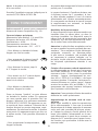
Quando l’etichetta dati tecnici interna alla
cappa mostra il simbolo , l’apparecchio
è in classe II°, quindi nonnecessita di colle-
gamento a terra.
Quando l’etichetta dati tecnici interna alla
cappa nonmostra il simbolo , l’apparec-
chio è in classe I°, quindi necessita di colle-
gamento a terra.
Nell’operazione di collegamento elettrico as-
sicurarsi che la presa di corrente sia munita di
collegamento a terra e vericare che i valori
di tensione corrispondano con quelli indicati
nella targhetta all’interno dell’apparecchio.
Prima di procedere a qualsiasi operazione di
pulizia o manutenzione è necessario togliere
l’apparecchio dalla rete.
Se l’apparecchio non è provvisto di cavo essi-
bile non separabile e di spina, o di altro dispo-
sitivo che assicuri la omnipolare disinserzione
6
SISTEMAD’USO
I modelli SLT950 EM, SLT951 EM, SLT952
EM, SLT958 EM, SLT953 EM, SLT950.1 EM e
SLT951.1 EM (External Motor) possono esse-
re utilizzati solo se abbinati a motori dello
stesso produttore.
I modelli SLT950.1, SLT951.1 e SLT958.1
sono dotati di motore a bordo.
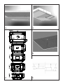
APERTURA PANNELLI
Nei modelli SLT950 EM, SLT951 EM, SLT953
EM, SLT958 EM, SLT950.1, SLT951.1,
SLT950.1 EM, SLT958.1 e SLT951.1 EM è
possibile aprire i pannelli in acciaio di coper-
tura dei ltri antigrasso tirando leggermente
un lato del pannello come indicato in g. 3
Nel modello SLT952 per aprire i pannelli oc-
corre premere gli appositi agganci posti late-
ralmente al pannello, come indicato in gura
11, ruotando il pannello verso il basso.
Per raggiungere l’apertura totale dei pannel-
li occorre sganciare le catene di sicurezza,
agendo mediante gli appositi moschettoni.
Per un adeguato funzionamento si consiglia
di installare il prodotto ad una distanza dal
livello del pavimento di 2000 - 2100 mm.
Prima di procedere nell’installazione dell’ap-
parecchio vericare che tutti i componenti
non siano danneggiati, in caso contrario con-
tattare il rivenditore e non proseguire con
l’installazione.
dalla rete, con una distanza di apertura dei
contatti di almeno 3 mm, allora tali dispositivi
di separazione dalla rete devono essere pre-
visti nell’istallazione ssa.
Se l’apparecchio è provvisto di cavo alimen-
tazione e di spina, deve essere posto in modo
che la spina sia accessibile.
Evitarel’usodimaterialichecausanoam-
mate (ambè) nelle immediate vicinanze
dell’apparecchio. Nel caso di fritture fare
particolarmente attenzione al pericolo di
incendio che costituiscono olio e grassi.
Particolarmente pericoloso per la sua in-
ammabilità è l’oliogià usato. Nonusare
griglie elettriche scoperte. Per evitare un
possibilerischiodiincendioattenersialle
istruzioni indicate per la pulizia dei ltri
antigrassoelarimozionedieventualide-
positidigrassosull’apparecchio.

Inoltreleggereattentamentetutteleistru-
zionidiseguitoriportate.
- Utilizzare un tubo di evacuazione aria che
abbia la lunghezza massima non superiore a
5 metri.
- Limitare il numero di curve nella canalizza-
zione poiché ogni curva riduce l’ecienza di
aspirazione equiparata a 1 metro lineare. (Es:
se si utilizzano n°2 curve a 90°, la lunghezza
della canalizzazione non dovrebbe superare i
3 metri di lunghezza).
- Evitare cambiamenti drastici di direzione.
- Utilizzare un condotto con diametro da
150/200mm costante per tutta la lunghezza.
- Utilizzare un condotto di materiale appro-
vato normativamente.
7
INSTALLAZIONE
SLT950 EM – SLT951 EM – SLT952 EM – SLT953
EM - SLT958EM
Realizzare un controsotto con una apertura
delle dimensioni di:
SLT950 EM: 1465x965mm con distanza mi-
nima di 270mm tra sotto e controsotto;
SLT951 EM: 1065x665mm con distanza mi-
nima di 270mm tra sotto e controsotto;
SLT952 EM: 1050x645 mm con distanza mi-
nima di 250mm tra sotto e controsotto;
SLT953 EM: 1065x665mm con distanza mi-
nima di 270mm tra sotto e controsotto;
SLT958 EM: 865mmx405mm con distanza
minima di 270mm tra sotto e controsot-
to.
E’ possibile scegliere il lato della cappa sul
quale far deuire l’aria aspirata.
Dopo aver scelto la posizione migliore, pre-
disporre la canalizzazione; la fornitura in do-
tazione comprende un raccordo uscita aria
del diametro di 150mm da installare all’uscita
prescelta.
Lasciare chiusi i fori di evacuazione non uti-
lizzati.
Disegnare nel sotto solido il perimetro del
foro di alloggio della cappa a cielo in base al
modello prescelto (Dis. 1); eettuare n° 4 fori
al sotto rispettando le dimensioni riportate
nel dis. 2; inserire nei fori i tasselli metrici
forniti in dotazione.
Aprire i pannelli inox, come descritto nel ca-
pitolo SISTEMA D’USO e rimuovere i ltri an-
tigrasso per evitare eventuali danni e permet-
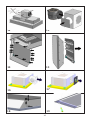
tere l’installazione (Dis.3 ); avvitare le barre
lettate in dotazione nei tasselli (dis.4);le
barre lettate sono lunghe 250 mm e per-
mettono l’installazione della cappa a cielo ad
una distanza dal sotto solido compresa tra
270 mm e 370 mm (Dis. 5); in caso di in-
stallazioni più ampie tra la cappa a cielo e il
sotto occorre munirsi di barre lettate più
lunghe. Eettuare il collegamento elettrico e
collegare il tubo di evacuazione
dell’aria; inserire la cappa a cielo nella nic-
chia facendo entrare le barre lettate nei fori
(Dis.6), il bordo esterno della cappa a cielo
deve coincidere perfettamente con il contro-
sotto.
Inserire nelle barre lettate i piastrini forniti
in dotazione e i dadi facendo attenzione
nel tirarli adeguatamente (dis. 7); riposizio-
nare in sede i ltri antigrasso e i pannelli di
copertura dei ltri antigrasso.

SLT950 – SLT951 – SLT952 – SLT953 CON
MOTORE A BORDO
I modelli con motore a bordo prevedono lo
stesso criterio di installazione della versione
con motore remoto (EM), con alcune dieren-
ze.
In caso di utilizzo del gruppo aspirante con
portata pari a 1000m3/h occorre rispetta-
re una distanza tra sotto e controsotto
pari almeno a 410mm per i modelli SLT950,
SLT951 e SLT953. Il modello SLT952 richiede
una distanza tra sotto e controsotto pari
almeno a 450mm.
In dotazione al gruppo aspirante sono fornite
delle barre lettate lunghe 400 mm.
In caso di utilizzo del gruppo aspirante con
portata pari a 1500m3/h occorre rispetta-
re una distanza tra sotto e controsotto
pari almeno a 470mm per i modelli SLT950,
SLT951 e SLT953.
Il modello SLT952 richiede una distanza tra
sotto e controsotto pari almeno a 520mm.
In dotazione al gruppo aspirante sono fornite
delle barre lettate lunghe 400 mm.
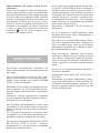
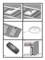
Rimuovere il tappo di chiusura nella parte su-
periore e posizionarvi il motore di aspirazio-
ne (vedi dis.12).
Collegare il cavo elettrico del motore al-
l’apposito connettore presente nella cappa,
orientare la angia uscita aria nella direzione
preferita e ssare il motore alla carcassa uti-
lizzando le viti rimosse in precedenza.
Nel caso sia necessario orientare l’uscita aria
verso l’alto, occorre rimuovere il tappo di
chiusura indicato nel dis. 13. Rimuovere le
viti di ssaggio del motore, estrarlo, ruotar-
lo, inserirlo nel foro di uscita appena aperto
e ssarlo con le viti rimosse in precedenza.
Il foro non utilizzato deve essere chiuso con
l’apposito tappo.
Tenuto conto di questi aspetti, procedere
nell’installazione come indicato nella versio-
ne motore remoto.
8
SLT950.1–SLT951.1-SLT958.1(motore
abordo)
Realizzare un controsotto con una apertura
delle dimensioni di:
SLT950.1 : 1465x965mm con distanza mini-
ma di 330mm tra sotto e controsotto;
SLT951.1 : 1065x665mm con distanza mini-
ma di 330mm tra sotto e controsotto;
SLT958.1 : 865x405mm con distanza minima
di 330mm tra sotto e controsotto
E’ possibile scegliere il lato della cappa dal
quale far deuire l’aria agendo come segue.
Rimuovere le otto viti di ssaggio del gruppo
aspirante, indicate in g. 16, estrarre il grup-
po aspirante sconnettendo il connettore elet-
trico, rimuovere la copertura del foro uscita
aria che si intende utilizzare e posizionarvi
il gruppo aspirante. Ripristinare il collega-
mento elettrico e ssare con le viti rimosse in
precedenza. Ripristinare la copertura nel foro
uscita aria non utilizzato.
Proseguire nell’installazione come indica-
to per la versione SLT950 EM, SLT951 EM e
SLT958 EM.
SLT950.1EM–SLT951.1EM(motorere-
moto)
Realizzare un controsotto con una apertura
delle dimensioni di:
SLT950.1 : 1465x965mm con distanza mini-
ma di 330mm tra sotto e controsotto;
SLT951.1 : 1065x665mm con distanza mini-
ma di 330mm tra sotto e controsotto;
E’ possibile scegliere il lato della cappa dal
quale far deuire l’aria agendo come segue.
Rimuovere le otto viti di ssaggio della angia
uscita aria, indicate in g. 17, quindi posizio-
narla nel lato preferito dove precedentemente
è stata rimossa la copertura.
Ripristinare la copertura nel foro uscita aria
non utilizzato.
Proseguire nell’installazione come indicato
per la versione SLT950 EM e SLT951 EM

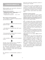
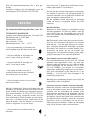
Radiocomando per il comando a distanza di
cappe aspiranti (g. 10).
Caratteristichetecniche:
- Alimentazione a pila alkalina: 12V mod 23°
- Frequenza di lavoro : 433.92 MHz
- Consumo max. : 25 mA
- Temperatura d’esercizio : - 20 + 55°C
Descrizionedifunzionamento:
- Per accendere o spegnere la cappa premere
una sola volta il tasto:
- Per aumentare la velocità no alla 4a (max)
premere il tasto :
- Per diminuire la velocità no alla 2a pre-
mere il tasto:
- Per tornare alla 1 a velocità da una superio-
re premere due volte il tasto:
- Per accendere e spegnere le luci premere
il tasto:
Al primo tocco del tasto luce le lampade si
accendono alla massima potenza.
SLT950 SLT951 SLT953: Mantenendo premu-
to il tasto, la luce diminuisce di intensità per
poi aumentare continuamente. Lasciando il
tasto, la luminosità rimane impostata. Toc-
cando nuovamente il tasto luce è possibile
spegnere le lampade.
Per impostare il temporizzatore premere il
tasto:
9
FUNZIONAMENTO
Alla prima accensione mantenere premuto il
tasto luce per 5 secondi.
Il led più a destra inizierà a lampeggiare (ogni
5 secondi), la cappa rimane accesa per un
tempo di 10 min alla velocità selezionata per
poi spegnersi automaticamente. Aumentando
o diminuendo la velocità mentre il tempo-
rizzatore è attivo, quest’ultimo viene disabi-
litato.
Modalitàdifunzionamento:
Nel caso siano installati due sistemi cappa-
radiocomando nello stesso locale o nelle im-
mediate vicinanze i sistemi avendo lo stesso
codice di trasmissione potrebbero essere in-
uenzati quindi è necessario cambiare il co-
dice di un solo radiocomando.
ATT.: La batteria deve essere sostituita ogni
anno per garantire la portata ottimale del tra-
smettitore, per sostituire la batteria scarica
rimuovere il coperchio di plastica, togliere la
batteria in uso e inserirne una nuova rispet-
tando la polarità indicata nel contenitore. La
batteria usata deve essere smaltita negli ap-
positi contenitori.
Il prodotto è dotato di un dispositivo elettro-
nico che permette lo spegnimento automati-
co dopo quattro ore di funzionamento dal-
l’ultima operazione eseguita.
Generazione di un nuovo codice di tra-
smissione:
Il radiocomando viene fornito dalla fabbrica
con dei codici predeniti. Se si desidera una
nuova generazione di codici, occorre ese-
guire la seguente procedura: Premere con-
temporaneamente i tasti UP (+), STOP (0/1)
e DOWN (-) in modo continuo per 2 secondi,
nello stesso tempo si avrà l’accensione dei
led, succes-sivamente premere i tasti UP (+)
e DOWN (-), 3 lampeggi dei led indicheran-
no che l’operazione è stata completata. ATT:
questa operazione cancella in maniera deni-
tiva i codici preesistenti.

MANUTENZIONE
Un’accurata manutenzione garantisce un
buon funzionamento ed un buon rendimento
nel tempo.
Una cura particolare va rivolta ai ltri anti-
grasso, per rimuovere il ltro antigrasso pro-
cedere come indicato nel capitolo SISTEMA
D’USO, in base al modello.
Rimuovere il ltro antigrasso agendo sull’ap-
posita maniglia. Per il ripristino del ltro an-
tigrasso dopo la pulizia eseguire l’operazione
inversa.
Attenzione, quando riagganciate il pannello
inox di copertura del ltro antigrasso fare at-
tenzione che sia ben ssato.
Per la pulizia dell’apparecchio stesso viene
consigliato l’uso di acqua tiepida e detersivo
neutro, evitando l’uso di prodotti contenenti
abrasivi.
Per la pulizia di apparecchi in acciaio viene
consigliato l’uso di prodotti specializzati, se-
guendo le istruzioni indicate sul prodotto.
Per sostituire la lampada, (SLT950 EM, SLT951
EM, SLT950.1, SLT951.1, SLT953 ) slare la
lampada (dis. 9) e sostituire con una lampada
delle stesse caratteristiche.
10
Per la sostituzione delle lampade uorescen-
ti (SLT952 e SLT952EM) occorre scollegare il
prodotto dalla rete elettrica quindi, aprire il
panello interessato come indicato nel capito-
lo sistema d’uso. Rimuovere le viti perimetrali
indicate dal dis.14; estrarre il supporto del-
le lampade uorescenti (dis. 15), procedere
nella sostituzione utilizzando una lampada
delle stesse caratteristiche.
Ripristinare il pannello e le viti rimosse in
precedenza.
Per la sostituzione dell’alimentatore delle
lampade uorescenti agire analogamente a
come descritto sopra.
Nel caso in cui i pannelli della cappa SLT952,
non siano perfettamente piani e allineati tra
loro è possibile agire sulle viti di ssaggio
dell’aggancio pannello per allinearli e ripor-
tarli perfettamente in piano.
Dopo aver aperto i pannelli, vedi istruzioni
precedenti, allentare la vite indicata in gura
18 e alzare o abbassare l’aggancio del pan-
nello in maniera da allineare il pannello con
l’altro e portarlo in posizione perfettamente
piana.
Serrare la vite precedentemente allentata e
chiudere il pannello.
Sostituzione della barra LED (SLT958 EM -
SLT958.1).
Utilizzando un utensile appropriato, rimuo-
vere la barra LED dalla sua sede (vedi Fig.19),
scollegarla elettronicamente mediante l’ap-
posito connettore quindi sostituirla con una
di pari caratteristiche.
Apprendimento del nuovo codice di tra-
smissione:
Dopo aver cambiato il codice di trasmissio-
ne nel radiocomando, occorre far apprendere
alla centrale elettronica della cappa aspirante
il nuovo codice nel seguente modo: premere
il tasto d’emergenza (visibile dopo l’apertura
del pannello frontale) per due volte conse-
cutive in modo da togliere alimentazione al
prodotto e ripristinarla, da questo momento
ci sono 15 secondi di tempo per premere il
tasto luce per far si che la cappa si sin-
cronizzi con il nuovo codice.

CONTENTS
Warnings
Uses
Installation
Working
Maintenance
11
GB

WARNINGS
The appliance is not intended foruse by
youngchildrenorinrmpersonswithout
supervision.Youngchildrenshouldbesu-
pervised to ensurethey do notplay with
theappliance.
The air sucked can’t be conveyed throu-
gh or into a duct used to let out fumes
fromappliancesfedbyenergyotherthan
electricpower(eg.centralizedheating,ra-
diators,water-heaters,etc.).
Toevacuatethe air outlet, pleasecomply
withthepertainingrulesgivenbycompe-
tentauthorities.
Provide the room with an adequate aeration
when a cooker hood and appliances fed by
energy other than electric power (gas-, oil-,
or coal- stoves, etc.) are used simultaneously.
The cooker hood, when evacuating the sucked
air, could generate a negative pressure in the
room- which can’t exceed the limit of 0.04
mbar, in order to avoid the suck of exhausts
deriving from the heat-source. Therefore the
room should be provided with air-intakes to
allow a costant ow of fresh air.
If the rating lable in the cooker-hood shows
the symbol , the appliance is built in class
II° and it does not need any earth connec-
tion.
If the rating lable in the cooker-hood does
not show the symbol , the appliance is
built in class I° and it needs the earth con-
nection.
When performing the electrical connections
on the appliance, please make sure that the
current-tap is provided with earth connection
and that voltage values correspond to those
indicated on the label placed inside the ap-
pliance itself.
Before carrying out any cleaning or maintai-
ning operations, the appliance needs to be
removed from the electric grid.
If the appliance is not provided with a non-
separable exible cable and plug, or with
12
another device ensuring omnipolar discon-
nections from the grid, with an opening di-
stance between the contacts of at least 3 mm,
then such disconnecting devices must be
supplied within the xed installation.
If the appliance is endowed with a supply cord
and a plug, the appliance has to be put in a
place where the plug can be reached easily.
Theuseofmaterialswhichcanburstinto
amesshould be avoidedin closeproxi-
mityoftheappliance.Whenfrying,please
payparticularattentiontoreriskdueto
oilgrease.Beinghighlyinammable,fried
oilisespeciallydangerous.Donotuseun-
covered electric grills. In order to avoid
possiblererisk,allinstructionsforgrea-
se-ltercleaningandforremovingeven-
tualgreasedepositsshouldbestrictlyfol-
lowed.
USES
SLT950 EM, SLT951 EM, SLT952 EM, SLT958
EM, SLT953 EM, SLT950.1 and SLT951-1 EM
(External Motor) models can be used only if
connected with external motors manufactu-
red by the same producer.
SLT950.1, SLT951.1 and SLT958.1 models
are equipped with internal motor.
PANELSOPENING
In SLT950 EM, SLT951 EM, SLT953 EM, SLT958
EM, SLT950.1, SLT951.1, SLT950.1, SLT958.1
EM and SLT951.1 EM models it is possible to
open the steel panels, which cover the grease
lters, by slightly pulling on a side of the pa-
nel itself, as shown in Fig. 3.
In SLT952 model, to open the panels you
need to push the appropriate hooks placed
on the sides of the panel , as shown in Fig. 11
and then rotating the panel downwards.
To achieve the complete opening of panels,
you need to release the safety chains, by
using the appropriate spring catches.

13
For proper working, it is recommended to in-
stall the appliance at a distance of 2000
- 2100 mm from the oor.
Before starting the appliance installation,
please check that all components are not da-
maged,
in such a case contact your retailer and do not
carry out installation.
Furthermore, please read carefully all of the
following installation instructions.
- Use an exhausting pipe whose maximum
length does not exceed 5 meters.
- Limit the no. of elbows in the piping, since
each elbow reduces the air capacity
of 1 linear meter. (Ex.: if you use no. 2 x 90 °
elbows, the length of piping must not exceed
3 meters).
- Avoid abrupt direction changes.
- Use a 150/200 mm constant diameter pipe
for the whole length.
- Use piping approved by standards in force.
INSTALLATION
SLT950 EM – SLT951 EM-SLT 952 EM – SLT953
EM - SLT958 EM.
Fit a false ceiling with an opening of the fol-
lowing sizes:
SLT950 EM: 1465x965 mm with a minimum
distance of 270 mm between the ceiling and
the false ceiling;
SLT951 EM: 1065x665 mm with a minimum
distance of 270 mm between the ceiling and
the false ceiling.
SLT952 EM: 1050x645 mm with a minimum
distance of 250 mm between the ceiling and
the false ceiling;
SLT953 EM: 1065x665 mm with a minimum
distance of 270 mm between the ceiling and
the false ceiling.
SLT958 EM: 865x405 mm with a minimum
distance of 270 mm between the ceiling and
the false ceiling.
It is possible to select the side of the hood
where the air suctioned can be discharged.
After having chosen the most suitable posi-
tion, prepare the ducting: an air outlet con-
nection piece, with a diameter of 150 mm to
be installed in the side selected, is provided
with the appliance.
Leave any unused exhaust outlets closed.
Draw the outline of the hole to house the cei-
ling-mounted hood on the solid ceiling (Fig.
1), according to the model chosen; make 4
holes in the ceiling according to the dimen-
sions shown in (Fig. 2); place the metric plugs
provided in the holes.
Open the stainless steel panels, following
the instructions mentioned in the USES sec-
tion, and remove the grease lters in order
to avoid damaging them in any way and too
allow installation (Fig. 3); screw the threa-
ded bars provided into the plugs (Fig.4); the
threaded bars are 250 mm long and serve to
install the ceiling-mounted hood at a distan-
ce from the solid ceiling of between 270 mm
and 370 mm (Fig. 5); in case of a larger gap
between the hood and the ceiling, you need
to use longer threaded bars.

14
Make the electrical connections and connect
the air outlet pipe; place the ceiling-mounted
hood into the niche, by inserting the threaded
bars into the holes (Fig.6); the outer edge of
the hood needs to be perfectly ush with the
false ceiling. Insert the plates and nuts pro-
vided into the threaded bars, making sure to
tighten them securely (Fig. 7); ret the grease
lters and lter cover panels.
SLT950 – SLT951 - SLT 952 – SLT953 WITH
INTERNAL MOTOR
With Internal motor models, the same instal-
lation procedure as for the external motor
version (EM) can be followed, but with some
dierences.
If the appliance is equipped with a 1000m3/h
air capacity suctioning unit, a minimum di-
stance of at least 410mm between the ceiling
and the false ceiling needs to be maintained
with SLT950, SLT951 and SLT953 models.
The SLT952 model requires a minimum di-
stance of at least 450mm between the ceiling
and the false ceiling.
Threaded bars of the length of 400mm are
supplied with the suctioning unit.
If the appliance is equipped with a 1500m3/h
air capacity suctioning unit, a minimum di-
stance of at least 470mm between the ceiling
and the false ceiling needs to be maintained
with SLT950, SLT951 and SLT953 models.
The SLT952 model requires a minimum di-
stance of at least 520mm between the ceiling
and the false ceiling.
Threaded bars of the length of 400mm are
supplied with the suctioning unit.
Remove the plug in the upper part of the
appliance and t the suctioning unit. (see
g.12).
Connect the motor electric cable to the suita-
ble connector found inside the cooker hood ,
orient the air out-let ange towards the de-
sired direction and x the motor to the coo-
ker hood body by using the screws previously
removed.
If it is necessary to orient the air out-let
upwards, please remove the plug shown in
g. 13.
Remove the motor xing screws ,pull the mo-
tor out, rotate it and then insert it in the out-
let hole just opened and x it by using the
screws previously removed.
Unused holes must be closed with the suita-
ble plug.
Carry out the installation as shown for the
external motor version, but taking into ac-
count the details above.
SLT950.1– SLT951.1 -SLT958.1(internal
motor)
Fit a false ceiling with an opening that has the
following dimensions:
SLT950.1: 1465x965 mm with a minimum
distance of 330 mm between the ceiling and
the false ceiling;
SLT951.1: 1065x665 mm with a minimum
distance of 330 mm between the ceiling and
the false ceiling
SLT958.1: 865x405 mm with a minimum di-
stance of 330 mm between the ceiling and
the false ceiling
It is possible to select the side of the cooker
hood where the air suctioned can be dischar-
ged, as follows:
Remove the eight xing screws of the suc-
tioning unit shown in g. 16, pull the suc-
tioning unit out by disconnecting the electric
connector , remove the cover of the air out-
let hole you want to use and place the suc-
tioning unit . Restore the electric connec-
tion and secure the suctioning unit with the
screws previously removed . Ret the cover
on the unused air out-let hole.
Carry out the installation following the pro-
cedure shown for SLT950 EM, SLT951 EM and
SLT958 EM models.
SLT950.1EM–SLT951.1EMWITHEXTER-
NALMOTOR
Fit a false ceiling with an opening that has the
following dimensions:
SLT950.1: 1465x965 mm with a minimum
distance of 330 mm between the ceiling and
the false ceiling;
SLT951.1: 1065x665 mm with a minimum
distance of 330 mm between the ceiling and

15
WORKING
6 - channel radio control for cooker hood re-
mote (g. 10).
Technicaldata:
Alkaline battery powered: 12v mod. 23A
Operating frequency: 433.92 Mhz
Combinations: 4096
Max. consumption: 25mA
Operating temperature: -20° : +55°C
- To light the cooker hood on or to
light it o press the button:
- To increase the speed up to the
fourth one press the button:
- To reduce the speed up to the
second one press the button:
- To go from a high speed back to
the rst one press twice the button:
- To give power to the lights or to
shut them down press the button:
The “light” switch can turn the lights on and
o. after the rst touch of the light switch
the lamps turn on at the maximum power.
SLT950 SLT951 SLT953: Keeping the switch
pressed the intensity of the light decreases
and then increases continuously. Leaving the
switch the brightness remains set up. Tou-
ching again the light switch it is possible to
turn the lamps o.
- To set the timer up press the
button:
At rst ignition, keep pressed the lighting
button for 5 seconds
The LED on the right side will start to ash
(every 5 seconds), the hood will work for 10
minutes at the selected speed and then it li-
ghts automatically o.
the false ceiling.
It is possible to select the side of the cooker
hood where the air suctioned can be dischar-
ged, as follows:
Remove the eight xing screws of the air-ou-
tlet ange shown in g. 17, and place the
suctioning unit on the desired side where the
cover was previously removed.
Ret the cover on the unused air out-let
hole.
Carry out the installation following the pro-
cedure shown for SLT950 EM and SLT951
EM models.

Remove the grease lter by pulling its han-
dle.
To reinsert the grease lter after the cleaning,
just perform the opposite operation.
Attention: after refastening the stainless steel
panel make sure that it is properly xed.
Tocleantheapplianceitself tepid water and
neutral detergents are recommended, while
abrasive products must be avoided.
For steel appliances specialized detergen-
ts are recommended (please follow the in-
structions mentioned on the product itself to
obtain the desired results).
To replace the lamp, (SLT950 EM- SLT951
EM , SLT950.1, SLT953 ) remove the lamp
(Fig. 9) and replace it with a lamp of the same
kind.
To replace the uorescent lamps (SLT952
and SLT952EM) you need to disconnect the
appliance from the electrical network, then
open the panel following the instructions gi-
ven in the ‘USES’ section.
Remove the perimeter screws shown in g.
14; pull the uorescent lamps support out
(g.15), and replace the old lamp with a new
one of the same kind.
Ret the panel and the screws previously re-
moved.
To replace the uorescent lamps ballast plea-
se follow the steps described above.
If the panels of the hood SLT952 are out of
line and not perfectly at, it is possible to re-
gulate the screws xing the panel, in order to
align them and make them at again.
After you have opened the panels, according
to the preceding instructions, unscrew the
screw you can see on picture 18 and lift up
or down the panel in order to align it with the
other and make them perfectly at.
Tighten the screw you had loosen and close
the panel.
SubstitutionoftheLEDbar:
Using an appropriate tool, remove the LED
bar from its seat (refer to Fig. 19), disconnect
it electronically using the appropriate con-
nector then substitute it with a LED bar with
same characteristics.
16
If the client increases or reduces the speed
while the timer is on, this is automatically
stopped.
Standardconguration
If two cookerhoods-radiocontrol system are
installed in the same room or in the immediate
vicinity, each system may aect the operation
of the other, due to the fact that they have the
same code. Therefore it will be necessary to
change the code of one of the radio controls.
Warning:
The battery should be replaced eve-
ry yearto guarantee theoptimal rangeof
thetransmitter. Toreplacethe exhausted
battery,taketheplasticlido,removethe
batteryandreplaceitwithanewone,ob-
servingthecorrectbatterypolarities.Used
batteries should be discarded in special
collectionbins.
Generatinganewtransmissioncode
The radiocontrol is supplied by the manufac-
turer with default codes stored. If you want to
create a new set of codes, proceed as follows:
press and hold the UP, STOP and DOWN but-
tons simultaneously for 2 seconds. Afterthe
LEDS light up, press the UP and DOWN button
swithin 5 seconds. The LEDS will ash 3 times
to indicate that the process is completed.
WARNING: This procedure deletes all pre-
viously stored codes.
Learningthenewtransmissioncode
After changing the transmission code on the
radio control, the cooker hood electronic con-
trol unit must be made to set the new code
as follows: press the main Power O button
on the cookerhood (g. 8) and then restore
power to the electronic control unit. Within
the next 15 seconds, press the Light button.
This will ensure the control unit is synchroni-
zed with the new code.
MAINTENANCE
An accurate maintenance guarantees good
functioning and long-lasting performance.
A special care must be paid with grease l-
ters: to remove the grease lter please follow
the instructions given in the ‘USES’ section ,
according to the model chosen.

INDEX
Attention
Versiondel’appareil
Installation
Fonctionnement
Entretien
17
F

18
Si votre appareil n’a pas pas de câble exible
qui ne peut pas être séparé, ni de prise ou bien
d’autre dispositif qui garantisse le débranche-
ment de tous les pôles du réseau,avec une
distance d’ouverture entre les contacts d’au
moins 3mm., ces dispositif de séparation du
réseau doivent alors être prévus dans l’instal-
lation xe.
Si l’appareille xé est pourvu du câble de l’ali-
mentation et une che, l’appareille doit être
placé de manière que la che soit facilement
accessible.
*Evitezd’utiliserdesmatériauxquicausent
desambéesàproximitédel’appareil.Dans
lecas de fritures,faitestoutparticulière-
ment attention au danger d’incendie que
représententleshuilesetlescorpsgras.
Acausedesoninammabilitél’huileusa-
géeestparticulièrementdangereuse.N’uti-
lisezpasdegrillesélectriquesdécouvertes.
Pouréviterdesrisquesd’incendiepossibles
suivezlesinstructionsdonnèesconcernant
lenettoyagedesltresanti-graissesetsur
lafaçond’enleverdesdépotséventuelsde
graissesurlappareil.
ATTENTION
*Lesenfants,lespersonnesdépendantesou
handicapéenepeuventutiliserl’appareilque
siellessontsouslasurveillanced’adultes.
*L’airaspirénedoitpasêtrecanalisédans
unconduitquiestutilisépourévacuerles
fumées produites par des appareils ali-
mentés par des sources d’énergie autres
que l’énergie électrique (installations de
chauagecentral,radiateurs,chaue-eau,
etc.).
* Pour évacuer l’air qui doit être éliminé
respectez les prescriptions des autorités
compétentes.
* Prévoyez une aération de la pièce adéquate
quand une hotte et des appareils alimentés
par une énergie autre que l,énergie électri-
que (poêle à gaz, à charbon, etc.) sont uti-
lisés en même temps. En eet, en évacuant
l’air, la hotte pourrait créer une dépression
dans la pièce. La pression négative de la pièce
ne doit pas dépasser 0,04 mbar, évitant ainsi
que la source de chaleurs provoque un appel
des gaz qui doivent être évaqués. Il est donc
nécessaire d’équiper la pièce de prises d’air
alimentant un ux d’air frais constant.
Quandl’ètiquettedescaractéristiqueste-
chniques,quisetrouvedanslahottemon-
trelesymbole,l’appareilestenclasse
II°,parconséquentiln’apasbesoindeau-
cuneconnexionàlaterre.
Quandl’ètiquettedescaractéristiqueste-
chniques, qui se trouve dans la hotte ne
montrepaslesymbole,l’appareilest
enclasseI°,parconséquentilabesoinde
laconnexionàlaterre.
* L’ors du raccordement électrique assurez-
vous que la prise de courant soit munie de
mise à la terre; vériez aussi que les valeurs
de tension correspondent à celles qui sont
indiquées sur la plaque des caractéristiques
de l’appareil, qui se trouve à l’intérieur de
celui-ci.
*Avant de procéder à une opération d’entre-
tien ou de nettoyage quelconque, il faut dé-
brancher l’appareil.
VERSIONSDEL’APPAREIL
Les modèles SLT950 EM, SLT951 EM, SLT952
EM, SLT958 EM, SLT953 EM et SLT950.1 EM
et SLT951.1 EM External Motor) peuvent être
utilisés seulement s’ils sont couplés à des
moteurs externes du même producteur.
Les modèles SLT950.1, SLT951.1 et SLT958.1
sont équipés avec un moteur à bord.
OUVERTUREDESPANNEAUX
Pour les modèles SLT950 EM, SLT951 EM,
SLT953 EM, SL958 EM, SLT950.1, SLT951.1,
SLT950.1 EM, SL958.1 et SLT951.1 EM il est
possible d’ouvrir les panneaux en acier de
couverture des ltres anti-graisse en tirant
légèrement un côté du panneau comme indi-
qué dans la g. 3.
Pour ouvrir les panneaux du modèle SLT952
appuyer sur les crochets qui se trouvent sur
les côtés du panneau, comme indiqué dans la
g. 11, en tournant le panneau vers le bas.

INSTALLATION
SLT950 EM – SLT951 EM – SLT952 EM –
SLT953EM-SLT958EM.
Réaliser un faux plafond avec une ouverture
ayant les dimensions suivantes:
SLT950EM: 1465x965mm avec distance mi-
nimum de 270mm entre plafond et faux pla-
fond;
SLT951EM: 1065x665mm avec distance mi-
nimum de 270mm entre plafond et faux pla-
fond;
SLT952 EM: 1050x645 mm avec distance
minimum de 250mm entre plafond et faux
plafond;
SLT953EM: 1065x665mm avec distance mi-
nimum de 270mm entre plafond et faux pla-
fond;
SLT958EM: 865x405mm avec distance mi-
nimum de 270mm entre plafond et faux pla-
fond;
Choisir le côté de la hotte par lequel l’air sera
évacué. Après avoir localisé la bonne solu-
tion, prédisposer le tuyau d’évacuation. La
fourniture en dotation comprend une bride
circulaire 150mm pour la sortie supérieure et
une bride ovale avec un raccord ovale 150mm
en cas de sortie latérale. Veiller à laisser fer-
mé les orices d’évacuation non employés.
Dessiner sur le plafond solide le périmètre du
trou de logement de la hotte selon le modèle
choisi (Des. 1); eectuer n° 4 trous sur le pla-
fond en respectant les dimensions reportées
dans le dessin 2; introduire dans les trous des
goujons métriques fournis en dotation; ouvrir
les panneaux inox et retirer les ltres anti-
graisse pour éviter les dommages et permet-
tre l’installation (Des. 3); visser les barres -
letées fournies en dotation dans les goujons
(Des. 4); les barres letées ont une longueur
de 250 mm et elles permettent l’installation
de la hotte à une distance du plafond solide
comprise entre 270 mm et 370 mm (Des. 5);
en cas d’installations plus vastes entre la hot-
te et le plafond, il est nécessaire de se munir
de barres letées plus longues.
Pour obtenir la pleine ouverture des pan-
neaux, libérer les chaînes de sécurité en
détachant les mousquetons.
Pour un fonctionnement correcte on conseil
d’installer la hotte à une distance du niveau
du sol de 2000 - 2100 mm.
Avant de commencer l’installation de l’ap-
pareil vérier si tous les composants ne sont
pas endommagés; dans le cas contraire, con-
tacter le revendeur et ne pas poursuivre l’in-
stallation.
Enoutre,lireattentivementtouteslesin-
structionssuivantes:
- Utiliser un tuyau d’évacuation d’une lon-
gueur maximale de 5 mètres.
- Limiter le nombre des coudes de la canali-
sation, puisque chaque coude réduit le ren-
dement d’aspiration d’un mètre linéaire. (Par
exemple: si on utilise 2 coudes de 90° la lon-
gueur de la canalisation ne doit pas dépasser
les 3 mètres).
- Éviter des drastiques changements de di-
rection.
- Utiliser un conduit d’un diamètre de 150
/200mm pour toute la longueur.
- Utiliser un conduit en matériel approuvé par
la réglementation.
19

Eectuer le branchement électrique et relier le
tube d’évacuation de l’air; introduire la hotte
dans la niche en faisant entrer les barres -
letées dans les trous (Des. 6), le bord externe
de la hotte doit coïncider parfaitement avec
le faux-plafond. Introduire dans les barres
letées les plaquettes fournies en dotation et
les écrous en faisant attention de la tirer cor-
rectement (Des. 7); ensuite xer la hotte avec
les vis fournies en dotation.
SLT950–SLT951–SLT952–SLT953AVEC
MOTEURABORD
Les modèles avec moteur à bord compren-
nent les mêmes critères d’installation de la
version External Motor (EM), avec quelques
diérences.
Lorsque vous utilisez l’unité d’aspiration avec
une capacité égale à 1000m3 / h, il faut res-
pecter une distance entre le plafond et le faux
plafond d’au moins 410mm pour les modèles
SLT950, SLT951 et SLT953. Le modèle SLT952
nécessite d’une distance entre le plafond et
le faux plafond d’au moins 450mm.
Le groupe aspirant est doté de barres letées
longues 400mm.
Lorsque vous utilisez l’unité d’aspiration avec
une capacité égale à 1500m3 / h, il faut res-
pecter une distance entre le plafond et le faux
plafond d’au moins 470mm pour les modèles
SLT950, SLT951 et SLT953. Le modèle SLT952
nécessite d’une distance entre le plafond et
le faux plafond d’au moins 520mm.
Le groupe aspirant est doté de barres letées
longues 400mm.
Enlever le bouchon de fermeture qui se trou-
ve dans la partie supérieure e positionner le
moteur d’aspiration (voir dessin 12). Brancher
le câble électrique du moteur dans le con-
necteur approprié qui se trouve à l’intérieure
de la hotte, orienter le collet sortie air dans la
direction préférée et xer le moteur à la car-
casse en utilisant les vis précédemment enle-
vés. Dans le cas où il est nécessaire d’orien-
ter la sortie air vers le haut, il faut enlever le
bouchon de fermeture indiqué dans le dessin
13. Enlever les vis de serrage du moteur ; puis
il faut le retirer, le rouler et l’insérer dans le
trou eectué et ensuite le xer avec les vis
précédemment enlevés. Fermer le trou non
utilisé avec le bouchon approprié.
20
Tenant compte de ces aspects, procédez l’in-
stallation comme indiqué pour la version Ex-
ternal Motor.
SLT950.1 – SLT951.1 - 958.1 (moteur à
bord)
Réaliser un faux plafond avec une ouverture
ayant les dimensions suivantes:
SLT950.1: 1465x965mm avec distance mini-
mum de 330mm entre plafond et faux pla-
fond;
SLT951.1: 1065x665mm avec distance mini-
mum de 330mm entre plafond et faux plafond;
SLT958.1: 865x405mm avec distance minimum
de 330mm entre plafond et faux plafond;
Choisir le côté de la hotte par lequel l’air sera
évacué.
Enlever les huit vis de serrage du groupe
d’aspiration, comme indiqué dans la g. 16,
retirer le groupe d’aspiration en débranchant
le connecteur électrique, enlever le bouchon de
fermeture de la sortie d’air que vous voulez uti-
liser et y placer le groupe d’aspiration. Rétablir
le branchement électrique et serrer avec les vis
précédemment enlevées. Mettre le bouchon sur
le trou pour la sortie d’air non utilisé.
Procéder l’installation comme indiqué pour la
version SLT950 EM, SLT951 EM et SLT98 EM.
SLT950.1 EM – SLT951.1 EM (External
Motor)
Réaliser un faux plafond avec une ouverture
ayant les dimensions suivantes:
SLT950.1: 1465x965mm avec distance mini-
mum de 330mm entre plafond et faux pla-
fond;
SLT951.1: 1065x665mm avec distance mini-
mum de 330mm entre plafond et faux plafond.
Choisir le côté de la hotte par lequel l’air sera
évacué.
Enlever les huit vis de serrage du collet sortie
d’air, comme indiqué dans la g. 17, puis po-
sitionner-le dans le côté choisi où précédem-
ment vous avez enlever le bouchon.
La pagina si sta caricando...
La pagina si sta caricando...
La pagina si sta caricando...
La pagina si sta caricando...
La pagina si sta caricando...
La pagina si sta caricando...
La pagina si sta caricando...
La pagina si sta caricando...
La pagina si sta caricando...
La pagina si sta caricando...
La pagina si sta caricando...
La pagina si sta caricando...
La pagina si sta caricando...
La pagina si sta caricando...
La pagina si sta caricando...
La pagina si sta caricando...
La pagina si sta caricando...
La pagina si sta caricando...
La pagina si sta caricando...
La pagina si sta caricando...
La pagina si sta caricando...
La pagina si sta caricando...
La pagina si sta caricando...
La pagina si sta caricando...
-
 1
1
-
 2
2
-
 3
3
-
 4
4
-
 5
5
-
 6
6
-
 7
7
-
 8
8
-
 9
9
-
 10
10
-
 11
11
-
 12
12
-
 13
13
-
 14
14
-
 15
15
-
 16
16
-
 17
17
-
 18
18
-
 19
19
-
 20
20
-
 21
21
-
 22
22
-
 23
23
-
 24
24
-
 25
25
-
 26
26
-
 27
27
-
 28
28
-
 29
29
-
 30
30
-
 31
31
-
 32
32
-
 33
33
-
 34
34
-
 35
35
-
 36
36
-
 37
37
-
 38
38
-
 39
39
-
 40
40
-
 41
41
-
 42
42
-
 43
43
-
 44
44


Sirius Satellite Radio EMSLT958 EM Manuale utente
- Tipo
- Manuale utente
in altre lingue
- English: Sirius Satellite Radio EMSLT958 EM User manual
- français: Sirius Satellite Radio EMSLT958 EM Manuel utilisateur
- español: Sirius Satellite Radio EMSLT958 EM Manual de usuario
- Deutsch: Sirius Satellite Radio EMSLT958 EM Benutzerhandbuch
- Nederlands: Sirius Satellite Radio EMSLT958 EM Handleiding
Altri documenti
-
ELICA FEEL EUPHORIA F/80 Guida utente
-
Groupe Brandt DHG799X Manuale del proprietario
-
 De Dietrich DHL7173X Informazioni importanti
-
-
 De Dietrich DHL7173X-01 Manuale del proprietario
-
Falmec Lumen island Istruzioni per l'uso
-
-
-
-

