
7366546 (Rev. B 1/24/18)
Systems tested and certified by the Water Quality
Association against CSA B483.1.
Systems tested and certified by NSF International
against NSF/ANSI Standard 44
for hardness reduction and efficiency,
and certified to NSF/ANSI Standard 372.
Installation and Operation Manual
If you have any questions or concerns when
installing, operating or maintaining your water
softener, call our toll free number:
1-800-972-0135
or visit www.northstarwater.com
When you call, please be prepared to provide
the model and serial number of your product,
found on the rating decal, located on the back
of the controller top cover.
Manufactured and warranted by
North Star Water Treatment Systems
1890 Woodlane Drive
Woodbury, MN 55125
Designed, Engineered &
Assembled in the U.S.A.
How to install, operate
and maintain your Demand
Controlled Water Softener
Models NST30ED
NST45ED1
NST70ED1

2
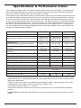
TABLE OF CONTENTS
Page
S
pecifications & Performance Claims . . . . . . . . . . . . . . . . . . . . . . . . . . . . . . . . . . . . . . . . . . . . . . . . . . . . . . . . . . . . 3
Dimensions . . . . . . . . . . . . . . . . . . . . . . . . . . . . . . . . . . . . . . . . . . . . . . . . . . . . . . . . . . . . . . . . . . . . . . . . . . . . . . . . 4
Before You Start . . . . . . . . . . . . . . . . . . . . . . . . . . . . . . . . . . . . . . . . . . . . . . . . . . . . . . . . . . . . . . . . . . . . . . . . . . . . 4
Installation Requirements . . . . . . . . . . . . . . . . . . . . . . . . . . . . . . . . . . . . . . . . . . . . . . . . . . . . . . . . . . . . . . . . . . . . . 5
T
ypical Installation Illustrations . . . . . . . . . . . . . . . . . . . . . . . . . . . . . . . . . . . . . . . . . . . . . . . . . . . . . . . . . . . . . . . . . 6
Installation Instructions . . . . . . . . . . . . . . . . . . . . . . . . . . . . . . . . . . . . . . . . . . . . . . . . . . . . . . . . . . . . . . . . . . . . . 7-10
P
rogramming the Electronic Controller . . . . . . . . . . . . . . . . . . . . . . . . . . . . . . . . . . . . . . . . . . . . . . . . . . . . . . . 11-12
Controller Features / Options . . . . . . . . . . . . . . . . . . . . . . . . . . . . . . . . . . . . . . . . . . . . . . . . . . . . . . . . . . . . . . . . . 13
Wiring Schematic . . . . . . . . . . . . . . . . . . . . . . . . . . . . . . . . . . . . . . . . . . . . . . . . . . . . . . . . . . . . . . . . . . . . . . . . . . 13
Routine Maintenance . . . . . . . . . . . . . . . . . . . . . . . . . . . . . . . . . . . . . . . . . . . . . . . . . . . . . . . . . . . . . . . . . . . . . . . 14
Troubleshooting . . . . . . . . . . . . . . . . . . . . . . . . . . . . . . . . . . . . . . . . . . . . . . . . . . . . . . . . . . . . . . . . . . . . . . . . . 15-17
Exploded View & Parts List . . . . . . . . . . . . . . . . . . . . . . . . . . . . . . . . . . . . . . . . . . . . . . . . . . . . . . . . . . . . . . . . 18-23
WATER SOFTENER WARRANTY
Warrantor: North Star Water Treatment Systems, 1890 Woodlane Drive, Woodbury, MN 55125
Warrantor guarantees, to the original owner, that:
One Year Full Warranty:
● For a period of one (1) year from the date of purchase, all parts will be free from defects in materials and workman-
ship and will perform their normal functions.
Limited Warranties:
● For a period of ten (10) years from the date of purchase, the salt storage tank and fiberglass mineral tank will not rust,
corrode, leak, burst, or in any other manner, fail to perform their proper functions.
● For a period of three (3) years from the date of purchase, the electronic control board and valve body will be free of
defects in materials and workmanship and will perform their normal functions.
If, during such respective period, a part proves to be defective, Warrantor will ship a replacement part directly to your
home, without charge.
General Provisions
Damage to any part of this water softener because of misuse, misapplication, neglect, alteration, accident, installation or
operation contrary to our printed instructions, or damage caused by any unusual force of nature such as, but not limited to,
freezing, flood, hurricane, tornado, or earthquake is not covered by this warranty. In all such cases, regular parts and serv-
ice charges will apply.
We assume no warranty liability in connection with this water softener other than specified herein. This warranty is in lieu
of all other warranties, expressed or implied, including warranties of fitness for a particular purpose. We do not authorize
any person or representative to assume for us any other obligations on the sale of this water softener.
Should a defect or malfunction occur, contact your contractor. If you are unable to contact your contractor, return the part,
freight prepaid, directly to the factory at the address below. Enclose with the part a full description of the problem, with
your name, full address, date purchased, model and serial numbers, and selling contractor's name and address. We will
repair or replace the part and return it to you at no cost if our repair department determines it to be defective under the
terms of the warranty.
This warranty gives you specific legal rights and you may have other rights which vary from state to state.
This water softener is manufactured by
North Star Water Treatment Systems, 1890 Woodlane Drive, Woodbury, MN 55125
Customer Information Telephone No. 1-800-972-0135
Inspect Shipment
The parts required to assemble and install the water
softener are included with the unit. Thoroughly check
the water softener for possible shipping damage and
parts loss. Also inspect and note any damage to the
shipping carton.
Remove and discard (or recycle) all packing materials.
To avoid loss of small parts, we suggest you keep the
small parts in the parts bag until you are ready to use
them.

3
Specifications & Performance Claims
Model NST30ED NST45ED1 NST70ED1
Model Code SR30 SR45 SR70
Rated Softening Capacity (Grains @ Salt Dose)
11,800 @ 2.3 lbs.
25,300 @ 7.4 lbs.
30,200 @ 12.5 lbs.
13,300 @ 2.6 lbs.
35,700 @ 9.9 lbs.
45,300 @ 17.2 lbs.
20,800 @ 4.1 lbs.
55,100 @ 15.2 lbs.
70,000 @ 26.4 lbs.
Rated Efficiency
(Grains/Pound of Salt @ Minimum Salt Dose)
5,090 @ 2.3 lbs. 5,070 @ 2.6 lbs. 5,080 @ 4.1 lbs.
Water Used During Regeneration @ Minimum
Salt Dose
3.2 gal. /
1,000 grains
4.1 gal. /
1,000 grains
4.3 gal. /
1,000 grains
Total Water Used Per Regeneration @ Maximum
Salt Dose
39.5 gallons 56.0 gallons 101 gallons
Rated Service Flow Rate 7.3 gpm 10.0 gpm 13.5 gpm
Amount of High Capacity Ion Exchange Resin 0.78 cu. ft. 1.26 cu. ft. 1.94 cu. ft.
Pressure Drop at Rated Service Flow 15.0 psig 11.2 psig 15.0 psig
Intermittent Flow rate @ 15 psi* 7.3 gpm 12.1 gpm 13.5 gpm
Water Supply Max. Hardness 90 gpg 120 gpg 120 gpg
Water Supply Max. Clear Water Iron 8 ppm** 12 ppm** 19 ppm**
Water Pressure Limits (minimum / maximum) 20 - 125 psi***
Water Temperature Limits (minimum / maximum) 40 - 120 °F
Minimum Water Supply Flow Rate 3 gpm
Maximum Drain Flow Rate 2.0 gpm 2.0 gpm 3.0 gpm
T
hese models are efficiency rated. The efficiency rating is valid only at the minimum salt dose. The softeners have
a demand initiated regeneration (D.I.R.) feature that complies with specific performance specifications intended to
m
inimize the amount of regenerant brine and water used in its operation.
T
hese softeners have a rated softener efficiency of not less than 3,350 grains of total hardness exchange per pound
of salt (based on sodium chloride) and shall not deliver more salt than its listed rating or be operated at a sustained
m
aximum service flow rate greater than their listed rating. These softeners have been proven to deliver soft water
for at least ten continuous minutes at the rated service flow rate. The rated salt efficiency is measured by laboratory
tests described in NSF/ANSI Standard 44. These tests represent the maximum possible efficiency that the system
can achieve. Operational efficiency is the actual efficiency after the system has been installed. It is typically less
than the rated efficiency, due to individual application factors including water hardness, water usage, and other con-
taminants that reduce a softener's capacity.
*Intermittent flow rate does not represent the maximum service flow rate used for determining the softeners’ rated
capacity and efficiency. Continuous operation at flow rates greater than the service flow rate may affect capacity
and efficiency performance.
**Capacity to reduce clear water iron is substantiated by laboratory test data. State of Wisconsin requires addi-
tional treatment if water supply contains clear water iron exceeding 5 ppm.
***Canada working pressure limits: 1.4 - 7.0 kg/cm
2
.
These systems conform to NSF/ANSI 44 for the specific performance claims as verified and substantiated by
test data.
Variable Salt Dose: The salt dose is selected by the electronic controls at regeneration time based on the amount
needed.

4
18"
DIA.
39"
C
14"
3-3/4"
OUTLET
INLET
INLET -
OUTLET
A
B
FIG. 1
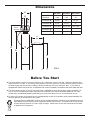
Dimensions
INLET
OUTLET
INLET -
OUTLET
18”
dia.
39”
A
B
C
D
= The water softener requires a minimum water flow of 3 gallons per minute at the inlet. Maximum allowable inlet
water pressure is 125 psi. If your house water pressure is over the maximum, install a pressure reducing valve in
the water supply pipe to the system (Adding a pressure reducing valve may reduce the flow). If your home is
equipped with a back flow preventer, an expansion tank must be installed in accordance with local codes and laws.
= The water softener works on 24V DC electrical power, supplied by a direct plug-in power supply (included). Be
sure to use the included power supply and plug it into a nominal 120V, 60 Hz household outlet that is in a dry
location only, grounded and properly protected by an overcurrent device such as a circuit breaker or fuse.
= Do not use this system to treat water that is microbiologically unsafe or of unknown quality without adequate dis-
infection upstream or downstream of the system.
European Directive 2002/96/EC requires all electrical and electronic equipment to be disposed of accord-
ing to Waste Electrical and Electronic Equipment (WEEE) requirements. This directive or similar laws are
in place nationally and can vary from region to region. Please refer to your state and local laws for prop-
er disposal of this equipment.
Before You Start
NST30ED NST45ED1 NST70ED1
N
ominal Resin
Tank Size
8
” dia.
x 40”
1
0” dia.
x 40”
1
2” dia.
54”
Dimension A
4
8-3/4” 50” 65-3/4”
Dimension B
41-1/4” 41-1/4” 57”
Dimension C
8-1/4” dia. 10-1/2” dia. 12-1/4” dia.
Dimension D
3-3/8” 3-3/4” 3-3/4”
Dimension E
11-1/2” 14” 14”
E

5
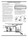
THE PROPER ORDER TO INSTALL WATER TREATMENT EQUIPMENT
FIG. 3
Pressure
Tank
City Water Supply
Well Water Supply
Well
Pump
OR
Optional
Sediment
Filter
Water
Heater
Water
Softener
Untreated Water to
Outside Faucets
Hot Water
to House
Cold Water
to House
LOCATION REQUIREMENTS
Consider all of the following when selecting an installa-
tion location for the water softener.
= Do not locate the water softener where freezing
temperatures occur. Do not attempt to treat water
over 120ºF. Freezing temperatures or hot water
damage voids the warranty.
= To condition all water in the home, install the water
softener close to the water supply inlet, and
upstream of all other plumbing connections, except
outside water pipes. Outside faucets should remain
on hard water to avoid wasting conditioned water
and salt.
= A nearby drain is needed to carry away regenera-
tion discharge (drain) water. Use a floor drain,
laundry tub, sump, standpipe, or other options
(check your local codes). See "Air Gap
Requirements" and "Valve Drain Requirements"
sections.
= The water softener works on 24V DC electrical
power, supplied by a direct plug-in power supply
(included). Provide nearby a 120V, 60 Hz electrical
outlet, in accordance with national and local codes.
= Always install the water softener between the water
inlet and water heater. Any other installed water
conditioning equipment should be installed between
the water inlet and water softener (See Figure 3
below).
= Avoid installing in direct sunlight. Excessive sun
heat may cause distortion or other damage to non-
metallic parts.
Installation Requirements
PLUMBING CODES
All plumbing must be completed in accordance with
national, state and local plumbing codes.
LAUNDRY TUBSTANDPIPE
1-1/2”
air gap
FLOOR DRAIN
In the state of Massachusetts: The Commonwealth
of Massachusetts plumbing code 248-CMR shall
be adhered to. A licensed plumber shall be used
for this installation.
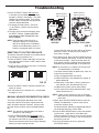
AIR GAP REQUIREMENTS
A drain is needed for regeneration water (See Figure
2). A floor drain, close to the water softener, is pre-
ferred. A laundry tub, standpipe, etc. are other drain
options. Secure valve drain hose in place. Leave an
air gap of 1-1/2” between the end of the hose and the
drain. This gap is needed to prevent backflow of
sewer water into the water softener. Do not put the
end of the drain hose into the drain.
FIG. 2
1-1/2”
air gap
Drain
Hose
Drain
Hose
1-1/2”
air gap
Drain
Hose

6
FIG. 4
S
oft
Water
H
ard
Water
Hard Water to
outside faucets
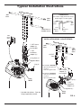
CROSSOVER
U
se if water supply flows from the left.
Include single or 3-valve bypass.
MA
I
N
W
A
T
ER
PI
PE
Hard
Water
Soft
Water
To
Softener
Inlet
From
Softener
Outlet
1” NPT Sweat
Adaptor (2)
not included
1” NPT
Installation
Adaptor (2) *
O-ring Seal (2) *
Bypass Valve *
Clip (4) *
* Included with softener. Pipe and
fittings supplied by installer.
Valve
INLET
Valve
INLET
1” NPT
Installation
Adaptor (2) *
O-ring Seal (2) *
Clip (2) *
1” NPT Sweat
Adaptor (2)
not included
INLET
Valve
OUTLET
Valve
BYPASS
Valve
MA
IN
WA
T
E
R
P
IPE
INSTALLATION USING 3-VALVE BYPASS
For soft water SERVICE:
- Open the inlet and out-
let valves
- Close the bypass valve
For hard water BYPASS:
- Close the inlet and out-
let valves
- Open the bypass valve
Soft
Water
Hard
Water
120V,
60 Hz
Outlet
Typical Installation Illustrations

7
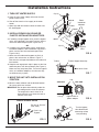
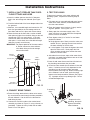
1. TURN OFF WATER SUPPLY
a. Close the main water supply valve near the well
pump or water meter.
b. Shut off the electric or fuel supply to the water
heater.
c. Open high and low faucets to drain all water from
the house pipes.
2. INSTALL BYPASS VALVE AND/OR
PLASTIC INSTALLATION ADAPTORS:
a. If installing a single bypass valve, push the bypass
valve, with lubricated o-ring seals in place, into the
valve inlet and outlet ports (See Figures 4 & 6).
- OR -
b. If installing a 3-valve bypass system, slide plastic
installation adaptors, with lubricated o-ring seals in
place, into the valve inlet and outlet ports (See
Figures 4 & 6).
c. Make sure the turbine and support are firmly in
place in the valve outlet, as shown in Figure 7.
Blow into the valve port and observe the turbine for
free rotation.
d. Snap the two large plastic clips in place on the inlet
and outlet ports, from the top, down (See Figure 8).
Make sure they snap into place. Pull on the bypass
valve, or installation adaptors, to make sure they
are held securely in place.
3. MOVE THE UNIT INTO INSTALLATION
POSITION
a. Move the water softener into the desired location.
Set it on a solid, level surface.
IMPORTANT: Do not place shims directly under the
salt storage tank to level the softener.
The weight of the tank, when full of
water and salt, may cause the tank to
fracture at the shim.
FIG. 8
O-ring
Clip
Bypass valve or
plastic adaptor
END VIEWSIDE VIEW
FIG. 7
Turbine
Turbine Support Assembly
Valve Outlet
FIG. 9
Turn the bypass
valve downward if
connecting to floor
level plumbing
INLET
OUTLET
FIG. 5
SINGLE BYPASS VALVE
Pull out for “Service”
(Soft water)
Push in for
“Bypass”
FIG. 6
INLET
OUTLET
Clip (2)
Bypass
Valve
Plastic
i
nstallation
adaptors
Clip (2)
Turbine
Support
Installation Instructions

8
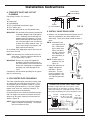
Installation Instructions
4. COMPLETE INLET AND OUTLET
PLUMBING
P
ipe fittings must be 3/4” minimum.
Use:
=
Copper pipe
= Threaded pipe
= PEX (Crosslinked Polyethylene) pipe
= CPVC plastic pipe
= Other pipe approved for use with potable water
IMPORTANT: Do not solder with plumbing attached to
installation adaptors and single bypass
valve. Soldering heat will damage the
adaptors and valve.Measure, cut, and
loosely assemble pipe and fittings from
the main water pipe to the inlet and out-
let ports of the water softener valve. Be
sure to keep fittings fully together, and
pipes squared and straight.
Be sure hard water supply pipe goes to the water sof-
tener valve inlet side.
NOTE: Inlet and outlet are marked on the water sof-
tener valve. Trace the water flow direction to
be sure hard water is to inlet.
IMPORTANT: Be sure to fit, align and support all
plumbing to prevent putting stress on
the water softener valve inlet and outlet.
Stress from misaligned or unsupported
plumbing may cause damage to the
valve.
Complete the inlet and outlet plumbing for the type of
pipe you will be using.
5. COLD WATER PIPE GROUNDING
The house cold water pipe (metal only) is often used
as a ground for the house electrical system, The 3-
valve bypass type of installation, shown in Figure 4,
will maintain ground continuity. If you use a plastic
bypass valve at the unit, continuity is broken. To
restore the ground, do the following:
Purchase and securely install two grounding clamps
and a #4 copper wire across the location where the
softener will be, tightly clamping it at both ends, as
shown in Figure 10.
NOTE: Check local plumbing and electrical codes for
proper installation of grounding. The installa-
tion must conform to them.
6. INSTALL VALVE DRAIN HOSE
a. Measure, cut to needed length and connect the 3/8"
drain line (provided) to the water softener valve
drain fitting. Use a hose clamp to hold the hose in
place.
NOTE: Avoid drain hose
runs longer than 30
feet. Avoid elevat-
ing the hose more
than 8 feet above
the floor. Make the
valve drain line as
short and direct as
possible.
NOTE: If codes require a
rigid drain line see
Figure 12.
b. Route the drain hose or
copper tubing to the
floor drain. Secure
drain hose. This will
prevent “whipping'' dur-
ing regenerations. See
“Air Gap Requirements"
section.
FIG. 11
Drain Fitting
on valve
Valve
Drain
Hose
1-1/2”
Air Gap
To
Floor
Drain
CONNECTING A RIGID VALVE DRAIN TUBE:
To adapt a copper drain tube to the softener, cut the
barbed end from the drain fitting, as shown. Obtain a
compression fitting (1/4” female pipe thread x 1/2” O.D.
tube) and needed tubing from your local hardware store.
FIG. 12
1/4” NPT
Threads
Clip
Compression Fitting,
1/4” NPT x 1/2” O.D.
tube (not provided)
Cut barbs from drain fitting (pull
clip and remove elbow from valve)
1/2” O.D.
copper tube
(not provided)
FIG. 10
Ground Wire
(not included)
Clamp
(2 - not included)

9
Nozzle/
Venturi
Ferrule Nut
Brine
Valve
Tubing
Brinewell
Grommet
Hose
Adaptor
To
Drain
Overflow
Drain Hose
Brinewell
Cover
Brine TankResin Tank
FIG. 13
8. CONNECT BRINE TUBING
a. Route the tubing attached to the brine valve assem-
bly out of the brine tank through the hole provided in
the tank sidewall. Use the slot in the brinewell to
hold tubing in place.
b. Connect the end of this tube to the nozzle/venturi
assembly, as shown in Figure 13, using a ferrule nut
(provided). Tighten the nut by hand, then an addi-
tional 1/4 turn with pliers.
9. TEST FOR LEAKS
To prevent air pressure in the water softener and
p
lumbing system, complete the following steps in
order:
a. Fully open two or more softened cold water faucets
close to the water softener, located downstream
from the water softener.
b. Place the bypass valve (single or 3 valve) into the
"bypass" position. See Figures 4 & 5.
c. Slowly open the main water supply valve. Run
water until there is a steady flow from the opened
faucets, with no air bubbles.
d. Place bypass valve(s) in "service" or soft water
position as follows:
= Single bypass valve: Slowly move the valve stem
toward "service," pausing several times to allow
the water softener to fill with water.
= 3 valve bypass: Fully close the bypass valve and
open the outlet valve. Slowly open the inlet
valve, pausing several times to allow the water
softener to fill with water.
e. After about three minutes, open a hot water faucet
until there is a steady flow and there are no air bub-
bles, then close this faucet.
f. Close all cold water faucets and check for leaks at
the plumbing connections that you made.
g. Check for leaks around clips at softener’s inlet and
outlet. If a leak occurs at a clip, depressurize the
plumbing (turn off the water supply and open
faucets) before removing clip. When removing clips
at the softener’s inlet or outlet, push the single
bypass valve body toward the softener (See Figure
14). Improper removal may damage clips. Do not
reinstall damaged clips.
7. INSTALL SALT STORAGE TANK OVER-
FLOW FITTINGS AND HOSE
a. Insert the rubber grommet into the 3/4” diameter
hole in the salt storage tank sidewall (See Figure
13).
b. Push the barbed end of the hose adaptor elbow into
the grommet.
c. Measure, cut to needed length and connect the 3/8"
drain line (provided) to the salt storage tank over-
flow elbow and secure in place with a hose clamp.
d. Route the hose to the floor drain, or other suitable
drain point no higher than the drain fitting on the salt
storage tank (This is a gravity drain). If the tank
overfills with water, the excess water flows to the
drain point. Cut the drain line to the desired length
and route it neatly out of the way.
IMPORTANT: For proper operation of the water soften-
er, do not connect the water softener
valve drain tubing to the salt storage
tank overflow hose.
FIG. 14
...depressurize the
plumbing, then push
Bypass Valve body
toward softener
If removing
clips...
Installation Instructions

10
Installation Instructions
10. ADD WATER AND SALT TO THE SALT
STORAGE TANK
a. Using a container, add about three gallons of clean
water into the salt storage tank.
b
. Add salt to the storage tank. Use nugget, pellet or
coarse solar salts with less than 1% impurities.
11. PLUG IN THE POWER SUPPLY
During installation, the water softener wiring may be
moved or jostled from place. Be sure all leadwire con-
nectors are secure on the back of the electronic board
and be sure all wiring is away from the valve gear and
motor area, which rotates during regenerations.
a. Plug the power supply into an electrical outlet that is
not controlled by a switch.
NOTE: The water heater is filled with hard water and,
as hot water is used, it will refill with condi-
tioned water. In a few days, the hot water will
be fully conditioned. To have fully conditioned
hot water immediately, wait until the initial
recharge is over. Then, drain the water heater
(following instructions for water heater) until
water runs cold.
12. PROGRAM THE CONTROLLER
a. Complete the Programming Steps on the next two
pages.
13. SANITIZE THE WATER SOFTENER /
SANITIZE AFTER SERVICE
Care is taken at the factory to keep your unit clean and
sanitary. Materials used to make the unit will not infect
or contaminate your water supply, and will not cause
bacteria to form or grow. However, during shipping,
storage, installation and operation, bacteria could get
into the unit. For this reason, sanitizing as follows is
suggested* when installing.
a. Slide open the salt lid, remove the brinewell cover
and pour about 3 oz. (6 tablespoons) of household
bleach into the softener brinewell. Replace the
brinewell cover.
b Make sure the bypass valve(s) is in the “service”
(open) position.
c Start a recharge: Press the RECHARGE button and
hold for 3 seconds, until “Recharge Now” begins to
flash in the display. This recharge draws the sanitiz-
ing bleach into and through the water softener. Any
air remaining in the unit is purged to the drain.
d. After the recharge has completed, fully open a cold
water faucet, downstream from the softener, and
allow 50 gallons of water to pass through the sys-
tem. This should take at least 20 minutes. Close
the faucet.
*Recommended by the Water Quality Association. On some
water supplies, the unit may need periodic disinfecting.
14. RESTART THE WATER HEATER
a. Turn on the electricity or fuel supply to the water
heater and relight the pilot, if applicable.
NOTE: The water heater is filled with hard water and,
as hot water is used, it refills with conditioned
water. In a few days, the hot water will be fully
conditioned. To have fully conditioned hot
water immediately, wait until the initial recharge
(previous step) is over. Then, drain the water
heater (following instructions for water heater)
until water runs cold.
Questions? Call Toll Free 1-800-972-0135 or visit www.northstarwater.com
When you call, please be prepared to provide the model and serial number,
found on the rating decal, located on back of the controller top cover.

11
Programming the Electronic Controller
CONTROLLER SETTINGS REQUIRED
upon installation, and after an extended power outage.
When the power supply is plugged into the electrical
outlet, a model code (see table on page 3) and a soft-
ware version number (example: J3.9), are briefly
shown in the display. Then the words “PRESENT
TIME” appear and 12:00 PM begins to flash.
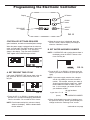
A. SET PRESENT TIME OF DAY
If the words “PRESENT TIME" do not show in the dis-
play, press the SELECT button several times until
they do.
FIG. 16
FIG. 17
2. When the correct time is displayed, press the
SELECT button, and the display will change to
show the “Hardness” screen.
B. SET WATER HARDNESS NUMBER
NOTE: If “HARDNESS” and a number do not show in
the display, press the SELECT button a few
times until they do.
1. Press the UP (È) or DOWN (–) buttons to set the
present time. Up moves the display ahead; down
sets the time back. Be sure AM or PM is correct.
NOTE: Press buttons and quickly release to slowly
advance the display. Hold the buttons down
for fast advance.
1. Press the UP (È) or DOWN (–) buttons to set the
value of your water’s hardness in grains per gallon
(gpg).
NOTE: If your water supply contains iron, compen-
sate for it by adding to the water hardness
number. For example, assume your water is
20 gpg hard and contains 2 ppm iron. Add 5
to the hardness number for each 1 ppm of
iron. In this example, you would use 30 for
your hardness number.
20 gpg hardness
2 ppm iron x 5 = 10 +10
(times) 30 HARDNESS NUMBER
2. When finished setting your water’s hardness num-
ber, press the SELECT button, and the display will
change to show the “Recharge Time” screen.
FIG. 18
continued on next page
FIG. 15
UP button
DOWN
button
Display
RECHARGE
button
SELECT
button

12
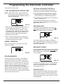
OPTIONAL RECHARGE CONTROLS
S
ometimes a manually initiated regeneration (re -
charge) may be desired or needed. Two examples:
= You have used more water than usual (guests,
extra washing, etc.) and you may run out of soft
water before the next scheduled regeneration.
= You did not refill the storage tank with salt before it
had run completely out.
Use one of the following two features to begin a
regeneration either immediately or at the next preset
regeneration start time:
RECHARGE NOW
To manually start a regeneration cycle, press and
hold the RECHARGE button for a few seconds, until
“RECHARGE NOW” flashes in the display.
The softener begins an immediate regeneration.
When completed (in about two hours), you will have a
new supply of soft water. Once started, you cannot
cancel this regeneration.
RECHARGE TONIGHT
To set a regeneration cycle to begin at the next preset
regeneration time, touch (press, but do not hold) the
RECHARGE button. “RECHARGE TONIGHT” flash-
es in the display.
FIG. 21
A regeneration will begin at the next preset regenera-
tion start time (2:00 AM or as set). If you decide to
cancel this regeneration before it starts, touch the
same button once more.
VACATION NOTE
North Star demand controlled water softeners regen-
erate only while water is being used and softening
capacity must be restored. For this reason, the unit
will not regenerate when you are away from home for
extended periods.
FIG. 22
Programming the Electronic Controller
FIG. 19
FIG. 20
c
ontinued from previous page
1. Press the UP (È) or DOWN (–) buttons to set the
desired regeneration start time in 1 hour incre-
ments. The factory default is 2:00 AM. In most
households this is a good time for regeneration to
start (takes about 2 hours) because water is not
being used. During regeneration hard water is
bypassed to house faucets.
2. When finished setting the desired regeneration
start time, press the SELECT button. The display
then shows the present time of day.
NORMAL OPERATION
During normal operation, the present time of day
shows in the display.
C. SET REGENERATION STARTING TIME
NOTE: If “RECHARGE TIME” and a flashing time
(2:00 AM is the factory default) are not show-
ing in the display, press the SELECT button a
few times until they do.
PROGRAM MEMORY
If electrical power to the softener is interrupted, the
time display is blank, but the electronic controller
keeps correct time for several hours. When power is
restored, you must reset the present time only if the
display is flashing. All other settings are maintained
and never require resetting unless a change is
desired. If the time is flashing after a long power out-
age, the softener continues to work as it should to
provide you with soft water. However, regenerations
may occur at the wrong time of day until you reset the
clock to the correct time of day.

13
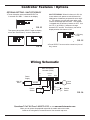
OPTIONAL SETTING: SALT EFFICIENCY
1. To set this option, press and hold SELECT for
3 seconds until “000 - -” shows in the display.
Then press (do not hold) SELECT again to display
one of the “Salt Efficiency” screens shown below.
SALT EFFICIENCY: When this feature is ON, the
w
ater softener will operate at salt efficiencies of
4000 grains of hardness per pound of salt or high-
e
r. The softener may recharge more often using
smaller salt dosage and less water. This softener
is shipped with the efficiency feature set OFF. Use
the UP (È) or DOWN (–) buttons to change
between OFF and ON. An efficiency icon will be
displayed when this feature is ON.
Controller Features / Options
FIG. 23
FIG. 24
2. Press SELECT to return to the normal run (time of
day) screen.
FIG. 25
Efficiency
Icon
Questions? Call Toll Free 1-800-972-0135 or visit www.northstarwater.com
When you call, please be prepared to provide the model and serial number,
found on the rating decal, located on back of the controller top cover.
FIG. 26
NO
Valve
Motor
Position
Switch
NC
Back of Electronic
Controller (PWA)
Pwr.
In
Position/
Turbine
Motor
24V DC
120V AC
60Hz
Power
Supply
C
org
grn
Turbine
Sensor
+5
OUT
GND
Wiring Schematic

14
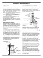
FIG. 27
Broom
Handle
Pencil
Mark
1” - 2”
Salt
Salt Bridge
Water Level
Push tool into
salt bridge to
break
FIG. 28
Cap
O-ring Seal
Screen Support
Screen
Gasket
*Flow Plug (HVDC)
Housing
Ferrule
Nut
Cone Screen
*Flow Plug
*Install with lettered
side up, concave
side down.
CLEANING THE NOZZLE & VENTURI
A clean nozzle & venturi (See Figure 28) is a necessity
for the water softener to work properly. This small
component creates the suction to move brine from the
brine tank, into the resin tank. If it should become
p
lugged with sand, silt, dirt, etc., the water softener will
not work, and hard water will result.
Nozzle & Venturi Disc
IMPORTANT: Be sure small hole in the gasket is cen-
tered directly over the small hole in the nozzle & ven-
turi housing. Be sure the numbers are facing up
Routine Maintenance
ADDING SALT
Lift the salt storage tank cover and check the salt level
frequently. If the water softener uses all the salt
before you refill it, you will experience hard water.
Until you have established a refilling routine, check the
s
alt every two or three weeks. Always add if less than
1/4 full. Be sure the brinewell cover is on.
NOTE: If using potassium chloride (KCl), do not fill the
storage tank more than 1/2 full.
NOTE: In humid areas, it is best to keep the salt stor-
age level lower, and to refill more often to
avoid salt “bridging”.
Recommended Salt: Nugget, pellet or coarse solar
salts with less than 1% impurities.
Salt Not Recommended: Rock salt, high in impurities,
block, granulated, table, ice melting, ice cream making
salts, etc.
BREAKING A SALT BRIDGE
Sometimes, a hard crust or salt “bridge” forms in the
brine tank. It is usually caused by high humidity or the
wrong kind of salt. When the salt “bridges,” an empty
space forms between the water and the salt. Then,
salt will not dissolve in the water to make brine.
Without brine, the resin bed is not recharged and hard
water will result.
If the storage tank is full of salt, it is difficult to tell if
you have a salt bridge. A bridge may be underneath
loose salt. Take a broom handle, or like tool, and hold
it next to the water softener. Measure the distance
from the floor to the rim of the water softener. Then,
gently push the broom handle straight down into the
salt. If a hard object is felt before the pencil mark is
even with the top, it is most likely a salt bridge. Gently
push into the bridge in several places to break it. Do
not use any sharp or pointed objects as you may
puncture the brine tank. Do not try to break the salt
bridge by pounding on the outside of the salt tank.
You may damage the tank.
To get access to the nozzle & venturi, remove the
water softener’s top cover. Put the bypass valve(s)
into the bypass position. Be sure the water softener is
in soft water (service) cycle (no water pressure at noz-
zle & venturi). Then, holding the nozzle & venturi
housing with one hand, un screw the cap. Do not lose
the o-ring seal. Lift out the screen support and screen.
Then, remove the nozzle & venturi disc, gasket and
flow plug(s). Wash the parts in warm, soapy water
and rinse in fresh water. Be sure to clean both the top
and bottom of the nozzle & venturi disc. If needed,
use a small brush to remove iron or dirt. Do not
scratch, misshape, etc., surfaces of the nozzle & ven-
turi.
Gently replace all parts in the correct order. Lubricate
the o-ring seal with silicone grease and locate in place.
Install and tighten the cap by hand, while supporting
the housing. Overtightening may break the cap or
housing. Put the bypass valve(s) into service (soft
water) position.
Recharge the softener to reduce water level in the
tank. This will also assure that the softener is com-
pletely recharged and ready to provide softened water
again. Check the water level in the tank by looking
down the brinewell. If the water level does not drop
after a recharge, the problem has not been resolved.
Call 1-800-972-0135.
Empty Space

15
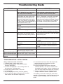
Troubleshooting Guide
P
ROBLEM
C
AUSE
C
ORRECTION
No soft water No salt in the storage tank. Add salt and then initiate a “Recharge Now”.
Salt is “bridged” (a layer of salt in the
salt storage tank has hardened).
Break salt bridge, as described on the previous
page, and then initiate a “Recharge Now”.
If display is blank, power supply may be
unplugged at wall outlet, power cable
leads may be disconnected from the
electronic control board, fuse may be
blown, circuit breaker may be popped,
or power supply may be plugged into a
switched outlet which is “off.”
Check for power loss due to any of these and
correct. When power is restored, if the display
shows the “Present Time” setting screen, it
means time was lost during the outage. Set the
present time. Other settings such as hardness
are retained in memory during a power loss.
Manual bypass valve(s) in bypass
position.
Place bypass valve(s) in service position.
Dirty, plugged or damaged nozzle &
venturi.
Take apart, clean and inspect the nozzle & ven-
turi assembly.
Valve drain hose plugged or restricted. Drain hose must not have any kinks, sharp
bends, or be raised too high above the softener.
Water hard sometimes Bypassed hard water being used dur-
ing recharge, due to present time or
recharge time settings being incorrect.
Check the time displayed. If not correct, refer
to “Set Present Time of Day”. Check the regen-
eration starting time.
Hardness number setting is too low. Referring to “Set Water Hardness Number”,
check the current hardness setting and increase
if needed.
Hot water being used when softener is
recharging.
Avoid using hot water during recharges,
because water heater refills with hard water.
Increase in actual hardness of water
supply.
Have unsoftened water sample tested. Check
the current “Hardness” setting and increase if
needed.
Turbine is not turning freely. Check turbine, as described on the next page.
Motor stalled or clicking Motor malfunction or internal valve
fault causing high torque on motor.
Contact your dealer for service.
Error code Err01, Err02,
Err03 or Err04 displayed.
Fault in wiring harness, connections to
position switch, switch, valve or motor.
Contact your dealer for service.
Error code Err05 dis-
played.
Electronic timer (PWA) malfunction. Contact your dealer for service.
TROUBLESHOOTING - INITIAL CHECKS
Always make these initial checks first:
1. Is display blank? Check power source.
2. Is Error code displayed? If so, go to “Automatic
Electronic Diagnostics.”
3. Is correct time displayed? If not, recharges occur at
the wrong time. Set present time.
4. Is there salt in the brine tank? If not, refill.
5. Is salt “bridged”?
6. Are plumbing bypass valve(s) in service position?
7. Are inlet and outlet pipes connected to the True Blue
water softener inlet and outlet respectively?
8. Is valve drain hose free of kinks and sharp bends,
and not elevated over 8 feet above the floor.
9. Is the brine tube connected?
10. Check the hardness setting (See “Set Water
Hardness Number”). Be sure it is correct for the
household's water supply. Perform a hardness test
on a raw water sample to compare with the setting.
11. Perform a hardness test on a conditioned water
sample to determine whether a problem exists.
If no problem is found after making the initial checks,
proceed to “Troubleshooting - Manual Diagnostics” and
“Manual Advance Recharge Check” on the next two
pages.

16
Troubleshooting
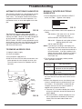
AUTOMATIC ELECTRONIC DIAGNOSTICS
The electronic controller has a self-diagnostic function
for the electrical system (except input power and
water meter). The computer monitors the electronic
components and circuits for correct operation. If a
malfunction occurs, an error code appears in the dis-
play.
FIG. 29
FIG. 30
The chart on the previous page shows the error
codes that could appear, and possible problems indi-
cated by the codes. While an error code is displayed,
all timer buttons are inoperable, except for the
SELECT button. SELECT remains operational so the
service person can make use of the Manually Initiated
Electronic Diagnostics to further isolate the defect,
and check the water meter.
TO REMOVE AN ERROR CODE:
1. Unplug the power supply.
2. Correct the problem.
3. Plug the power supply back in.
4. Wait for at least 8 minutes while the electronic con-
troller operates the valve through an entire cycle.
The error code will return if the problem was not
corrected.
FIG. 31
MANUALLY INITIATED ELECTRONIC
DIAGNOSTICS
1. To enter diagnostics, press and hold the SELECT
button until “000 - -” appears in the display.
2. The first 3 digits indicate water meter operation as
follows:
000 (steady) = Soft water not in use, and no
flow through the meter.
OPEN A NEARBY SOFT WATER FAUCET.
000 to 140* = Repeats for each gallon of water
passing through the meter.
*199 for model NST30ED
NOTE: If you don't get a reading in the display with
faucet open, pull the sensor from the valve out-
let port. Pass a small magnet back and forth in
front of the sensor. If you get a reading in the
display with the magnet, unhook the in and out
plumbing and check the turbine for binding
(See Figure 30).
3. The last 2 digits in the display indicate position
switch operation as follows:
4. Use the RECHARGE button to manually advance
the valve into each cycle and check correct switch
operation.
5. While in this diagnostic screen, the following infor-
mation is available and may be beneficial for vari-
ous reasons. This information is retained by the
computer from the first time electrical power is
applied to the electronic controller.
a. Press the UP (È) button to display the number
of days this electronic control has had electrical
power applied.
b. Press the DOWN (–) button to display the num-
ber of regenerations initiated by this electronic
control since the model code number was
entered.
Correct Switch
Displays
Valve Cycle Status
– –
Valve in service, fill, brining,
backwash or fast rinse position.
– P
Valve rotating from one position
to another.
Motor
Valve
Outlet
Position
Switch
Sensor
Housing
Turbine
Turbine
Support
& Shaft

17
FIG. 33
This check verifies proper operation of the valve
motor, brine tank fill, brine draw, regeneration flow
rates, and other controller functions. Always make
the initial checks, and the manual initiated diagnos-
tics.
NOTE: The electronic control display must show a
steady time (not flashing).
1. Press the RECHARGE button and hold in for 3
seconds. “RECHARGE NOW” begins to flash as
the softener enters the fill cycle of regeneration.
Remove the brinewell cover and, using a flashlight,
observe fill water entering the tank.
MANUAL ADVANCE REGENERATION CHECK
Troubleshooting
6
. Press the SELECT button and hold
i
n for
3 seconds until the model code (see table
on page 3) shows in the display. This code
identifies the softener model. If the wrong
number shows, the softener will operate on
i
ncorrect configuration data.
7. To change the code number - Press UP
(È) or DOWN (–) button until the correct
code shows.
8. To return to the present time display, press
the SELECT button. If the model code
was changed, make all electronic con-
troller settings.
NOTE: If the electronic control is left in a
diagnostic display (or a flashing dis-
play when setting times or hardness),
present time automatically returns if a
button is not pressed within 4 minutes.
3. Press the SELECT button, and the electronic con-
troller will restart.
4. Set the present time, hardness, etc., as described
on pages 11 & 12.
If water does not enter the tank, look for an obstruct-
ed nozzle, venturi, fill flow plug, brine tubing, or
brine valve riser pipe.
2. After observing fill, press the RECHARGE button to
move the softener into brining. A slow flow of water
to the drain will begin. Verify brine draw from the
brine tank by shining a flashlight into the brinewell
and observing a noticeable drop in the liquid level.
NOTE: Be sure water is in contact with the salt, and
not separated by a salt bridge.
If the water softener does not draw brine, check for
(most likely to least likely):
= Dirty or plugged nozzle and venturi.
= Nozzle and venturi not seated on the gasket, or
gasket deformed.
= Restriction in valve drain, causing a back-pres-
sure (bends, kinks, elevated too high, etc.).
= Obstruction in brine valve or brine tubing
= Inner valve failure (obstructed outlet disc, wave
washer deformed, etc.)
NOTE: If water system pressure is low, an elevated
drain hose may cause back pressure, stopping
brine draw.
3. Again, press the RECHARGE button to move the
softener into backwash. Look for a fast flow of
water from the drain hose.
An obstructed flow indicates a plugged top distribu-
tor, backwash flow plug, or drain hose.
4. Press the RECHARGE button to move the softener
into fast rinse. Again look for a fast drain flow.
Allow the softener to rinse for a few minutes to flush
out any brine that may remain in the resin tank from
the brining cycle test.
5. To return the softener to service, press the
RECHARGE button.
FIG. 32
NST45ED1 & NST70ED1
M
OTOR
CAM
Position markers
(valve in service)
Position markers
(valve in service)
CAM
MOTOR
NST30ED
RESETTING TO FACTORY DEFAULTS
To reset the electronic controller to its factory default
for all settings (time, hardness, etc.):
1. Press the SELECT button and hold it until the dis-
play changes twice to show “CODE” and the flash-
ing model code.
2. Press the UP (È) button (a few times, if necessary)
to display a flashing “SoS”.

18
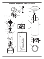
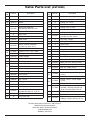
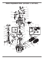
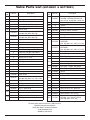
Softener Exploded View (All Models)
Valve Assembly
See Pages 20-23
for parts
5
6
7
8
9
10
11
13
12
4
3
2
18
17
19
27
25
20
21
22
23
26
24
15
16
1
14

19
Key
No.
Part No. Description
1 7
351054
P
ower Supply, 24V DC
2 7309358
R
epl.Electronic Control Board
(PWA)
3
7180291
Faceplate Cover, NST30ED
(also order following decal)
7260554
Faceplate Cover,
NST45ED1 & NST70ED1
(also order following decal)
¢
7267344 Faceplate Decal, NST30ED
7366083
Faceplate Decal
NST45ED1 & NST70ED1
4
7180314 Bottom Cover, NST30ED
7189449
Bottom Cover,
NST45ED1 & NST70ED1
– 7331177
Tank Neck Clamp Kit
(includes Key Nos. 5 & 6)
5
á
Clamp Section (2 req.)
6
á
Retainer Clip (2 req.)
– 7112963
Distributor O-Ring Kit
(includes Key Nos. 7-9)
7
á
O-Ring, 2-7/8” x 3-1/4”
8
á
O-Ring, 13/16” x 1-1/16”
9
á
O-Ring, 2-3/4” x 3”
10 7077870 Top Distributor
11 7105047 Repl. Bottom Distributor
12
7289998
Repl. Resin Tank, 8” x 40”,
NST30ED
7290070
Repl. Resin Tank, 10” x 40”,
NST45ED1
7113074
Repl. Resin Tank, 12” x 54”,
NST70ED1
Key
No.
Part No. Description
1
3
0
502272
R
esin, 53 lbs. (1 cu. ft.)
14
1183000 Tank Foot, 8”, NST30ED
7302039 Tank Foot, 10”, NST45ED1
7339222 Tank Foot, 12”, NST70ED1
15 7180437
Brine Tank Cover
(also order following decal)
– 7270779 Instruction Decal
16 7155115 Cover, Brinewell
17 7109871 Brinewell
– 7331648
Brinewell Mounting Hardware Kit
(includes Key Nos. 18 & 19)
18
á
Wing Nut, 1/4-20
19
á
Screw, 1/4-20 x 5/8”
20 7112612
Repl. Brine Tank
(includes Key Nos. 17-19)
– 7331258
Overflow Hose Adaptor Kit
(includes Key Nos. 21-23)
21
á
Adaptor Elbow
22
á
Grommet
23
á
Hose Clamp
24 7139999 Drain Hose, 20 ft.
25
7310197 Brine Valve Assembly, NST30ED
7310210
Brine Valve Assembly,
NST45ED1 & NST70ED1
26
7113008
Float, Stem & Guide Assembly,
NST30ED
7327568
Float, Stem & Guide Assembly,
NST45ED1 & NST70ED1
27 7248706
Ground Clamp Kit Ù
¢
7366546 Owner’s Manual
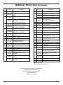
Softener Parts List (All Models)
To order repair parts call toll free 1-800-972-0135.
Manufactured and warranted by
North Star Water Treatment Systems
1890 Woodlane Drive
Woodbury, MN 55125
¢
Not illustrated.
Ù Not included with the system.

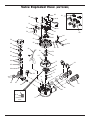
20
Valve Exploded View (NST30ED)
5
0
51
52
54
53
55
56
57
58
59
60
61
62
63
64
65
66
68 67
69
70
71
Wear Strip
Seal
Cross-section
View
74
72
73
75
76
77
78
79
80
81
82
83
84
85
86
87
88
89
90
91
92
93
94
95
91
96
La pagina si sta caricando...
La pagina si sta caricando...
La pagina si sta caricando...
-
 1
1
-
 2
2
-
 3
3
-
 4
4
-
 5
5
-
 6
6
-
 7
7
-
 8
8
-
 9
9
-
 10
10
-
 11
11
-
 12
12
-
 13
13
-
 14
14
-
 15
15
-
 16
16
-
 17
17
-
 18
18
-
 19
19
-
 20
20
-
 21
21
-
 22
22
-
 23
23


North Star NST30ED Istruzioni per l'uso
- Tipo
- Istruzioni per l'uso
in altre lingue
Documenti correlati
Altri documenti
-
Power Fist 8455099 Manuale del proprietario
-
EcoWater eVOLUTION Power 600 Instructions Manual
-
Fleck 4600 Manuale del proprietario
-
Culligan Mark 59 Guida utente
-
 RainSoft HDINSTIUDWS Manuale utente
-
Edgewater Networks Center Console 228 Owner Assistance Manual
-
Rancilio Epoca S1 Use And Maintenance
-
ELEKTRA Professional espresso coffee machines Manuale utente
-
Hendi 299265 Manuale utente
-
Sammic DS-12 Manuale utente
