
1
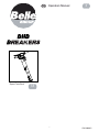
- Spare Parts Book
Operators Manual
GB
4
18
870/90000/2

2
Signed by: Managing Director - On behalf of BELLE GROUP (SHEEN) UK.
Signature: Le Directeur Général - Pour le compte de la SOCIETE BELLE GROUP (SHEEN) UK.
Medido por: Director Gerente - En nombre de BELLE GROUP (SHEEN) UK.
Assinado por: Director-Geral - Em nome de BELLE GROUP (SHEEN) UK.
Getekend door: Algemeen Directeur - Namens BELLE GROUP (SHEEN) UK.
Uunderskrevetaf: Administrerende direktør – På vegne af BELLE GROUP (SHEEN) UK.
PRODUCT TYPE ................. TYPE DE PRODUIT.............. TIPO DE PRODUCTO.......... TIPO DE PRODUCTO .........
MODEL................................. MODELE............................... MODELO .............................. MODELO..............................
SERIAL No........................... N° DE SERIE........................ N° DE SERIE........................ NO. DE SÉRIE .....................
DATE OF MANUFACTURE. DATE DE FABRICATION ..... FECHA DE FABRICACIÓN.. DATA DE FABRIC
SOUND POWER LEVEL NIVEAU DE PUISSANCE NIVEL DE POTENCIA NIVEL DE POTÊNCIA
MEASURED......................... SONORE MESUREE............ ACÚSTICA MEDIDO............ DE SOM MEDIDO................
(GUARANTEED).................. (GARANTIE)......................... (GARANTIZADO)................. (GARANTIDO) .....................
WEIGHT............................... POIDS................................... PESO.................................... PESO ...................................
We, Belle Group Sheen UK, Sheen, Nr. Buxton, Derbyshire, SK17 0EU, GB, hereby certify that if the product described within this certificate is bought from an
authorised Belle Group dealer within the EEC, it conforms to the following EEC directives: 98/37/EC (This directive is a consolidation of the original machinery directive
89/392/EEC), Electromagnetic Compatibility Directive 89/336/EEC (as amended by 92/31/EEC & 93/68 EEC). The low voltage directive 73/23/EEC, BS EN ISO
12100-1:2003 Safety of machinery and associated harmonised standards, where applicable. Noise emissions conform to directive 2000/14/EC Annex VI, for machines
under article 12 the notified body is AV Technology Limited, AVTECH house, Birdhall Lane, Cheadle Heath, Stockport, Cheshire, SK3 0XU, GB.
Noise Technical Files are held at the Belle Group Head Office address which is stated above.
Nous soussignons, Belle Group Sheen UK, Sheen, Nr Buxton, Derbyshire, SK17 0EU, GB, certifions que si le produit décrit dans ce certificat est acheté chez un
distributeur autorisé Belle Group au sein de la CEE, il est conforme aux normes CEE ci-après: 98/37/CE (Cette norme est une codification des normes de la machine
d'origine 89/392/CEE), Norme compatible pour l'électromagnisme 89/336/CEE (modifié par 92/31/CEE et 93/68/CEE). Caractéristiques basse tension 73/23/CEE, BS EN
ISO 12100-1:2003, Norme de sécurité des machines et des critères associés et configurés, si applicable. Les émissions de bruit sont conformes à la directive
2000/14/EC Annexe VI pour machines , article 12, l’objet mentionné est AV Technology Mimited, AVTECH House, Birhall Lane, Cheadle Heath, Stockport, Cheshire,
SK3 0XU, GB.
Les dossiers techniques sur les émissions sonores des machines sont détenus au siège social de BELLE GROUP à l’adresse ci-dessus.
La Sociedad, Belle Group Sheen UK, Sheen, Nr. Buxton, Derbyshire, SK 17 OEU, GB, por el presente documento certifica que si el producto descrito en este
certificado es comprado a un distribuidor autorizado de Belle Group en la CEE, este es conforme a las siguientes directivas: 98/37/CE de la CEE (Esta directiva
consolida la directiva inicial sobre maquinaria 89/392/CEE), Directiva 89/336 CEE sobre Compatibilidad Electromagnética (según enmiendas 92/31/CEE y 93/68 CEE),
Directiva sobre Bajo Voltaje 73/23/CEE, BS EN ISO 12100-1:2003 de Seguridad de Maquinaria y Niveles armonizados estándares asociados donde sean aplicables.
Emisión de Ruídos conforme a la Directiva 2000/14/CE Anexo VI para máquinas bajo artículo 12 la mencionada unidad está AV Technology Limited, AVTECH House,
Birdhall Lane, Cheadle Heath, Stockport, Cheshire, SK3 OXU, GB.
En La Sede Central de Belle Group existen Archivos Técnicos con contenido referente a Niveles de Ruido.
O signatário, Belle Group Sheen UK, Sheen, Nr Buxton, Derbyshire, SK 0EU, GB, pelo presente, declara que se o produto descrito neste certificado foi adquirido a
um distribuidor autorizado do Belle Group em qualquer país da UE, está em conformidade com o estabelecido nas seguintes directivas comunitárias: 98/37/EC (esta
directiva é uma consolidação da directiva de maquinaria original 89/392/EEC), Directiva de Compatibilidade Electromagnética 89/336/EEC (conforme corrigido pelas
92/31/EEC & 93/68 EEC). A directiva de baixa voltagem 73/23/EEC, BS EN ISO 12100-1:2003 Segurança da maquinaria e às normas harmonizadas afins se aplicáveis.
As emissões de ruído respeitam e estão dentro das directivas para máquinas 2000/14/EC Anexo VI, artigo 12, sendo o organismo notificado AV Technology Limited,
AVTECH house, Birdhall Lane, Cheadle Heath, Stockport, Cheshire, SK3 0XU, GB.
A informação técnica sobre níveis sonoros está disponivel na Sede da Belle Group na morada acima mencionada.
Ondergetekende, Belle Group Sheen UK, Sheen, Nr. Buxton, Derbyshire, SK17 OEU, GB, verklaren hierbij dat als het product zoals beschreven in dit certificaat is
gekocht van een erkende Belle Group dealer binnen de EEG, het voldoet aan de volgende EEG richtlijnen: 98/37/EC (Deze richtlijn is een opvolger van de orginele
Machinerichtlijn 89/392/EEG), Electromagnetische Compatability Richtlijn 89/336/EEG ( geamendeerd door 92/31/EEG & 93/68 EEG). De Laagspannings Richtlijn
72/23/EEG, BS EN ISO 12100-1:2003 Veiligheid van Machines en hieraan gekoppelde geharmoniseerde Standaarden, waar deze van toepassing is. Rumoer emissions
passen voor richtlijn EC Zijgebouw VI , voor toestel onder stuk 12 naar de notified troep zit AV Technology Limited, AVTECH house, Birdhall Lane, Cheadle Heath,
Stockport, Cheshire, SK3 OXU, GB
Worden de Technische Dossiers van het lawaai gehouden op het adres van het Hoofdkantoor van de Groep Belle dat hierboven ' wordt verklaard.
Vi, Belle Group Sheen UK, Sheen, Nr. Buxton, Derbyshire, SK17 0EU, GB, erklærer hermed, at hvis det i dette certifikat beskrevne produkt er købt hos en autoriseret
Belle Group forhandler i EU, er det i overensstemmelse med følgende EØF-direktiver: 98/37/EF, 73/23/EØF (som ændret ved 93/68/EØF), 89/336/EØF (som ændret ved
92/31/EØF), 93/68/EØF og tilknyttede, harmoniserede standarder, hvor relevant. Støjniveauet er i overensstemmelse med direktiv 2000/14/EF, bilag VI gældende for
maskiner under paragraf 12. Det bemyndigede organ er AV Technology Limited, AVTECH house, Birdhall Lane, Cheadle Heath, Stockport, Cheshire, SK3 0XU,
Storbritanien.
EC DECLARATION OF CONFORMITY / DECLARATION CE DE CONFORMITE /
DECLARACIÓN DE CONFORMIDAD CE / DECLARAÇÃO CE DE CONFORMIDADE /
EG-VERKLARING VAN OVEREENSTEMMING / EF
OVERENSSTEMMELSESERKLÆRING
Ray Neilson
PRODUCTTYPE .................. PRODUKTTYPE...................
MODEL................................. MODEL .................................
SERIENUMMER................... SERIENR. .............................
FABRICAGEDATUM............ FREMSTILLINGSDATO .......
GEMETEN LYDEFFEKTNIVEAU
GELUIDSSTERKTENIVEAU MÅLT....................................
(GEGARANDEERD) ............ (GARANTERET)...................
GEWICHT............................. VÆGT...................................
GB
F
E
P
NL
DK

3
Unterzeichnet vo: Generaldirektor – Im auftrag von BELLE GROUP (SHEEN) UK.
Firmato da: Amministratore Delegato – Per conto di BELLE GROUP (SHEEN) UK.
Undertecknat: V.D. – På vägnar av BELLE GROUP (SHEEN) UK.
Signatur: Managing Director - På vegne av SOCIETE BELLE GROUP (SHEEN) UK.
Allekirjoitus: Toimitusjohtaja - BELLE GROUP (SHEEN) UK: n puolesta.
Podpisa³: Dyrektor Zarządzający – w imieniu BELLE GROUP (SHEEN) UK
PRODUKTTYP..................... TIPO PRODOTTO ................ PRODUKTTYP..................... PRODUKTTYP.....................
MODELL .............................. MODELLO ............................ MODELL............................... MODELL ..............................
SERIENNR........................... SERIE N°.............................. SERIE NR. ........................... SERIE NR. ..........................
HERSTELLUNGSDATU ...... DATA DI FABBRICAZIONE.. TILLVERKNINGSDATUM..... PRODUKSJONSDATO........
SCHALLLEISTUNGSPEGEL LIVELLO POTENZA LJUDSTYRKA LYDKRAFTNIVÅ
GEMESSEN......................... SONORA MISURATA ........... UPPMÄTT............................. MÅLT ...................................
(GARANTIERT).................... (GARANTITA)....................... (GARANTERAD).................. (GARANTERT) ....................
GEWICHT............................. PESO .................................... VIKT...................................... VEKT....................................
Wir, Belle Group Sheen UK, Sheen, Nr. Buxton, Derbyshire, SK17 0EU, Großbritannien, bestätigen hiermit, dass das in diesem Zertifikat beschriebene Produkt,
wenn es von einem autorisierten Belle Group Händler innerhalb der europäischen Gemeinschaft gekauft wurde, folgenden EG-Richtlinien entspricht: 98/37/EG, 73/23/EG
(geändert durch 93/68/EG), 89/336/EG (geändert durch 92/31/EG), 93/68/EG und, wenn zutreffend, den harmonisierten Normen. Geräuschemissionen entsprechen der
Richtlinie 2000/14/EG, Anhang VI, für Maschinen unter Artikel 12: die benannte Stelle ist AV Technology Limited, AVTECH House, Birdhall Lane, Cheadle Heath,
Stockport, Cheshire, SK3 0XU, GB.
Geräuschtechnische Dokumente stehen in unserer Zentrale unter obig angegebener Adresse zur Verfügung.
Il Gruppo Belle Sheen UK, Sheen, Nr. Buxton, Derbyshire, SK17 0EU, GB, certifica che il prodotto descritto nel presente certificato è acquistato da un concessionario
autorizzato del gruppo Belle nell'ambito CEE e che è pienamente conforme alle seguenti direttive CEE: 98/37/EC, 73/23/EEC (emendamento 93/68/CEE), 89/336/EEC
(emendamento 92/31/CEE), 93/68/CEE e relativi standard armonizzati. Livelli acustici sono in conformità con la direttiva 2000/14/EC Annex VI per macchine coperte dall’
articolo 12. L’ente di riferimento è AV Technology Limited, AVTECH house, Birdhall Lane, Cheadle Heath, Stockport, Cheshire, SK3 0XU, GB.
Dati tecnici relativi ai livelli acustici sono disponibili su richiesta dalla sede madre Belle Group al sopra citato indirizzo.
Undertecknade, Belle Group Sheen UK, Sheen, Nr Buxton, Derbyshire, SK17 0EU, Storbritannien, intygar härmed att en produkt beskriven i detta certifikat som
köps från en godkänd Belle Group återförsäljare inom EU stämmer överens med följande EG-direktiv: 98/37/EG, 73/23/EG (ändrat genom 93/68/EEC), 89/336/EG
(ändrat genom 92/31/EG), 93/68/EG och tillhörande harmoniserade standarder i tillämpliga fall. Buller nivån överensstämmer med Direktiv 2000/14/EC Bilaga VI gällande
maskiner under artikel 12, den aviserade organisationen är AV Technology Limited, AVTECH house, Birdhall Lane, Cheadle Heath, Stockport, Cheshire, SK3 0XU,
Storbritannien.
Teknisk dokumentation vad gäller test av maskiners ljud/bullernivå finns dokumenterad hos Belle-Groups huvudkontor i Sheen, England.
Vi, Belle Group Sheen UK, Sheen, Nr Buxton, Derbyshire, SK17 0EU, GB, bekrefter med dette at det produktet som står beskrevet i denne erklæringen er kjøpt fra en
autorisert Belle Group forhandler innen EØF, og at det oppfyller følgende direktiver: 98/37/CE dette direktivet er et sammendrag av det opprinnelige maskindirektivet
89/392/EØF), Det elektromagnetisk kompatabiltets-direktivet 89/336/EØF (som endret av 92/31/EØF og 93/68/EØF). Lavspenningsdirektivet 73/23/EØF, BS EN ISO
12100-1:2003, Sikkerhet til maskineri og tilhørende harmoniserte standarder, hvor atuelt. Støyemisjon er i samsvar med direktiv 2000/14/EC, vedlegg VI, for maskiner.
Organet som skal informeres under artikkel 12 er
AV Technology Limited, AVTECH House, Birhall Lane, Cheadle Heath, Stockport, Cheshire, SK3 0XU, GB.
Lydtekniske filer er arkivert hos Bell Group Hovedkontor med adresse som nevnt ovenfor.
Me, Belle Group Sheen UK, Sheen, Nr. Buxton, Derbyshire, SK17 0EU, GB, ilmoitamme täten, että jos tässä todistuksessa kuvattu tuote on ostettu valtuutetulta Belle
Groupin myyjältä ETY:n alueella, se on yhdenmukainen seuraavien ETY-direktiivien kanssa: 98(37/EY (Tämä direktiivi on yhdistelmä alkuperäisestä konedirektiivistä
89/392/ETY, sähkömagneettisen yhteensopivuuden direktiivistä 89/336/ETY, korjauksineen 92/31/ETY ja 93/68/ETY), matalajännitedirektiivistä 73/23/ETY,
koneturvallisuusstandardista BS EN ISO 12100-1:2003 ja siihen liittyvistä yhdenmukaistetuista standardeista, tapauksen mukaan. Melumittaus mittaus on laadittu
direktiivin 2000/14/EC Kohdan VI artiklan 12 mukaisille koneille mukaan. Mittauksen suorittaja on AV Technology Limited, AVTECH House, Birdhall Lane, Cheadle
Heath, Stockport, Cheshire, SK3 0XU, GB.
Melumittausten teknilliset arvot ovat saatavana Belle Group pääkonttorin ylläolevasta osoitteesta.
My, Belle Group Sheen UK, Sheen, Nr. Buxton, Derbyshire, SK17 0EU, Wielka Brytania, niniejszym poświadczamy, iż produkt opisany w tym świadectwie został
zakupiony od autoryzowanej Belle Group w UE i jest zgodny z następującymi dyrektywami EU: 98/37/EC (ta dyrektywa to konsolidacja oryginalnej dyrektywy na temat
maszyn 89/392/EEC), Dyrektywą zgodności elektromagnetycznej 89/336/EEC (z poprawkami wniesionymi przez 92/31/EEC oraz 93/68/EEC), Dyrektywą w sprawie
niskich napięć 73/23/EEC, BS EN ISO 12100-1:2003 Bezpieczeństwo maszyn i związane normy harmonizacyjne, tam gdzie to ma zastosowanie. Poziom hałasu jest
zgodny z Dyrektywą 2000/14/EC Zalącznik VI, organizacja zawiadamiana (odnośnie zgodności) to AV Technology Limited, AVTECH house, Birdhall Lane, Cheadle
Heath, Stockport, Cheshire, SK3 0XU, Wielka Brytania.
Informacje Techniczne dotyczące poziomu hałasu są przechowywane w Belle Group – adres powyżej.
EGKONFORMITÄTSERKLÄRUNG / DICHIARAZIONE CE DI CONFORMITÁ /
EG-VERKLARING VAN OVEREENSTEMMING /
EC SAMSVARSERKLÆRING / EY-YHDENMUKAISUUSILMOITUS / DEKLARACJA
ZGODNOSCI Z PRZEPISAMI UE
Ray Neilson
TUOTETYYPPI..................... TYP PRODUKTO..................
MALLI................................... MODEL .................................
VALMISTUSNRO................. Nr SERII................................
VALMISTUSPÄIVÄ.............. DATAPRODUKCJI ...............
ÄÄNENVOIMAKKUUDEN POZIOM MOCY
TASO MITATTU...................
DŹ
WI
Ę
KU ZMIERZONY ......
(TAATTU) ............................. (GWARANTOWANY)............
MASSA................................. WAGA ...................................
D
I
S
NO
SF
PL

4
How To Use This Manual
This manual has been written to help you operate and service the Belle Group BHB Hydraulic Breaker safely.
This manual is intended for dealers and operators of the Belle Group BHB Hydraulic Breaker.
Foreword
The ‘Machine Description’ section helps you to familiarise yourself with the machine’s layout, controls and Decals.
The ‘Safety Instructions’ sections explain how to use the machine to ensure your safety and the safety of the general public.
The ‘Operating Instructions’ section helps you with the setting up and use of the machine.
The ‘Service & Maintenance’ section is to help you with the general maintenance and servicing of your machine.
The ‘Environment’ section gives instructions on how to handle the recycling of discarded apparatus in an environmentally friendly way.
The ‘Trouble Shooting Guide’ helps you if you have a problem with your machine.
The ‘Warranty’ section details the nature of the warranty cover and claims procedure.
The ‘Declaration Of Conformity’ section shows the standards that the machine has been built to.
Directives with regard to the notations.
Text in this manual to which special attention must be paid are shown in the following way:
The life of the operator can be at risk.
WARNING
The product can be at risk. The machine or yourself can be damaged or injured if procedures are not
carried out in the correct way.
CAUTION
WARNING
Contents
KNOW how to safely use the unit’s controls and what you must do for safe maintenance.
(Be sure that you know how to switch the machine off before you switch on, in case you get into diffi culty.)
ALWAYS wear or use the proper safety items required for your personal protection.
If you have ANY QUESTIONS about the safe use or maintenance of this unit, ASK YOUR SUPERVISOR OR CONTACT THE BELLE
GROUP +44 (0)1298 84606
GB
GB
How to use this manual ............................................................................................................................................................................. 4
Warning ..................................................................................................................................................................................................... 4
Machine Description .................................................................................................................................................................................. 5
Technical Data ........................................................................................................................................................................................... 6
Matching The Breaker To The Power Source ........................................................................................................................................... 7
Safety Instructions ..............................................................................................................................................................................8 - 10
General Safety .........................................................................................................................................................................................11
Recommended Hydraulic Oil....................................................................................................................................................................11
Storage .....................................................................................................................................................................................................11
Environment ............................................................................................................................................................................................ 12
Pre-Start Checks ..................................................................................................................................................................................... 12
Start and Stop Procedure ........................................................................................................................................................................ 12
Operating Instructions ......................................................................................................................................................................13 - 15
EHTMA - Code Of Practice ..................................................................................................................................................................... 15
Service & Maintenance ........................................................................................................................................................................... 16
Trouble Shooting Guide .......................................................................................................................................................................... 17
Warranty .................................................................................................................................................................................................. 17
Declaration of Conformity .......................................................................................................................................................................... 2
GB
Before you operate or carry out any maintenance on this machine YOU MUST READ and STUDY
this manual.
WARNING
Belle Group reserves the right to change machine specifi cation without prior notice or obligation.

5
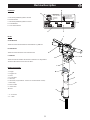
Serial Plate
A. Maximum permitted Hydraulic Oil Flow.
B. Breaker Model.
C. Maximum permitted Hydraulic Pressure.
D. Serial Number.
E. Year of Manufacture.
Decals
A. Model Decal
This Decal shows the Model Name of the Breaker. E.g ‘BHB 19’
B. Noise Decal
This Decal shows the Noise Level of the machine.
C. CE Decal
This Decal indicates whether the machine conforms to CE Regulations.
The Decal will not be found on USA machines.
Machine Components
1. Trigger
2. Trigger Lock
3. Head
4. Accumulator
5. Oil In (P*)
6. Oil Return (T**) (Restrictor - Please see ‘Technical Data’ section)
7. Main Body
8. Nose Section
9. ‘Steel’ Latch
10. Steel
* P = Pressure
** T = Tank
MODEL
FLOW
LPM
NO
MAX.
PRESS.
BAR
Belle Group
Sheen, Nr. Buxton,
Derbyshire,
SK17 0EU,
UK
www
+44 (0)1298 84606
+44 (0)1298 84722
www.BelleGroup.com
YEAR
A
E
C
D
B
Machine Description
GB
2
9
8
7
4
5
6
3
1
A
B
C
P
10

6
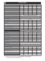
Technical Data
GB
Model BHB12 BHB19 BHB23 BHB19 USA BHB25X
Restrictor Open Open Open Open Open
Weight (Kg) 14 19 23.5 19 27.5
Hydraulic Flowrate (Ltrs/Min) 20 20 20 20 20
Working Pressure (Bar) 70 - 90 90 - 110 90 - 110 90 - 110 90 - 110
Max Pressure (Bar) 160 160 160 160 160
Max. Return Line Pressure (Bar) 10 10 10 10 10
EHTMA Category C C C C C
Hydraulic Connections
1
/2 BSP
1
/2 BSP
1
/2 BSP
1
/2 JIC
1
/2 BSP
Hydraulic Oil Type
- Below 30ºc ISO VG T32
- Above 30ºc ISO VG T46
Blow Frequency (Blows/Min) 2400 1600 1600 1600 1600
Accumulator Gas Pressure (Bar) 40 40 40 40 40
Steel Size (mm) 22 x 82 25 x 108 25 x 108 32 x 152 32 x 160
Recommended Power Pack Cub 20/90 Cub 20/90 Cub 20/90 Midi 20/140 Midi 20/140
Midi 20/140 Midi 20/140 Midi 20/140 Major 20/140 Major 20/140
Prelimenary Vibration - Cub (m/s
2
) 14.13 9.78 9.78 9.78 6.00
Prelimenary Vibration - Midi (m/s
2
) 16.08 11.97 11.97 11.97 6.00
Noise Level - Cub (dB(A)) 101.74 102.67 102.67 102.67 107.00
Noise Level - Midi (dB(A)) 104.30 104.03 104.03 104.03 107.00
Flat Faced, Quick Release, Non-Drip Couplings
Model BHB25 BHB27 * BHB30 USA *
Restrictor (mm) 3.8 3.4 Open 3.8 Open
Weight (Kg) 28 28 28 31.5 31.5
Hydraulic Flowrate (Ltrs/Min) 20 20 30 20 30
Working Pressure (Bar) 105 - 125 105 - 125 105 - 125 105 - 125 105 - 125
Max Pressure (Bar) 160 160 160 160 160
Max. Return Line Pressure (Bar) 20 20 20 20 20
EHTMA Category C C D C D
Hydraulic Connections
1
/2 BSP
1
/2 BSP
1
/2 BSP
1
/2 JIC
1
/2 JIC
Hydraulic Oil Type
- Below 30ºc ISO VG T32
- Above 30ºc ISO VG T46
Blow Frequency (Blows/Min) 1300 1300 2150 1150 1850
Accumulator Gas Pressure (Bar) 50 50 50 50 50
Steel Size (mm) 32 x 160 32 x 160 32 x 160 32 x 152 32 x 152
Recommended Power Pack Midi 20/140 Midi 20/140 Major 30/140 Midi 20/140 Major 30/140
Major 20/140 Major 20/140 Major 20/140
Prelimenary Vibration (m/s
2
) 11.1 11.8 18.61 10.75 16.06
Noise Level (dB(A)) 106.36 105.86 105.34 107.16 105.73
Flat Faced, Quick Release, Non-Drip Couplings
* NOTE:- Breakers are supplied with alternative return pipe restrictors. Please ensure correct restrictor is fi tted for 20 or 30 Litre supply.
(Restrictor size is marked on the restrictor body) NO MARKINGS = OPEN RESTRICTOR
More information can be found on the next page.

7
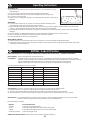
Matching The Breaker To The Power Pack
GB
Restrictor / Fitting Identifi cation
The tank Restrictors / Fittings can be identifi ed by using this simple procedure.
Check your Breaker and identify the P and T side of the body by looking for a
letter stamp on the large bung. This can be found on the side of the Breaker as
shown in the diagram. This stamp also corresponds to the Restrictor / Fitting on
the same side of the Breaker
For example: In the image the bung on the left hand side of the Breaker is clearly
stamped with the letter P, so the fi tting on the left hand side will be the Pressure
Line and the right hand side will be the Tank / Return Line.
P = Pressure side of the Breaker
T = Tank / Return side of the Breaker
Oil Flow Rate EHTMA Category Part Number Restrictor Size Notes
20 Ltrs/Min C 971/99061 3.4mm Delivered with the Breaker (Loose)
30 Ltrs/Min D 971/99006 No Restrictor (Open) Fitted onto the Breaker
Replacing The Restrictor
1. Disconnect the Breaker from the Power Pack.
2. Fix the Breaker in vertical position to a vice or in another way so that the Breaker is fi xed.
Do not place it on the Nose Section because the Breaker can tilt.
3. Remove the Tank Line Hose, leaving the Restrictor / Fitting in the Breaker body. Remember to have an oil pan ready to take the oil
spill from the Breaker. Drain the oil from the T-Hose into the oil pan.
4. Loosen the Restrictor on the Breaker. Remember to have an oil pan ready to take the oil spill from the Breaker.
5. Remove the Seal from the old Fitting / Restrictor. Fit the new Restrictor using the existing Seal, ensuring that the internal Allen Key
head in the Restrictor is fi tted into the Breaker body fi rst. Tighten to a Torque Setting of 90±2 Nm.
6. Refi t the Hose and tighten to a Torque Setting of 50±2 Nm.
7. Reconnect the Breaker to Power Pack and check it for leakage.
NOTE:- When the Breaker is modifi ed to another oil fl ow rate, do not connect a Power Pack with higher oil fl ow rate.
We recommend that the EHTMA Label on the Breaker is changed to Category C (Green) (Supplied loose with Breaker)), if Restrictor
(971/99061) is fi tted. Section A of the Serial Plate (See ‘Machine Description’ section) should also be amended.
Connecting the Breaker to a higher oil fl ow rate may cause damaged to the Power Pack or to the Breaker.
DO NOT attempt to change the Restrictor immediately after use as the Hydraulic Oil will be hot.
CAUTION
P
Large
Bung (P)
Fitting (P)
Restrictor /
Fitting (T)
BHB27 & BHB30 USA ONLY!!
At delivery, the Breaker is intended for an oil fl ow of 30 Ltrs/Min (E.H.T.M.A. Category D). If the Breaker is to be connected to a
Hydraulic Power Pack with an Oil Flow of 20 Ltrs/Min (E.H.T.M.A. Category C) the Restrictor / Fitting of the tank line (T) must be
replaced:- See Item 6 of ‘Machine Description’ section.
Restrictors / Fittings
You must only ever change the TANK Line Restrictor / Fitting as you may cause harm to your Breaker
and Power Pack if the PRESSURE Line Fitting is changed.
WARNING

8
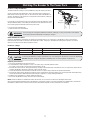
Safety Instructions
To reduce risk of serious injury or death to yourself or others, read these safety instructions before
operating the machine. Post these safety instructions at work locations, provide copies to employees, and
make sure that everyone reads the safety instructions before operating or servicing the machine.
Follow all safety instructions given in this manual. All the safety instructions conform to the applicable
laws and directives of the European Union. You should also respect any additional national/regional
directives. In countries outside the European Union, the valid local statutes and regulations shall apply.
Any additional regional laws and regulations must be observed.
WARNING
GB
Machine and Tool operating Hazards
Sudden or unexpected movement of the machine may occur during operating, which may cause injuries. Furthermore, losing your bal-
ance or slipping may cause injury. To reduce risks:
• Make sure that you always keep a stable position with your feet as far apart as the width of your shoulders, and keeping your
body weight balanced out.
• Stand fi rmly and always hold on to the machine with both hands.
• Do not start the machine when it is lying on the ground.
• Make sure that the handles are clean and free from grease and oil.
Unintentional start of the machine may cause injury!
• Keep your hands away from the start and stop device until you are ready to start work.
The working tool is exposed to heavy strains when the machine is used and after a certain amount of use the tool may break due to
fatigue. If the tool breaks, there may be sudden or strong movements. Such sudden or strong movements may cause serious injury.
• Make sure that you always keep a stable position with your feet as far apart as the width of your shoulders, and keeping your body
weight balanced.
• Keep your hands and feet away from the working tool.
• Do not ‘ride’ on the machine with one leg over the handle, since you could be seriously injured if the tool were to break suddenly.
• Check regularly for wear to the working tool, and check whether there are any signs of damage or visible cracks.
An incorrect dimension of the working tool’s shank can result in the working tool being lost or slipping out during operation. A working
tool that is lost or slips out can cause personal injury.
• Before inserting the work tool, make sure that the shank’s dimensions are correct for use in the machine.
• Working tools without a collar may not be used.
If the tool retainer on the machine is not in a locked position, the tool can be ejected with force, which can cause personal injury.
• Once the working tool has been mounted and locked, the locking function must be checked by pulling the working tool outwards
forcefully.
• Make sure that the tool is fully inserted and the tool retainer is in the locked position before the machine is started.
• Never point the working tool at yourself or anyone else.
Starting the machine while changing the working tool may cause personal injury.
• Before changing the tool, stop the machine, switch off the hydraulic oil supply and bleed the machine by activating the start and
stop device.
A hydraulic hose that comes loose can lash around and cause personal injury or death. To reduce risks:
• Check that the hydraulic hose and the connections are not damaged.
• Check that all hydraulic connections are properly attached.
• Never attempt to disconnect a hydraulic hose that is pressurized. First switch off the hydraulic oil fl ow by the power pack and then
bleed the machine by activating the start and stop device.
Accumulator Hazard
The machine has a pressure accumulator. The pressure accumulator may only be charged with nitrogen gas (N
2
).
• Only authorized personnel are qualifi ed to work with the accumulator.
• Do not perform any work on the machine, the connections or any hoses, when the hydraulic system is pressurized.
NOTE!:- If the maximum working pressure for the machine is exceeded, the accumulator can be overcharged, which can result in
material damage.
• Always run the machine with the correct working pressure. See “Technical Data” section.

9
Safety Instructions
GB
Hydraulic Oil and Lubrication Hazards
Thin jets of hydraulic oil under high pressure can penetrate the skin and cause permanent damage.
• Never use your hands when searching for oil leaks.
• Keep your face away from any possible leaks.
• Immediately seek medical attention if hydraulic oil has penetrated the skin.
Spilled hydraulic oil can cause accidents by causing slippery conditions and will also harm the environment.
• Handle the hydraulic oil with care.
• Take care of all spilled oil and handle it according to your local safety and environmental regulations.
Hot hydraulic oil can cause burns.
• Never dismount the machine when the hydraulic oil is hot.
Hydraulic oil can cause eczema when it comes in contact with the skin.
• Avoid getting hydraulic oil on your hands.
• Always use protective gloves when working with hydraulic oil.
Grease can cause eczema when it comes in contact with the skin.
• Avoid getting grease on your hands.
Explosion and Fire Hazard
Breaking, drilling and working with certain materials can cause sparks, which may ignite explosive gases and cause explosions.
Explosions may cause serious injury or death. To reduce such risk of explosion:
• Never operate the machine in any explosive environment.
• Do not use the machine near fl ammable materials, fumes or dust.
• Make sure that there are no undetected sources of gas.
Electrical/Concealed Object Hazards
The machine is not electrically insulated. If the machine comes into contact with electricity, serious injuries or death may result.
• To reduce the risk of such injury or death, never operate the machine near any electric wire or other source of electricity.
• Make sure that there are no concealed wires or other sources of electricity.
During breaking, concealed wires and pipes constitute a danger that can result in serious injury.
• Before you start breaking, check the composition of the material you are to work on.
• Watch out for concealed cables and pipes e.g. electricity, telephone, water, gas and sewage lines etc.
• If the tool seems to have hit a concealed object, switch off the machine immediately.
• Make sure that there is no danger before continuing.
Projectile Hazard
During breaking, drilling or hammering, splinters or other particles from the worked material may become projectiles and cause
personal injury by striking the operator or other persons.
• Use approved personal protective equipment, including impact resistant safety glasses with side protection, to reduce the risk of
being injured by a projectile.
Noise Hazard
High sound levels may cause permanent hearing loss.
• Use hearing protection in accordance with occupational health and safety regulations.

10
Silica/Dust Hazard
Exposure to crystalline silica (sometimes called ‘silica dust’) as a result of breaking, drilling, hammering, or other activities involving
rock, concrete, asphalt or other materials may cause silicosis (a serious lung disease), silicosis-related illnesses, cancer, or death.
Silica is a major component of rock, sand and mineral ores. To reduce silica exposure:
• Use proper engineering controls to reduce the amount of silica in the air and the build-up of dust on equipment and surfaces.
Examples of such controls include: Exhaust ventilation and dust collection systems, water sprays, and wet drilling. Make sure that
controls are properly installed and maintained.
• Wear, maintain, and correctly use approved particulate respirators when engineering controls alone are not adequate to reduce
exposure below permissible levels.
• Participate in air monitoring, medical exams, and training programs offered by your employer and when required by law.
• Wear washable or disposable protective clothes at the worksite; shower and change into clean clothes before leaving the worksite
to reduce exposure of silica to yourself, other persons, cars, homes, and other areas.
• Do not eat, drink, or use tobacco products in areas where there is dust containing crystalline silica.
• Wash your hands and face before eating, drinking, or using tobacco products outside of the exposure area.
• Work with your employer to reduce silica exposure at your worksite.
Some dust, fumes or other airborne material created during use of the machine may contain chemicals known to the State of California
to cause cancer and birth defects or other reproductive harm. Some examples of such chemicals are:
• Crystalline silica and cement and other masonry products.
• Arsenic and chromium from chemically-treated rubber.
• Lead from lead based paints.
To reduce your exposure to these chemicals, work in a well ventilated area, and work with approved safety equipment, such as dust
masks that are specially designed to fi lter out microscopic particles.
Machine Modifi cation Hazard
Any machine modifi cation not approved by Belle Group may result in serious injuries to yourself or others.
• The machine must not be modifi ed without Belle Groups permission.
• Use only original parts and accessories approved by Belle Group.
Vibration Hazard
Normal and proper use of the machine exposes the operator to vibration. Regular and frequent exposure to vibration may cause,
contribute to, or aggravate injury or disorders to the operator’s fi ngers, hands, wrists, arms, shoulders and/or other body parts,
including debilitating and/or permanent injuries or disorders that may develop gradually over periods of weeks, months, or years. Such
injury or disorder may include damage to the blood circulatory system, damage to the nervous system, damage to joints, and possibly
damage to other body structures.
If numbness, tingling, pain, clumsiness, weakened grip, whitening of the skin, or other symptoms occur at any time, when operating the
machine or when not operating the machine, do not resume operating the machine and seek medical attention. Continued use of the
machine after the occurrence of any such symptom may increase the risk of symptoms becoming more severe and/or
permanent.
The following may help to reduce exposure to vibration for the operator:
• Let the tool do the job. Use a minimum hand grip consistent with proper control and safe operation.
• When the impact mechanism is activated, the only body contact with the machine you should have is your hands on the handles.
Avoid any other contact, e.g. supporting any part of the body against the machine or leaning onto the machine trying to increase the
feed force. It is also important not to keep the trigger engaged while extracting the tool from the broken work surface.
• Make sure that the inserted tool is wellmaintained (including sharpness, if a cutting tool), not worn out, and of the proper size.
Working tools that are not well-maintained, or that are worn out, or that are not of the proper size result in longer time to complete a
task (and a longer period of exposure to vibration) and may result in or contribute to higher levels of vibration exposure.
• Immediately stop working if the machine suddenly starts to vibrate strongly. Before resuming the work, fi nd and remove the cause
of the increased vibrations.
• Comply with the recommended hydraulic pressure when operating the machine. Either higher or lower hydraulic pressure has the
potential of resulting in higher levels of vibration.
• Do not grab, hold or touch the inserted tool when using the machine.
• Participate in health surveillance or monitoring, medical exams, and training programs offered by your employer and when required
by law.
NOTE!:- See the Noise and Vibration Levels for the machine, which can be found in the Technical Data section
Safety Instructions
GB

11
General Safety
GB
• Machines and accessories must only be used for their intended purpose.
• Only qualifi ed and trained persons may operate or maintain the machine.
• Learn how the machine is switched off in the event of an emergency.
• Release the start and stop device immediately in all cases of power supply interruption.
• Always inspect the equipment prior to use. Do not use the equipment if you suspect that it is damaged.
• Always use your common sense and good judgment.
• Pay attention and look at what you are doing.
• Do not use the machine when you are tired or under the infl uence of drugs, alcohol or anything else that may affect your vision,
reactions or judgment.
• Participate in safety and training courses.
• Never strike or abuse any equipment.
• Keep the machine and tools in a safe place, out of the reach of children and locked up.
• Make sure that all the attached and related equipment is properly maintained.
• Decals bearing important information regarding personal safety and care of the machine are supplied with every machine.
• Make sure that the decals are always legible.
• New decals can be ordered from the Spare Parts list.
• Make sure that no unauthorized personnel trespass into the working zone.
• Keep the workplace clean and free from foreign objects.
• Never point a hydraulic hose at yourself or anyone else.
PPE (Personal Protective Equipment)
Always use approved protective equipment. Operators and all other persons in the working area must wear protective equipment,
including at a minimum:
• Protective helmet.
• Safety Goggles,
• Gloves,
• Ear Defenders,
• Dust Mask
• Steel Toe capped footwear.
Wear clothing suitable for the work you are doing. Tie back long hair and remove any jewellery which may catch in the equipment’s
moving parts.
Recommended Hydraulic Oil
GB
In order to protect the environment, Belle Group recommends the use of biologically degradable hydraulic oil.
• Viscosity (preferred) 20-40 cSt.
• Viscosity (permitted) 15-100 cSt.
• Viscosity index Min. 100.
Standard mineral or synthetic oil can be used. When the breaker is used continuously, the oil temperature will stabilise at a level which
is called the working temperature. This will, depending on the type of work and the cooling capacity of the hydraulic system, be be-
tween 20-40°C (68-104°F) above the ambient temperature.
At working temperature, the oil viscosity must lie within the preferred limits. The viscosity index indicates the connection between vis-
cosity and temperature. This is the reason why a high viscosity is preferred, because then the oil can be used within a wider tempera-
ture range. The breaker shall not be used, if oil viscosity fails to remain within the permitted area, or if the working temperature of the oil
does not fall between ÷20°C (÷4°F) and 70°C (158°F).
Storage
GB
• Disconnect the breaker’s hoses from the power source. See “Start and Stop Procedure” section
• Make sure that the breaker is properly cleaned before storage.
• In case of long-term storage, the striking piston must be protected against corrosion. This is done by pressing it (through the chisel
bushing) to its upper position by means of a tool placed up-side-down. As the quick-release couplings are blocked when
disassembled, the striking piston must be pressed upwards with the hoses mounted but the power pack unactivated.
• Always store the machine in a dry place.

12
Pre-Start Checks
The following checks should be made each time you start to use the breaker. All these checks concern the serviceability of the breaker.
Some concern your safety:
• Clean all Decals. Replace any that are missing or cannot be read. These can be ordered from the Spare Parts list.
• Inspect the hoses generally for signs of damage.
• Inspect the working tool for wear and damage.
• Do not use an excessively worn or damaged tool.
• Connect the tool.
• Ensure that the hydraulic couplings are clean and fully serviceable.
• Do not invert the breaker without fi rst isolating it from the power source. The working tool might be fi red out while connecting it, if
the breaker is connected to the power source.
• Ensure that any power source you plan to use is compatible with the breaker model used (see the “Technical data” section). Belle
Group recommends using an LFD oil fl ow divider, if the fl ow from the power source can exceed the maximum allowed oil fl ow.
Pre-Start Checks
GB
Start and Stop Procedure
GB
Starting
1) Check that the ‘Steel’ is in good condition and pressed fully home in the nose of the breaker.
2) Check that the latch is locked, so that the ‘Steel’ does not fall out.
3) Remove the protective caps from the quick-release couplings.
4) Clean the quick-release couplings if needed and connect the tail-hoses to the extension hoses of the power unit.
5) Place the breaker at a right angle on the material to be broken and activate the trigger lever.
Stopping
1) Release the trigger. Press the breaker against the surface, until the breaker has stopped completely.
2) Stop the power source.
3) Disconnect the hoses and fi t the protective caps to the quick-release couplings.
Environment
GB
A used machine must be treated and disposed of in such a way that the greatest possible portion of the
material can be recycled and any negative infl uence on the environment is kept as low as possible.
NOTE:-
Before a used machine is scrapped, it must be emptied and cleaned from all hydraulic oil. Remaining
hydraulic oil must be deposited.

13
Operating Instructions
GB
To reduce the risk of serious injury or death to yourself or others, before operating the machine, read the Safety instructions section
found on the previous pages of this booklet.
Design and Function
The Belle Group BHB Range of handheld Hydraulic Breakers are sturdy and reliable breakers designed for working together with Belle
Group Hydraulic Power Packs.
The handheld Breakers are available in many different sizes with varying impact energies and commonly used tool sizes. The handheld
Breakers are designed for various jobs from light brickwork and asphalt jobs to heavy duty jobs in reinforced concrete.
All Belle Group BHB Range handheld breakers are delivered with ½” tail-hoses with ½” Flat-Face quick-release couplings for easy
connection to the Belle Group Hydraulic Power Packs.
Choosing the correct hydraulic breaker for a task
It is important to choose the correct size of hydraulic breaker for the work to be performed.
A hydraulic breaker that is too small means that the work will take longer.
A breaker that is too big means that there must be frequent repositioning, which is unnecessarily tiring for the operator.
A simple rule for choosing the correct size of hydraulic breaker is that a normal sized piece of broken material should be removed from
the workpiece within 10–20 seconds of operation.
• If it takes less than 10 seconds a smaller hydraulic breaker should be selected.
• If it takes more than 20 seconds a larger hydraulic breaker should be selected.
Installation
Hoses
For connection of the breaker, the hydraulic hose must be approved for a working pressure of at least 200 bar (2900 psi) and have a
½” inner diameter. To resist exterior wear and tear, we recommend using a 2-layer hydraulic hose. The breaker connection marked P
(pump) is oil inlet, and the connection marked T (tank) is oil outlet.
Quick-release couplings
The original Belle Group hydraulic hoses are fi tted with Flat-Face quick-release couplings that are strong and easy to clean. The quick-
release couplings are fi tted so that the male connection supplies oil and the female connection receives oil.
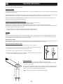
Fitting and Removing the Breaker ‘Steel’
Whenever fi tting/removing the ‘Steel’, the following instructions must be observed:
1) To prevent an accidental start, switch off the oil supply. Bleed the machine by pressing the
start/stop device. Disconnect the machine from the power source.
2) Remove the ‘Steel’ by swinging the latch (C) fully down (Image A).
3) Fit a ‘Steel’ by ensuring that the latch (C) is fully down. Then insert the ‘Steel’ in the breaker
as shown and swing the latch (C) fully up (Image B).
Checking for wear
Using a working tool with a worn out shank leads to increased machine
vibrations. To avoid increased vibrations, check the shank for wear before the working
tool is fi tted in the machine.
Use the checking gauge that corresponds to the working tool’s shank dimension. If the
gauge’s hole (2) can be pushed down on the working tool’s shank, this means that the
shank is worn out and the working tool should be replaced.
* Note:- The Checking Gauge is not supplied with the machine.
A
B
C
C
2

14
Operating Instructions
GB
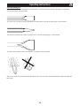
Choosing working tool
A correct working tool is a prerequisite for good operation. To avoid unnecessary machine damage, it is important to
choose working tools of a high quality.
The narrow chisel should be used for demolition and cutting work in concrete and other types of hard material.
The moil point should only be used for creating holes in concrete and other types of hard material.
The wide chisel should be used in soft materials e.g. asphalt and frozen ground.
Always use a sharp tool to be able to work effectively. A worn out tool causes increased vibrations and the operation will
take longer.

15
STARTING A CUT
1) Stand steady and make sure that your feet and hands are at a safe distance from the
working Breaker.
2) Press the machine against the surface of the workpiece before starting.
3) Adjust the breaking distance (A) so that the working Breaker does not get stuck.
4) Do not try to cut too big a bite.
5) Trying to loosen a working Breaker that is stuck will expose the operator to unnecessary
vibrations.
OPERATION
1) Let the machine do the work; do not press too hard. The vibration-absorbing handle
must absolutely not be pressed all the way down to the base.
2) Hydraulic breakers with vibration-absorbing handles: The feed force should be adapted so that the handles are pressed down
“half way”. The best vibration damping and breaking effect is achieved at this position.
3) Avoid working in extremely hard materials e.g. granite and reinforcing iron (reinforcement bar), which would cause substantial
vibrations.
4) Any form of idling, operating without working tool or operating without adapted feed force must be avoided.
5) When no feed force is applied, the start and stop device must not be activated.
6) Check regularly that the machine is well lubricated.
WHEN TAKING A BREAK
1) During all breaks you must put the machine away so that there is no risk that it will be unintentionally started.
2) In the event of a longer break or when leaving the workplace: Switch off the hydraulic oil supply and then bleed the machine by
activating the start and stop device.
A
Operating Instructions
GB
EHTMA - Code Of Practice
GB
EUROPEAN HYDRAULIC TOOL MANUFACTURERS ASSOCIATION CODE OF PRACTICE – HYDRAULIC BREAKERS
Before Starting. Refer to manufacturer’s operating instructions.
Compatibility. Hydraulic Breakers are designed to operate at a specifi c Flow and Pressure. Equipment produced by EHTMA
members carries a triangular colour coded range identifi cation label. Check that both the Tool and Power Unit have
the same identifi cation label before operation. It is imperative that Power Units and Tools having
different colour codings are not interconnected as this practice is both ineffi cient and dangerous.
For reference the EHTMA colour code is as follows:-
If in doubt consult the equipment manufacturer.
Characteristics. Operators not familiar with the use of hydraulic tools should note the following points:-
1) Hydraulic breakers are usually more powerful than the equivalent weight pneumatic tools.
2) The body of the hydraulic breaker and the supply hoses will become quite warm during normal operation.
3) As the breaker has no exhaust it is generally much quieter in operation. This should not be taken as a lack of power.
Steel Selection It is essential that the correct type and size of steel is chosen if optimum performance is to be achieved, with
particular reference being made to the shank length and across fl at dimensions.
Recommendations as follows:-
Material. Recommended Steel
Concrete. Pointed or narrow bladed chisels.
Tarmac. Sharp edged wide bladed tools with straight cutting edges.
Asphalt. Sharp edged tools with thin section and curved cutting edges.
General Trenchwork. Spades and Digger steels.
ALWAYS USE SHARP STEELS - Blunt steels increase vibration and reduce effi ciency.
Classifi cation Colour Code. Flow l/min Max pressure Bar.
A Yellow 5.5 – 6.5 180
B Blue 13.5 – 16.5 172
C Green 18.0 – 22.0 138
D Brown 27.0 – 33.0 138
E Red 36.0 – 44.0 138
F Black 45.0 – 55.0 138
G Orange 54.0 – 66.0 138
Z Grey 9.0 – 11.0 180

16
Service and Maintenance
GB
Regular maintenance is a prerequisite for keeping the machine safe and effective. Carefully follow the operating instructions.
Before undertaking any maintenance or changing the working tool on hydraulic machines, always switch off the oil supply and bleed the
machine by depressing the start and stop device Then disconnect the hydraulic hose from the machine.
• Use only authorized parts. Any damage or malfunction caused by unauthorized parts will not be covered by Warranty or Product
Liability.
• Change damaged parts immediately.
• Replace worn components in good time.
• Always clean the hose couplings before mounting or dismounting.
• Always plug hoses and nipples with clean and tight plugs when dismounting.
• When cleaning mechanical parts with solvent, make sure to comply with occupational health and safety regulations, and make sure
that there is satisfactory ventilation.
• Inspection and service on the accumulator must only be done by a certifi ed person.
• For major service to the machine, contact the Belle Group or your nearest authorised dealer.
NOTE!:- Maintenance must only be done by suitably qualifi ed and competent persons. Before doing any maintenance, make sure that
the machine is safe and correctly sited on the ground.
Routine Maintenance Every Week Every 3 Every 600
Months Hrs / Yearly
Clean and inspect the machine. 9
Grease the Handle Guides with Silicone (E-Type Handles only) 9
Check Hoses and Fittings for cracks or leaks. Replace if necessary. 9
Inspect the ‘Steel’ for wear and damage. Do not use an worn or damaged ‘Steel’. 9
Check for general damage to the machine. 9
If the machine is equipped with Vibration-Absorbing handles, their function should 9
be checked.
Check that the handles are moving freely (up - down) and do not jam. 9
Check that the springs are not damaged. 9
Check tightness of nuts, bolts, screws and hose fi ttings. 9
Check the Chisel bushing in the nose for wear and damage. 9
Check moving parts, seals and bolts for wear and cracks. Replace if necessary. 9
Check the function of the machine. 9
For the machine to maintain the specifi ed vibration values, this should always be checked:
Too big a clearance between the working tool’s shank and the chisel bushing will generate increased vibrations. To avoid exposure
to excessive vibrations, check the chisel bushing for wear every day. Use the gauge that corresponds to the working tool’s shank
dimension. If the gauge´s part (A) can be pushed fully into the chisel bushing (B), the bushing is worn out and must be replaced! See
also “Checking for wear” section for checking the working tool’s shank.
A
B

17
Troubleshooting Guide
GB
Warranty
GB
Your new Belle Group BHB Hydraulic Breaker is warranted to the original purchaser for a period of one-year (12 months) from the
original date of purchase. The Belle Group warranty is against defects in design, materials and workmanship.
The following are not covered under the Belle Group warranty:
1. Damage caused by abuse, misuse, dropping or other similar damage caused by or as a result of failure to follow assembly,
operation or user maintenance instructions.
2. Alterations, additions or repairs carried out by persons other than Belle Group or their recognised agents.
3. Transportation or shipment costs to and from Belle Group or their recognised agents, for repair or assessment against a warranty
claim, on any machine.
4. Materials and/or labour costs to renew, repair or replace components due to fair wear and tear.
Belle Group and/or their recognised agents, directors, employees or insurers will not be held liable for consequential or other damages,
losses or expenses in connection with or by reason of or the inability to use the machine for any purpose.
Warranty Claims
All warranty claims should fi rstly be directed to Belle Group, either by telephone, by Fax, by Email, or in writing.
For warranty claims:
Belle Group Warranty Department,
Unit 5, Bode Business Park,
Ball Haye Green,
Leek,
Staffordshire,
ST13 6BW
England.
Problem Cause Remedy
Breaker does not work. No or incorrect fl ow/pressure. Check fl ow/pressure by means of test equipment.
Pressure is not built P and T hoses interchanged. Check connection. Standard connection has oil fl owing from
up when trigger is male quick-release coupling (i.e. the tail-hose of the breaker P
activated. connection is fi tted with female coupling).
Insuffi cient activation of trigger valve. Adjust trigger lever (if adjustable) or replace defective parts.
Seals defect in spool channel of Dismount, check and replace seals.
valve housing.
Breaker does not Back pressure too high. Make direct tank connection. Max. back pressure 10-15 bar
work. Pressure is built (150-200 psi) measured at breaker.
up when trigger is Quick-release coupling in return line Locate and replace defective coupling.
activated defective.
Striking piston sticks, possibly due to Push the breaker hard against the Breaker ‘Steel’.
thickening of cylinder. Chamfer/polish the edge slightly at the cylinder dashpot (where
the cylinder bore changes size).
Check oil viscosity. Thin oil increases the risk of thickening.
Spool / reversing spool or auxiliary Dismount and check that all parts move. Polish slightly if
spool sticking easily. necessary.
Seals defective. Dismount, check and replace.
Breaker runs weakly or Insuffi cient fl ow. Check fl ow/pressure.
irregularly Seals defective. Replace seals.
Wear, internal leakage. Dismantle, check and replace defective or worn parts.
Check impurity of oil and oil viscosity at working temperature.
Thin oil = increased internal leakage.
Insuffi cient accumulator charge. Recharge accumulator.
Diaphragm defective. Replace diaphragm.
Hoses pulsate Accumulator defective. Replace accumulator diaphragm and charge with nitrogen.
Oil leaking from breaker. Seals defective. Replace seals.
‘Steel’ falls out. Worn latch. Replace latch and roll pins.
Worn chisel bushing or ‘Steel’. Replace bushing or ‘Steel’.

18
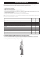
1-01
1-01
Top Cover Assembly, Boitier de commande complet ,
Montaje Tapa Superior, Montagem da Cobertura Superior
1 971/00101 ........... Head ............................................................................................................................................................................................................................1
2 01997 .................. Handle ...............................Guidon ...............................Manillar .............................. Pega .........................................................................................1
3 01998 .................. Handle ...............................Guidon ...............................Manillar .............................. Pega .........................................................................................1
4 02203-00 ............. Trigger ...............................Déclenchement ..................Disparador ......................... Gatilho ......................................................................................1
5 3/0074 .................Spirol Pin ..........................Goupille Spirol ....................Pasador ´Spirol´ ................ Pino em Espiral ................................10 x 45............................2
6 2/0062 ................. Spring ................................Ressort ...............................Resorte .............................. Mola .......................................................................................... 1
7 01873 .................. Spring ................................Ressort ...............................Resorte .............................. Mola .......................................................................................... 1
8 01931 .................. Washer ..............................Rondelle .............................Arandela ............................ Anilha ........................................................................................1
9 10-404-2000 ........ Washer ..............................Rondelle .............................Arandela ............................ Anilha ........................................................................................1
10 01999 ..................Hand Grip ..........................Poignée ..............................Asas .................................. Punho .......................................................................................2
11 9/12034 ...............Screw .................................Vis ......................................Tornillo ............................... Parafuso ...........................................M12 x 70.........................2
12 10-406-1200 ........Washer ..............................Rondelle .............................Arandela ............................ Anilha ................................................M12 ................................2
13 971/99101 ...........Lever ..................................Levier .................................Palanca ............................. Alavanca ................................................................................... 1
14 3/0075 ................. Spirol Pin ..........................Goupille Spirol ....................Pasador ´Spirol´ ................ Pino em Espiral ................................5 x 26 .............................1
15 971/10800 ...........Trigger Kit ....................................................................................................................................................................................................................1
BHB 19, BHB 19 USA, BHB 23, BHB 25, BHB 27 & BHB 30 USA
10
11
1
12
4
10
9
8
13
7
2
14
6
5
5
3

19
13
20
18
11
3
5
19
17
16
11
10
7
9
8
2
1
12
4
14
15
7
21
Top Cover Assembly, Boitier de commande complet ,
Montaje Tapa Superior, Montagem da Cobertura Superior
1-02
1-02
1 01949-00 ............. UD Head Machined ......................................................................................................................................................................................................1
2 01997 .................. Handle ...............................Guidon ...............................Manillar .............................. Pega ..........................................................................................1
3 01998 .................. Handle ...............................Guidon ...............................Manillar .............................. Pega ..........................................................................................1
4 02203-00 ............. Trigger ...............................Déclenchement ..................Disparador ......................... Gatilho .......................................................................................1
5 3/0074 .................Spirol Pin ..........................Goupille Spirol ....................Pasador ´Spirol´ ................ Pino em Espiral ................................10 x 45.............................2
6 3/0075 .................Spirol Pin ..........................Goupille Spirol ....................Pasador ´Spirol´ ................ Pino em Espiral ................................5 x 26...............................1
7 971/99101 ........... Lever ..................................Levier .................................Palanca ............................. Alavanca ....................................................................................1
8 01873 .................. Spring ................................Ressort ...............................Resorte .............................. Mola ........................................................................................... 1
9 01931 .................. Washer ..............................Rondelle .............................Arandela ............................ Anilha .........................................................................................1
10 10-404-2000 ........Washer ..............................Rondelle .............................Arandela ............................ Anilha .........................................................................................1
11 01999 ..................Hand Grip ..........................Poignée ..............................Asas .................................. Punho ........................................................................................2
12 10-406-1200 ........Washer ..............................Rondelle .............................Arandela ............................ Anilha ................................................M12 .................................2
13 971/99102 ...........Cap ....................................Capuchon ...........................Casquete ........................... Tampa .......................................................................................1
14 10-330-1285 ........Screw .................................Vis ...................................... Tornillo ............................... Parafuso ...........................................M12 x 85..........................2
15 02307 ..................Ring ...................................Bague .................................Anillo .................................. Anel ...........................................................................................2
16 01957 ..................Bearing ..............................Roulement ..........................Cojinete ............................. Rolamento .................................................................................2
17 01994 ..................Cap ....................................Capuchon ...........................Casquete ........................... Tampa .......................................................................................2
18 M 486910S ..........Spring ................................Ressort ...............................Resorte .............................. Mola ...........................................................................................2
19 02306 ..................Tube ................................... Tube ................................... Tubo .................................. Tubo ..........................................................................................2
20 02012 ..................Buffer ................................Butoir ..................................Parachoques ..................... Amortecedor ..............................................................................2
21 2/0062 .................Spring ................................Ressort ...............................Resorte .............................. Mola ...........................................................................................1
22 971/10800 ...........Trigger Kit .....................................................................................................................................................................................................................1
BHB 25X

20
2-01
68
06
03
65
71
66
67
69
70
62
64
63
61
60
25
12
08
07
05
24
04
22
23
21
18
17
14
15
13
28
16
17
11
10
19
45
47
46
42
26
02
01
09
27
56
52
53
58
55
54
20
19
57
59
34
35
39
40
41
37
38
36
50
51
33
49
48
30
31
43
44
32
29
78
74
77
75
76
72
73
BHB 12
La pagina si sta caricando...
La pagina si sta caricando...
La pagina si sta caricando...
La pagina si sta caricando...
La pagina si sta caricando...
La pagina si sta caricando...
La pagina si sta caricando...
La pagina si sta caricando...
La pagina si sta caricando...
La pagina si sta caricando...
-
 1
1
-
 2
2
-
 3
3
-
 4
4
-
 5
5
-
 6
6
-
 7
7
-
 8
8
-
 9
9
-
 10
10
-
 11
11
-
 12
12
-
 13
13
-
 14
14
-
 15
15
-
 16
16
-
 17
17
-
 18
18
-
 19
19
-
 20
20
-
 21
21
-
 22
22
-
 23
23
-
 24
24
-
 25
25
-
 26
26
-
 27
27
-
 28
28
-
 29
29
-
 30
30


Belle Group BHB19 Manuale utente
- Tipo
- Manuale utente
- Questo manuale è adatto anche per
in altre lingue
- English: Belle Group BHB19 User manual
Documenti correlati
Altri documenti
-
Lescha BELLE PCX 500 Istruzioni per l'uso
-
Lescha BELLE RPC 45/60 Istruzioni per l'uso
-
-
-
Stanley AV15 Manuale utente
-
Stanley AV30 Manuale utente
-
 Erard CUB 1600 Manuale del proprietario
-
Graco 310761ZAU, Tubo riscaldato Power-Lock Manuale del proprietario
-
 Toku TPB501SVS Manuale del proprietario
-
Chicago Pneumatic CP0006, CP0006 SVR, CP0066 Istruzioni per l'uso

