Moog Videolarm IGDW75C1N Istruzioni per l'uso
- Categoria
- Accessori per telecamere di sicurezza
- Tipo
- Istruzioni per l'uso
Questo manuale è adatto anche per
La pagina si sta caricando...

IMPORTANT SAFEGUARDS SAFETY PRECAUTIONS
UNPACKING
SERVICE
1 Read these instructions.
2 Keep these instructions.
3 Heed all warnings
4 Follow all instructions.
5 Do not use this apparatus near water.
6 Clean only with damp cloth.
7 Do not block any of the ventilation openings. Install in accordance with the
manufacturers instructions.
8 Cable Runs- All cable runs must be within permissible distance.
9 Mounting - This unit must be properly and securely mounted to a supporting
structure capable of sustaining the weight of the unit.
Accordingly:
a. The installation should be made by a qualified installer.
b. The installation should be in compliance with local codes.
c. Care should be exercised to select suitable hardware to install the unit, taking into
account both the composition of the mounting surface and the weight of the
unit.
10 Do not install near any heat sources such as radiators, heat registers, stoves, or other
apparatus ( including amplifiers) that produce heat.
11 Do not defeat the safety purpose of the polarized or grounding-type plug. A
polarized plug has two blades with one wider than the other. A grounding type
plug has two blades and a third grounding prong. The wide blade or the third
prong are provided for your safety. When the provided plug does not fit into your
outlet, consult an electrician for replacement of the obsolete outlet.
12 Protect the power cord from being walked on or pinched particularly at plugs,
convenience receptacles, and the point where they exit from the apparatus.
13 Only use attachment/ accessories specified by the manufacturer.
14 Use only with a cart, stand, tripod, bracket, or table specified by the manufacturer,
or sold with the apparatus. When a cart is used, use caution when moving the cart/
apparatus combination to avoid injury from tip-over.
15 Unplug this apparatus during lighting storms or when unused for long periods of time.
16 Refer all servicing to qualified service personnel. Servicing is required when the
apparatus has been damaged in any way, such as power-supply cord or plug is
damaged, liquid has been spilled of objects have fallen into the apparatus, the
apparatus has been exposed to rain or moisture, does not operate normally, or
has been dropped.
Be sure to periodically examine the unit and the supporting structure to make sure that the
integrity of the installation is intact. Failure to comply with the foregoing could result in the
unit separating from the support structure and falling, with resultant damages or injury to
anyone or anything struck by the falling unit.
Unpack carefully. Electronic components can be
damaged if improperly handled or dropped. If an item
appears to have been damaged in shipment, replace
it properly in its carton and notify the shipper.
Be sure to save:
1 The shipping carton and packaging material.
They are the safest material in which to make
future shipments of the equipment.
2 These Installation and Operating Instructions.
If technical support or service is needed, contact us
at the following number:
The lightning flash with an arrowhead
symbol, within an equilateral triangle, is
intended to alert the user to the presence
of non-insulated “dangerous voltage”
within the product’s enclosure that may be
of sufficient magnitude to constitute a risk
to persons.
Este símbolo se piensa para alertar al usuario a la
presencia del “voltaje peligroso no-aisIado” dentro del
recinto de los productos que puede ser un riesgo de
choque eléctrico.
Ce symbole est prévu pour alerter I’utilisateur à la
presence “de la tension dangereuse” non-isolée dans la
clôture de produits qui peut être un risque de choc
électrique.
Dieses Symbol soll den Benutzer zum Vorhandensein der
nicht-lsolier “Gefährdungsspannung” innerhalb der
Produkteinschließung alarmieren die eine Gefahr des
elektrischen Schlages sein kann.
Este símbolo é pretendido alertar o usuário à presença
“di tensão perigosa non-isolada” dentro do cerco dos
produtos que pode ser um risco de choque elétrico.
Questo simbolo è inteso per avvertire I’utente alla
presenza “di tensione pericolosa” non-isolata all’interno
della recinzione dei prodotti che può essere un rischio di
scossa elettrica
.
The exclamation point within an equilateral
triangle is intended to alert the user to
presence of important operating and
maintenance (servicing) instructions in the
literature accompanying the appliance.
Este símbolo del punto del exclamation se piensa para
alertar al usuario a la presencia de instrucciones
importantes en la literatura que acompaña la
aplicación.
Ce symbole de point d’exclamation est prévu pour
alerter l’utilisateur à la presence des instructions
importantes dans la littérature accompagnant
l’appareil.
Dieses Ausruf Punktsymbol soll den Benutzer zum
Vorhandensein de wichtigen Anweisungen in der
Literatur alarmieren, die das Gerät begleitet.
Este símbolo do ponto do exclamation é pretendido
alertar o usuário à presença de instruções importantes
na literatura que acompanha o dispositivo.
Questo simbolo del punto del exclamaton è inteso per
avvertire l’utente alla presenza delle istruzioni importanti
nella letteratura che accompagna l'apparecchio.
TECHNICAL SUPPORT
AVAILABLE 24 HOURS
1- 800 - 554 -1124
RISK OF ELECTRIC SHOCK
DO NOT OPEN
CAUTION
CAUTION: TO REDUCE THE RISK OF
ELECTRIC SHOCK, DO NOT REMOVE
COVER ( OR BACK). NO USER- SERVICE-
ABLE PARTS INSIDE. REFER SEVICING TO
QUALIFIED SERVICE PERSONNEL.
La pagina si sta caricando...
La pagina si sta caricando...
La pagina si sta caricando...
La pagina si sta caricando...
La pagina si sta caricando...

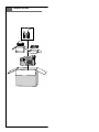
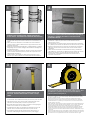
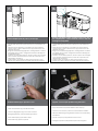
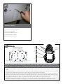
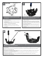
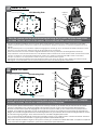
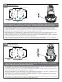
Installation is complete when nut is tight / secure and all slack has been removed from steel band.
• La instalación es completa cuando es apretado la tuerca / garantizar la seguridad de todos y la atonía se ha eliminado de la banda
de acero.
• L'installation est terminée lorsque l'écrou est serré, sécurité et tous les mou a été retiré de la bande d'acier.
• De installatie is volledig wanneer moer is strak / beveiligde en alle speling verwijderd is van staal-band.
• A instalação está completa quando porca é apertado / seguro e todos folga foi removido da banda de aço.
• L'installazione è completa quando il dado è stretto / e tutte le sicuro slack è stata rimossa dalla banda di acciaio.
8
Repeat for multiple band applications.
• Repetición para los usos de venda múltiples.
• Répétition pour des applications de bande multiples.
• Wiederholung für mehrfache Bandanwendungen.
• Repetição para aplicações de faixa múltiplas.
• Ripetizione per le applicazioni di fascia multiple.
From
A-Z
9
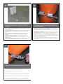
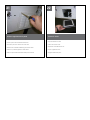
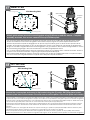
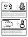
Locate and drill (4) holes 2” deep
• Localice y perfore (4) los agujeros 2” profundamente
• Trouvez et forez (4) les trous 2 » profondément
• Lokalisieren Sie und bohren Sie (4) Löcher 2“ tief
• Encontre e perfure (4) furos 2” profundamente
• Individui e perfori (4) fora 2„ in profondità
(4) holes
10

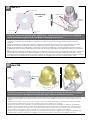
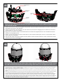
Place the mounting plate against the wall
• Coloque la pletina contra la pared
• Placez le plat de support contre le mur
• Setzen Sie die Montageplatte gegen die Wand
• Coloc a placa de montagem de encontro à parede
• Disponga il giunto di supporto contro la parete
Attach with (4) anchor bolts, (4) lock washers, and (4)
flat washers
• Fijación con (4) los pernos de ancla, (4) arandelas de cerradura, y (4) arandelas
planas
• Attache avec (4) des boulons d'anchrage, (4) rondelles de freinage, et (4) rondelles
plates
• Befestigung mit (4) Ankerbolzen, (4) Federringe und (4) flache Unterlegscheiben
• Anexo com (4) parafusos de escora, (4) arruelas de fechamento, e (4) arruelas lisas
• Attaccatura con (4) bulloni d'ancoraggio, (4) ranelle di bloccaggio e (4) rondelle
piane
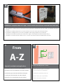
Tighten all bolts securely
• Apriete todos los pernos con seguridad
• Serrez tous les boulons solidement
• Ziehen Sie alle Schraubbolzen sicher fest
• Aperte todos os parafusos firmemente
• Stringa saldamente tutti i bulloni
Hang the Igloo Dome unit onto the wall mount
• Cuelgue la unidad Deputy2 sobre el montaje de la pared
• Accrochez l'unité Igloo Dome sur le bâti de mur
• Hängen Sie die Iglu-Haubemaßeinheit auf die Wandeinfassung
• Pendure a unidade da abóbada do Igloo na montagem da parede
• Appenda l'unità Igloo Dome sul supporto della parete
12
13
14
11
La pagina si sta caricando...

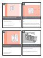
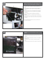
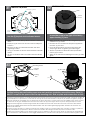
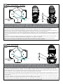
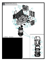
Route cables and connect as shown
• Encamine los cables y conecte como se muestra
• Conduisez les câbles et reliez comme montré
• Verlegen Sie Kabel und schließen Sie wie gezeigt an
• Distribua cabos e conecte-os como mostrado
• Diriga i cavi e colleghi come indicato
Connect wires as shown, use minimum of 14 AWG
• Conecte los alambres como se muestra, utilice el mínimo de AWG 14
• Reliez les fils comme montré, employez le minimum d'A.W.G. 14
• Schließen Sie Drähte wie gezeigt an, verwenden Sie Minimum von
AWG-Lehre 14
• Conecte fios como mostrado, use um mínimo de Calibre de diâmetro de
fios 14
• Colleghi i legare come indicato, usi un minimo dell'AWG 14
GND
N
L
GND
N
L
INPUT
OUTPUT
STEP 3:
COMPLETE ELECTRICAL CONNECTIONS
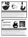
Route power and video cables through the water tight
feed (at the base of the unit)
• Encamine los cables de la energía y del vídeo a través de la
alimentación apretada del agua (en la base de la unidad)
• Conduisez les câbles de puissance et de vidéo par l'alimentation serrée
de l'eau (à la base de l'unité)
• Verlegen Sie Energien- und Videokabel durch die feste Zufuhr des
Wassers (an der Unterseite der Maßeinheit)
• Distribua cabos do poder e do vídeo através da alimentação
apertada da água (na base da unidade)
• Diriga i cavi del video e di potere attraverso l'alimentazione stretta
dell'acqua (alla base dell'unità)
20
19

Remove right side louver panel
• Quite el panel de la lumbrera del derecho
• Enlevez le panneau d'auvent de côté droit
• Entfernen Sie Luftschlitzverkleidung der rechten Seite
• Remova o painel da grelha do lado direito
• Rimuova il pannello della feritoia della parte di destra
Set louver aside
• Fije la lumbrera a un lado
• Placez l'auvent de côté
• Stellen Sie Luftschlitz beiseite ein
• Ajuste a grelha de lado
• Regoli la feritoia da parte
21
22

Initial liquid level should be between “High” and “Low”
markers
• El nivel líquido inicial debe estar entre “los marcadores altos” y “bajos”
• Le niveau liquide initial devrait être entre les « hauts » et « bas »
marqueurs
• Flüssiges zuerstniveau sollte zwischen „den hohen“ und „niedrigen“
Markierungen sein
• O nível líquido inicial deve estar entre “marcadores elevados” e
“baixos”
• Il livello liquido iniziale dovrebbe essere fra “gli alti„ ed indicatori “bassi„
This is what the typical path of illumination will look like with the setting at 30 degrees.
• Esto es lo que parecerá la trayectoria típica de la iluminación con el ajuste 30 grados.
• C'est ce qui ressemblera le chemin typique de l'illumination à avec l'arrangement 30 degrés.
• Dieses ist, was der typische Weg der Ablichtung wie mit der Einstellung bei 30 Grad aussieht.
• Este é o que o trajeto típico da iluminação olhará como com o ajuste em 30 graus.
• Ciò è che cosa il percorso tipico di illuminazione assomiglierà con alla regolazione 30 gradi
Remove cap and still reservoir with Propylene Glycol/
water mix. Use mix ratio specified or container (*)
• Quite el casquillo y aún el depósito con la mezcla del glicol/del agua
de propileno. Utilice el cociente de la mezcla especificado o el
envase
• Enlevez le chapeau et toujours le réservoir avec le mélange de
propylèneglycol/eau. Utilisez le rapport de mélange spécifique ou le
récipient
• Entfernen Sie Kappe und noch Vorratsbehälter mit Propylenglykol-/-
wassermischung. Benutzen Sie das spezifizierte Mischungsverhältnis
oder Behälter
• Remova o tampão e ainda o reservatório com a mistura do
glicol/água de Propylene. Use a relação da mistura especific ou o
recipiente
• Rimuova la protezione ed ancora il bacino idrico con la miscela del
glicol/acqua di propilene. Utilizzi il rapporto della miscela specificato o
il contenitore
* Refer to the Mechanical Operations section of the instructions for
proper mixture proportions
This is what the typical path of illumination will look like with the setting at 30 degrees.
• Esto es lo que parecerá la trayectoria típica de la iluminación con el ajuste 30 grados.
• C'est ce qui ressemblera le chemin typique de l'illumination à avec l'arrangement 30 degrés.
• Dieses ist, was der typische Weg der Ablichtung wie mit der Einstellung bei 30 Grad aussieht.
• Este é o que o trajeto típico da iluminação olhará como com o ajuste em 30 graus.
• Ciò è che cosa il percorso tipico di illuminazione assomiglierà con alla regolazione 30 gradi
24
23

Power up the unit by activating the “Primer” button as
shown to circulate coolant through system. Add
coolant after system stabilizes-if required (should be
between the “High” and “Low” marker.
• Accione para arriba la unidad activando el botón de la “cartilla”
como se muestra para circular el líquido refrigerador a través de
sistema. Agregue el líquido refrigerador después de sistema estabilizar-
si está requerido (debe estar entre “el marcador alto” y “bajo”.
• Mettez l'unité en actionnant le bouton de « amorce » comme montré
pour circuler le liquide réfrigérant par le système. Ajoutez le liquide
réfrigérant après système stabiliser-si requis (devrait être entre le « haut
» et « bas » marqueur.
• Treiben Sie oben die Maßeinheit an, indem Sie wie gezeigt den
„Zündkapsel“ Knopf aktivieren, um Kühlmittel durch System zu verteilen.
Fügen Sie Kühlmittel nach System hinzu, stabilisieren-wenn erfordert
(sollte zwischen der „hohen“ und „niedrigen“ Markierung sein.
• Pnha acima a unidade ativando a tecla da “primeira demão” como
mostrado para circular o líquido refrigerante através do sistema.
Adicione o líquido refrigerante após o sistema estabilizar-se exigido
(deve estar entre “o marcador elevado” e “baixo”.
• Alimenti in su l'unità attivando il tasto “dell'iniettore„ come indicato per
fare circolare il liquido refrigerante attraverso il sistema. Aggiunga il
liquido refrigerante dopo il sistema stabilizzare-se richiesto (dovrebbe
essere fra “l'alto„ ed indicatore “basso„.
This is what the typical path of illumination will look like with the setting at 30 degrees.
• Esto es lo que parecerá la trayectoria típica de la iluminación con el ajuste 30 grados.
• C'est ce qui ressemblera le chemin typique de l'illumination à avec l'arrangement 30 degrés.
• Dieses ist, was der typische Weg der Ablichtung wie mit der Einstellung bei 30 Grad aussieht.
• Este é o que o trajeto típico da iluminação olhará como com o ajuste em 30 graus.
• Ciò è che cosa il percorso tipico di illuminazione assomiglierà con alla regolazione 30 gradi
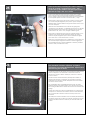
The air intake filters should be periodically checked.
They should be cleaned or replaced. To replace,
unfasten the nuts holding the filter frame. Replace and
remount using nuts as shown.
• Los filtros de la toma de aire deben ser comprobados periódicamente.
Deben ser limpiados o ser substituidos. Para substituir, desate la
tenencia nuts el marco del filtro. Substituya y remonte con tuercas
como se muestra.
• Les filtres d'entrée d'air devraient être périodiquement vérifiés. Ils
devraient être nettoyés ou remplacés. Pour remplacer, desserrez
l'exploitation nuts l'armature de filtre. Remplacez et remount à l'aide
des écrous comme montrés.
• Die Lufteintritfilter sollten regelmäßig überprüft werden. Sie sollten
gesäubert werden oder ersetzt werden. Um zu ersetzen, lösen Sie die
nuts Holding der Filterrahmen. Ersetzen Sie und remount mit Nüssen wie
gezeigt.
• Os filtros da entrada de ar devem periòdicamente ser verific. Devem
ser limpados ou substituído. Para substituir, desate a terra arrendada
nuts o frame do filtro. Substitua e remount usando porcas como
mostradas.
• I filtri dalla presa di aria dovrebbero essere controllati periodicamente.
Dovrebbero essere puliti o sostituiti. Per sostituire, sciolga la tenuta nuts
la struttura del filtro. Sostituisca e remount per mezzo dei dadi come
indicati.
This is what the typical path of illumination will look like with the setting at 30 degrees.
• Esto es lo que parecerá la trayectoria típica de la iluminación con el ajuste 30 grados.
• C'est ce qui ressemblera le chemin typique de l'illumination à avec l'arrangement 30 degrés.
• Dieses ist, was der typische Weg der Ablichtung wie mit der Einstellung bei 30 Grad aussieht.
• Este é o que o trajeto típico da iluminação olhará como com o ajuste em 30 graus.
• Ciò è che cosa il percorso tipico di illuminazione assomiglierà con alla regolazione 30 gradi
26
25

Mount louver panel(s)
• Los paneles de la lumbrera del montaje
• Panneaux d'auvent de bâti
• Einfassungsluftschlitzverkleidungen
• Painéis da grelha da montagem
• Pannelli della feritoia del supporto
17
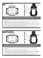
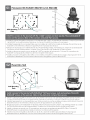
Install the camera to the mounting plate with (2) #10 screws and lock washers provided. Place (3)
#8x3/8” screws on the spacers and align the mounting slots. Slide on plate and camera then secure.
• Instale la cámara fotográfica a la placa de montaje con (2) los tornillos #10 y las arandelas de cerradura proporcionadas. Coloque los
tornillos de (3) del # 8x3/8"en los espaciadores y alinee las ranuras de montaje. Resbale en la placa y la cámara fotográfica entonces
seguras.
• Installez l'appareil-photo sur le plat de support avec (2) les vis #10 et les rondelles de freinage fournies. Placez les vis de (3) # de 8x3/8"
sur les entretoises et alignez les fentes de support. Glissez du plat et de l'appareil-photo puis bloqués.
• Bringen Sie die Kamera zur Montageplatte mit (2) den bereitgestellten Schrauben #10 und Federringen an. Setzen Sie (3) # 8x3/8"die
Schrauben auf die Distanzscheiben und richten Sie die Befestigungsschlitze aus. Schieben Sie auf die sichere Platte und Kamera dann.
• Instale a câmera à placa de montagem com (2) os parafusos #10 e as arruelas de fechamento fornecidas. Coloque os parafusos de
(3) # de 8x3/8"nos espaçadores e alinhe os entalhes de montagem. Deslize na placa e na câmera então seguras.
• Installi la macchina fotografica al giunto di supporto con (2) le viti #10 e le ranelle di bloccaggio fornite. Disponga le viti di 8x3/8"# di (3)
sui distanziatori ed allinei le scanalature di montaggio. Faccia scorrere sulla piastra e sulla macchina fotografica allora sicure.
2539 Mounting Plate
Mounting
Hole
Mounting
Hole
Axis 213
(26
mm
) 1"
(52
mm
) 2"
(13
mm
) ½"
Captive
Screw
(3) #8x3/8”
28
27

18
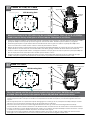
3026 Mounting
Plate
Mounting
Hole
Mounting
Hole
Mounting Hole
Axis 214
(52
mm
) 2"
Captive
Screw
(3) #8 x 3/8”
Install the camera to the mounting plate using (3) 3mm x 12mm bolts and lock washers. Place (3) #8x3/8”
screws on the spacers and line up the mounting slots. Slide plate in and secure.
• Instale la cámara fotográfica a la placa de montaje usando (3) los pernos de 3m m x de 12m m y las arandelas de cerradura.
Coloque los tornillos de (3) del # 8x3/8"en los espaciadores y alinee las ranuras de montaje. Resbale la placa adentro y
asegúrela.
• Installez l'appareil-photo sur le plat de support en utilisant (3) des boulons de 3mm x de 12mm et des rondelles de freinage.
Placez les vis de (3) # de 8x3/8"sur les entretoises et alignez les fentes de support. Glissez le plat dedans et le fixez.
• Bringen Sie die Kamera zur Montageplatte mit (3) 3mm x 12mm den Schraubbolzen und den Federringen an. Setzen Sie (3) #
8x3/8"die Schrauben auf die Distanzscheiben und richten Sie die Befestigungsschlitze aus. Schieben Sie Platte innen und sichern
Sie.
• Instale a câmera à placa de montagem usando (3) os parafusos de 3mm x de 12mm e as arruelas de fechamento. Coloque os
parafusos de (3) # de 8x3/8"nos espaçadores e alinhe-os acima dos entalhes de montagem. Deslize a placa dentro e fixe-a.
• Installi la macchina fotografica al giunto di supporto usando (3) i bulloni di 12mm x di 3mm e le ranelle di bloccaggio. Disponga
le viti di 8x3/8"# di (3) sui distanziatori ed allinei le scanalature di montaggio. Faccia scorrere la piastra dentro e fissi.
29
Install the camera to the mounting plate with (4) #8 screws and lock washers provided. Place (3) #8x3/8”
screws on the spacers and align the mounting slots. Slide on plate and camera then secure.
• Instale la cámara fotográfica a la placa de montaje con (4) los tornillos #8 y las arandelas de cerradura proporcionadas. Coloque los
tornillos de (3) del # 8x3/8"en los espaciadores y alinee las ranuras de montaje. Resbale en la placa y la cámara fotográfica entonces
seguras.
• Installez l'appareil-photo sur le plat de support avec (4) les vis #8 et les rondelles de freinage fournies. Placez les vis de (3) # de 8x3/8"
sur les entretoises et alignez les fentes de support. Glissez du plat et de l'appareil-photo puis bloqués.
• Bringen Sie die Kamera zur Montageplatte mit (4) den bereitgestellten Schrauben #8 und Federringen an. Setzen Sie (3) # 8x3/8"die
Schrauben auf die Distanzscheiben und richten Sie die Befestigungsschlitze aus. Schieben Sie auf die sichere Platte und Kamera dann.
• Instale a câmera à placa de montagem com (4) os parafusos #8 e as arruelas de fechamento fornecidas. Coloque os parafusos de
(3) # de 8x3/8"nos espaçadores e alinhe os entalhes de montagem. Deslize na placa e na câmera então seguras.
• Installi la macchina fotografica al giunto di supporto con (4) le viti #8 e le ranelle di bloccaggio fornite. Disponga le viti di 8x3/8"# di (3)
sui distanziatori ed allinei le scanalature di montaggio. Faccia scorrere sulla piastra e sulla macchina fotografica allora sicure.
Holes
Mounting
Holes
1"
1"
2"
Mounting
Axis 215
30
La pagina si sta caricando...

3mm
Screw
Power
Board
Connection
Module
20
This is what the typical path of illumination will look like with the setting at 30 degrees.
• Quite a tablero de energía situado dentro de la cubierta. Una el módulo de la conexión según lo demostrado. Una
a esta asamblea a la cubierta usando (1) "arandela del tornillo 6-32x3/8 y de la estrella.
• Enlevez carte d'alimentation situé à l'intérieur du logement. Attachez le module de raccordement comme montré.
Attachez cette assemblée au logement en utilisant (1) la "vis 6-32x3/8 et tenez le premier rôle la rondelle.
• Entfernen Sie das Energie Brett, das innerhalb des Gehäuses befunden wird. Bringen Sie das Anschlußmodul an, wie
gezeigt. Bringen Sie diese Versammlung zum Gehäuse mit (1) "Schraube 6-32x3/8 und Sternunterlegscheibe an.
• Remova a placa de poder situada dentro da carcaça. Una o módulo da conexão como mostrado. Una este
conjunto à carcaça usando (1) do "arruela parafuso 6-32x3/8 e da estrela.
• Rimuova il bordo di alimentazione situato all'interno dell'alloggiamento. Fissi il modulo del collegamento come
indicato. Fissi questo complessivo all'alloggiamento usando (1) "rondella della vite 6-32x3/8 e della stella.
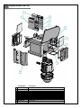
Remove the power board located inside the housing. Attach the connection module as shown.
Attach this assembly to the housing using (1) 6-32x3/8” screw and star washer.
This is what the typical path of illumination will look like with the setting at 30 degrees.
• Termine el cableado a la cámara fotográfica. Una el montaje de la cámara fotográfica a la cubierta resbalando
(3) las ranuras abiertas del tornillo sobre los tornillos en la cubierta; apriete los sujetadores en el soporte.
• Accomplissez le câblage à l'appareil-photo. Attachez l'appareil-photo au logement en glissant (3) les fentes
ouvertes de vis au-dessus des vis dans le logement ; serrez les attaches sur la parenthèse.
• Führen Sie die Verdrahtung zur Kamera durch. Bringen Sie die Kamera zum Gehäuse an, indem Sie die (3) geöffne-
ten Schraube Schlitze über den Schrauben im Gehäuse schieben; ziehen Sie die Befestiger am Haltewinkel fest.
• Termine a fiação à câmera. Una o conjunto da câmera à carcaça deslizando (3) os entalhes abertos do parafuso
sobre os parafusos na carcaça; aperte os prendedores no suporte.
• Completi i collegamenti alla macchina fotografica. Fissi il complessivo della macchina fotografica all'alloggiamento
facendo scorrere (3) le scanalature aperte della vite sopra le viti nell'alloggiamento; stringa i fermi sulla staffa.
CONTROL
RJ45 Ethernet Connector
ALARMS
1 Alarm 1 Blue
2 Alarm 2 Violet
3 Alarm 3 Gray
4 Common White
POWER
1 Camera Power (24VAC) Red
2 Camera Power (24VAC) Orange
Captive
Screw
Open Screw
Slots
Cable
Ties
Complete the wiring to camera. Attach the camera assembly to the housing by sliding the (3)
open screw slots over the screws in the housing; tighten the fasteners on the bracket.
34
35

Axis 233D
Use the holes indicated above to mount
the camera.
• Utilice los agujeros indicados arriba para montar la
cámara fotográfica.
• Employez les trous indiqués ci-dessus pour monter
l'appareil-photo.
• Benutzen Sie die Bohrungen, die oben angezeigt
werden, um die Kamera anzubringen.
• Use os furos indicados acima para montar a
câmera.
• Usi i fori indicati sopra per montare la macchina
fotografica.
Mounting Hole
Mounting Hole
Disconnect the orange, red, and black wires. Remove the
power board in the housing by loosening screws on the
terminal block and the (4) machine screws.
• Desconecte los alambres anaranjados, rojos, y negros. Quite a tablero de
energía en la cubierta aflojando los tornillos en el bloque de terminales y (4)
los tornillos de la máquina.
• Débranchez les fils oranges, rouges, et noirs. Enlevez carte d'alimentation
dans le logement en desserrant des vis sur le TB et (4) les vis de machine.
• Trennen Sie die orange, roten und schwarzen Leitungen. Entfernen Sie das
Energie Brett im Gehäuse, indem Sie Schrauben am Klemmenblock und an
den (4) Maschine Schrauben lösen.
• Desconecte os fios alaranjados, vermelhos, e pretos. Remova a placa de
poder na carcaça afrouxando os parafusos no bloco terminal e (4) nos
parafusos da máquina.
• Stacchi i legare arancioni, rossi e neri. Rimuova il bordo di alimentazione
nell'alloggiamento allentando le viti sul blocchetto terminali e (4) sulle viti
della macchina.
Power
Board
Now remove the mounting bracket and attach (4) 1/2” spacers (located in the packet that came
with the housing) to the base bracket.
• Ahora quite el soporte de montaje y una (4) los espaciadores del 1/2"(situados en el paquete que vino con la cubierta)
al soporte bajo.
• Maintenant enlevez le support et attachez (4) les entretoises de 1/2"(situées dans le paquet qui est venu avec le
logement) à la parenthèse basse.
• Jetzt entfernen Sie die Schienenplatte und bringen Sie (4) die 1/2"Distanzscheiben (gelegen im Paket, das mit dem
Gehäuse kam), zum niedrigen Haltewinkel an.
• Agora remova o suporte de montagem e una (4) os espaçadores de 1/2"(situados no pacote que veio com a
carcaça) ao suporte baixo.
• Ora rimuova il supporto di attacco e fissi (4) i distanziatori di 1/2"(situati nel pacchetto che è venuto con
l'alloggiamento) alla staffa bassa.
Mounting
Bracket
½"
36
37
38

Quick Release
Plate
Base Bracket
Camera
Bracket
Additional
Spacers
Keyhole
Slots
This is what the typical path of illumination will look like with the setting at 30 degrees.
• Monte el soporte de la cámara fotográfica del eje 233D y la placa rápida del lanzamiento usando los espaciadores
adicionales del paquete del hardware.
• Montez la parenthèse d'appareil-photo de l'axe 233D et le plat rapide de dégagement en utilisant les entretoises
additionnelles du paquet de matériel.
• Bringen Sie den Mittellinie 233D Kamerahaltewinkel und schnelle die Freigabeplatte mit den zusätzlichen Distanzs-
cheiben vom Kleinteilpaket an.
• Monte o suporte da câmera da linha central 233D e a placa rápida da liberação usando os espaçadores adicio-
nais do pacote da ferragem.
• Monti la staffa della macchina fotografica di asse 233D e la piastra rapida del rilascio usando i distanziatori supple-
mentari dal pacchetto dei fissaggi.
Mount the Axis 233D camera bracket and quick release plate using the additional spacers from
the hardware packet.
This is what the typical path of illumination will look like with the setting at 30 degrees.
• Coloque la placa rápida del lanzamiento sobre el fondo de la cámara fotográfica. Alinee los tornillos de fijación de la cámara fotográfica y las
ranuras del ojo de la cerradura. Resbale la cámara fotográfica dentro de las ranuras del ojo de la cerradura hasta que los botones de fijación
golpean el extremo, y apriete el tornillo de pulgar.
• Placez le plat rapide de dégagement sur le fond de l'appareil-photo. Alignez les vis de blocage d'appareil-photo et les fentes de trou de la
serrure. Glissez l'appareil-photo dans les fentes de trou de la serrure jusqu'à ce que les boutons de fermeture frappent l'extrémité, et serrez la vis de
pouce.
• Setzen Sie schnelle Freigabeplatte auf der Unterseite der Kamera. Richten Sie die Sicherungsschrauben der Kamera und die Schlüssellochschlitze
aus. Schieben Sie Kamera in die Schlüssellochschlitze, bis die verriegelntasten das Ende schlagen, und ziehen Sie die Rändelschraube fest.
• Coloque a placa rápida da liberação no fundo da câmera. Alinhe os parafusos travando da câmera e os entalhes do buraco da fechadura.
Deslize a câmera nos entalhes do buraco da fechadura até que as teclas travando batam a extremidade, e aperte o parafuso de polegar.
• Disponga la piastra rapida del rilascio sulla parte inferiore della macchina fotografica. Allinei le viti di bloccaggio della macchina fotografica e le
scanalature del buco della serratura. Faccia scorrere la macchina fotografica nelle scanalature del buco della serratura fino a che i tasti di
bloccaggio non colpiscano l'estremità e stringa la vite di pollice.
Place quick release plate onto the bottom of the camera. Align the camera locking screws and the keyhole
slots. Slide camera into the keyhole slots until the locking buttons hit the end, and tighten the Thumb screw.
Keyhole Slots
Thumb Screw
Locking Screw
39
40
La pagina si sta caricando...
La pagina si sta caricando...

2539 Mounting Plate
Mounting Hole
Mounting Hole
Elmo PTC-201
(52
mm
) 2"
(13
mm
) ½"
Place the camera onto the quick release bracket using the (4) metric 3M Phillips head screws
provided. Place the screws on the spacers. Slide on the plate and camera then secure.
Captive
Screw
•
Coloque la cámara fotográfica sobre el soporte rápido del lanzamiento usando (4) los tornillos principales los 3M Phillips
métricos proporcionados. Coloque los tornillos en los espaciadores. Resbale en la placa y la cámara fotográfica entonces
seguras.
•
Placez l'appareil-photo sur la parenthèse rapide de dégagement à l'aide (4) des vis principales 3M Phillips métriques fournies.
Placez les vis sur les entretoises. Glissez du plat et de l'appareil-photo puis bloqués.
•
Setzen Sie die Kamera auf dem schnellen Freigabehaltewinkel mit den (4) metrischen 3M bereitgestellten Kreuzkopf-
hauptschrauben. Setzen Sie die Schrauben auf die Distanzscheiben. Schieben Sie auf die sichere Platte und die Kamera dann.
•
Coloque a câmera no suporte rápido da liberação usando (4) os parafusos principais 3M Phillips métricos fornecidos.
Coloque os parafusos nos espaçadores. Deslize na placa e na câmera então seguras.
•
Disponga la macchina fotografica sulla staffa rapida del rilascio per mezzo (4) delle viti cape "phillips" 3M metriche fornite.
Disponga le viti sui distanziatori. Faccia scorrere sulla piastra e sulla macchina fotografica allora sicure.
27
2539 Mounting Plate
Mounting Hole
Mounting Hole
Elmo PTC-400C
(52
mm
) 2"
(13
mm
) ½"
Attach quick release bracket to mounting plate using (4) #8 screws and star washer. Complete
assembly as shown, then secure camera to the quick release plate.
(26
mm
) 1"
• Una el soporte rápido del lanzamiento a la placa de montaje usando (4) los tornillos #8 y la arandela de la estrella.
Termine a asamblea como cámara fotográfica demostrada, después segura a la placa rápida del lanzamiento.
• Attachez la parenthèse rapide de dégagement au plat de support à l'aide (4) des vis #8 et tenez le premier rôle la
rondelle. Accomplissez l'assemblée en tant qu'appareil-photo montré et puis bloqué au plat rapide de dégagement.
• Bringen Sie schnellen Freigabehaltewinkel zur Montageplatte mit (4) Schrauben #8 und Sternunterlegscheibe an. Führen
Sie Versammlung als gezeigte, dann sichere Kamera zur schnellen Freigabeplatte durch.
• Una o suporte rápido da liberação à placa de montagem usando (4) os parafusos #8 e a arruela da estrela. Termine o
conjunto como a câmera mostrada, a seguir segura à placa rápida da liberação.
• Fissi la staffa rapida del rilascio al giunto di supporto usando (4) le viti #8 e la rondella della stella. Completi il complessivo
come macchina fotografica indicata e quindi sicura alla piastra rapida del rilascio.
Quick release
plate
45
46

28
2539 Mounting Plate
Mounting Hole
Mounting Hole
Elmo PTC-401
(52
mm
) 2"
Attach quick release bracket to mounting plate using (4) #8 screws and star washer. Complete
assembly as shown, then secure camera to the quick release plate.
(26
mm
) 1"
Captive
Screw
• Una el soporte rápido del lanzamiento a la placa de montaje usando (4) los tornillos #8 y la arandela de la estrella.
Termine a asamblea como cámara fotográfica demostrada, después segura a la placa rápida del lanzamiento.
• Attachez la parenthèse rapide de dégagement au plat de support à l'aide (4) des vis #8 et tenez le premier rôle la
rondelle. Accomplissez l'assemblée en tant qu'appareil-photo montré et puis bloqué au plat rapide de dégagement.
• Bringen Sie schnellen Freigabehaltewinkel zur Montageplatte mit (4) Schrauben #8 und Sternunterlegscheibe an. Führen
Sie Versammlung als gezeigte, dann sichere Kamera zur schnellen Freigabeplatte durch.
• Una o suporte rápido da liberação à placa de montagem usando (4) os parafusos #8 e a arruela da estrela. Termine o
conjunto como a câmera mostrada, a seguir segura à placa rápida da liberação.
• Fissi la staffa rapida del rilascio al giunto di supporto usando (4) le viti #8 e la rondella della stella. Completi il comples-
sivo come macchina fotografica indicata e quindi sicura alla piastra rapida del rilascio.
Quick release
plate
29
2539 Mounting Plate
Mounting Hole
JVC VN-C30U
(52
mm
) 2"
Remove the camera plate and mount to the bracket using the (3) metric 3M Phillips head screws.
Reattach plate back to the camera. Place the screws on the spacers. Secure the plate and camera.
(13
mm
) ½"
• Quite la placa y el montaje de la cámara fotográfica al soporte usando (3) los tornillos principales los 3M Phillips métricos. Reate
la placa de nuevo a la cámara fotográfica. Coloque los tornillos en los espaciadores. Asegure la placa y la cámara fotográfica.
• Enlevez le plat et le bâti d'appareil-photo sur la parenthèse à l'aide (3) des vis principales 3M Phillips métriques. Rattachez le plat
de nouveau à l'appareil-photo. Placez les vis sur les entretoises. Fixez le plat et l'appareil-photo.
• Entfernen Sie die Kameraplatte und -einfassung zum Haltewinkel mit den (3) metrischen 3M Kreuzkopfhauptschrauben. Befesti-
gen Sie Platte zurück zu der Kamera wieder. Setzen Sie die Schrauben auf die Distanzscheiben. Sichern Sie die Platte und die
Kamera.
• Remova a placa e a montagem da câmera ao suporte usando (3) os parafusos principais 3M Phillips métricos. Reate a parte
traseira da placa à câmera. Coloque os parafusos nos espaçadores. Fixe a placa e a câmera.
• Rimuova la piastra ed il supporto della macchina fotografica alla staffa per mezzo (3) delle viti cape "phillips" 3M metriche.
Riattacci la piastra di nuovo alla macchina fotografica. Disponga le viti sui distanziatori. Fissi la piastra e la macchina fotografica.
47
48

30
2630 Mounting
Plate
Mounting
Hole
JVC VN-C625U / TK-625U
Remove the cover and detach bracket. Attach (4) 1” spacers to the 2630 mounting plate and (4) to
the main bracket. Place (3) 8x32x3/8” Phillips screws onto the spacers. Secure plate and camera.
(26
mm
) 1"
(26
mm
) 1"
• Quite la cubierta y separe el soporte. Una (4) los espaciadores del 1"a la placa de montaje 2630 y (4) al soporte principal.
Coloque (3) los tornillos Phillips del 8x32x3/8"sobre los espaciadores. Asegure la placa y la cámara fotográfica.
• Enlevez la couverture et détachez la parenthèse. Attachez (4) les entretoises de 1"au plat de support 2630 et (4) à la paren-
thèse principale. Placez (3) les vis Phillips de 8x32x3/8"sur les entretoises. Fixez le plat et l'appareil-photo.
• Entfernen Sie die Abdeckung und trennen Sie Haltewinkel ab. Bringen Sie (4) die 1"Distanzscheiben zur 2630 Montageplatte und
(4) zum Haupthaltewinkel an. Setzen Sie (3) 8x32x3/8"die Kreuzkopfschrauben auf den Distanzscheiben. Sichern Sie Platte und
Kamera.
.
•
Remova a tampa e destaque o suporte. Una (4) espaçadores de 1"à placa de montagem 2630 e (4) ao suporte principal.
Coloque (3) os parafusos Phillips de 8x32x3/8"nos espaçadores. Fixe a placa e a câmera.
• Rimuova la copertura e stacchi la staffa. Fissi (4) i distanziatori di 1"al giunto di supporto 2630 e (4) alla staffa principale.
Disponga (3) le viti "phillips" di 8x32x3/8"sui distanziatori. Fissi la piastra e la macchina fotografica.
31
2630 Mounting
Plate
Mounting
Hole
JVC VN-C655U
Place the camera on the bracket with the (4) phillips head screws. Use (4) 1” spacers and (4) 1/2”
spacers provided. Place the screws on the spacers. Slide on the plate and camera then secure.
(26
mm
) 1"
(13
mm
) ½"
• Coloque la cámara fotográfica en el soporte con (4) los tornillos principales Phillips. Utilice (4) los espaciadores del 1"y (4) 1/2"
spacers proporcionados. Coloque los tornillos en los espaciadores. Resbale en la placa y la cámara fotográfica entonces seguras.
• Placez l'appareil-photo sur la parenthèse avec (4) les vis principales Phillips. Employez (4) les entretoises de 1"et (4) le 1/2" spacers
fournis. Placez les vis sur les entretoises. Glissez du plat et de l'appareil-photo puis bloqués.
• Setzen Sie die Kamera am Haltewinkel mit den (4) Kreuzkopfhauptschrauben. Verwenden Sie (4) die 1"Distanzscheiben und (4) 1/2"
spacers, die bereitgestellt werden. Setzen Sie die Schrauben auf die Distanzscheiben. Schieben Sie auf die sichere Platte und die
Kamera dann.
• Coloque a câmera no suporte com (4) os parafusos principais Phillips. Use (4) os espaçadores de 1"e (4) o 1/2"spacers fornecidos.
Coloque os parafusos nos espaçadores. Deslize na placa e na câmera então seguras.
• Disponga la macchina fotografica sulla staffa con (4) le viti cape "phillips". Usi (4) i distanziatori di 1"e (4) 1/2"spacers forniti. Disponga
le viti sui distanziatori. Faccia scorrere sulla piastra e sulla macchina fotografica allora sicure.
49
50
La pagina si sta caricando...

34
2539 Mounting
Plate
Mounting Hole
Mounting Hole
Sony SNCRZ25
Attach bracket with (1) 1/4x20 bolt, washer and lock washer and (2) 3mm x 8mm Phillip head screws
and lockwashers. Place the screws on the spacers. Slide on the plate and camera then secure.
(26
mm
) 1"
• Instale la cámara fotográfica al soporte con (3) los tornillos, las tuercas y las arandelas principales el 8x32x.5"planos.
Coloque (3) 8x32x3/8"screws en los espaciadores. Resbale en la placa y la cámara fotográfica entonces seguras.
• Installez l'appareil-photo sur la parenthèse avec (3) les vis, les écrous et les rondelles principaux 8x32x.5"plats. Placez (3)
8x32x3/8"screws sur les entretoises. Glissez du plat et de l'appareil-photo puis bloqués.
• Bringen Sie Kamera zum Haltewinkel mit (3) 8x32x.5"flachen Hauptschrauben, Nüssen und Unterlegscheiben an. Setzen
Sie (3) 8x32x3/8"screws auf die Distanzscheiben. Schieben Sie auf die sichere Platte und die Kamera dann.
• Instale a câmera ao suporte com (3) os parafusos, as porcas e as arruelas principais 8x32x.5"lisos. Coloque (3) 8x32x3/8"
screws nos espaçadores. Deslize na placa e na câmera então seguras.
• Installi la macchina fotografica alla staffa con (3) le viti, i dadi e le rondelle capi piani 8x32x.5". Disponga (3) 8x32x3/8"
screws sui distanziatori. Faccia scorrere sulla piastra e sulla macchina fotografica allora sicure.
35
2539 Mounting
Plate
Mounting Hole
Sony SNCRZ30
Attach bracket with (1) 1/4x20 bolt, washer and lock washer. Place (3) 8x32x3/8”screws on the
spacers. Slide on the plate and camera then secure.
(52
mm
) 2"
• Una el soporte con (1) el perno 1/4x20, la arandela y la arandela de cerradura. Coloque (3) 8x32x3/8" screws en los
espaciadores. Resbale en la placa y la cámara fotográfica entonces seguras.
• Attachez la parenthèse avec (1) le boulon 1/4x20, la rondelle et la rondelle de freinage. Placez (3) 8x32x3/8" screws sur
les entretoises. Glissez du plat et de l'appareil-photo puis bloqués.
• Bringen Sie Haltewinkel mit (1) Schraubbolzen 1/4x20, Unterlegscheibe und Federring an. Setzen Sie (3) 8x32x3/8" screws
auf die Distanzscheiben. Schieben Sie auf die sichere Platte und die Kamera dann.
• Una o suporte com (1) parafuso 1/4x20, arruela e arruela de fechamento. Coloque (3) 8x32x3/8" screws nos espaça-
dores. Deslize na placa e na câmera então seguras.
• Fissi la staffa con (1) il bullone 1/4x20, la rondella e la ranella di bloccaggio. Disponga (3) 8x32x3/8" screws sui distanzia-
tori. Faccia scorrere sulla piastra e sulla macchina fotografica allora sicure.
53
54
La pagina si sta caricando...
La pagina si sta caricando...
La pagina si sta caricando...
La pagina si sta caricando...
-
 1
1
-
 2
2
-
 3
3
-
 4
4
-
 5
5
-
 6
6
-
 7
7
-
 8
8
-
 9
9
-
 10
10
-
 11
11
-
 12
12
-
 13
13
-
 14
14
-
 15
15
-
 16
16
-
 17
17
-
 18
18
-
 19
19
-
 20
20
-
 21
21
-
 22
22
-
 23
23
-
 24
24
-
 25
25
-
 26
26
-
 27
27
-
 28
28
-
 29
29
-
 30
30
-
 31
31


Moog Videolarm IGDW75C1N Istruzioni per l'uso
- Categoria
- Accessori per telecamere di sicurezza
- Tipo
- Istruzioni per l'uso
- Questo manuale è adatto anche per
in altre lingue
Documenti correlati
-
Moog Videolarm ISM75TN Istruzioni per l'uso
-
-
-
-
-
-
-
Altri documenti
-
Moog Deputy2 Istruzioni per l'uso
-
Axis 25733 Manuale utente
-
-
-
-
-
Next Level Racing Flight Simulator Manuale utente
-
 Neomounts WL95-900BL16 Manuale utente
