NEC MultiSync® LCD1550X Manuale del proprietario
- Categoria
- TV
- Tipo
- Manuale del proprietario
Questo manuale è adatto anche per

MultiSync LCD1550X
User’s Manual
UÏivatelská pfiíruãka
Bedienerhandbuch
δηγίες ρήσης
Manual del usuario
Manuel Utilisateur
Manuale utente
Gebruikershandleiding
Podr´cznik u˝ytkownika
Руководство пользователя
Kullan∂c∂ Klavuzu
00Cover_all.p65 28/8/01, 2:37 pm1

00Cover_all.p65 28/8/01, 2:37 pm2

Declaration
Declaration of the Manufacturer
We hereby certify that the colour monitor
MultiSync LCD1550X (LCD1550X)
is in compliance with
Council Directive 73/23/EEC:
– EN 60950
Council Directive 89/336/EEC:
– EN 55022
– EN 61000-3-2
– EN 61000-3-3
– EN 55024
and marked with
NEC-Mitsubishi Electric Visual Systems, Corp.
MS Shibaura Bldg., 13-23,
Shibaura 4-chome,
Minato-Ku, Tokyo 108-0023, Japan
00Cover_all.p65 2/10/01, 9:31 am3

TCO’99
This is a translation of the original English TCO'99 document.
MultiSync LCD1550X (LCD1550X)
Congratulations! You have just purchased a TCO’99
approved and labeled product! Your choice has
provided you with a product developed for
professional use. Your purchase has also contributed
to reducing the burden on the environment and also
to the further development of environmentally
adapted electronics products.
Why do we have environmentally labelled computers?
In many countries, environmental labelling has become an established
method for encouraging the adaptation of goods and services to the
environment. The main problem, as far as computers and other
electronics equipment are concerned, is that environmentally harmful
substances are used both in the products and during the manufacturing.
Since it has not been possible for the majority of electronics equipment
to be recycled in a satisfactory way, most of these potentially damaging
substances sooner or later enter Nature.
There are also other characteristics of a computer, such as energy
consumption levels, that are important from the viewpoints of both the
work (Internal) and natural (external) environments. Since all methods of
conventional electricity generation have a negative effect on the
environment (acidic and climate-influencing emissions, radioactive
waste, etc.), it is vital to conserve energy. Electronics equipment in
offices consume an enormous amount of energy since they are often left
running continuously.
What does labelling involve?
This product meets the requirements for the TCO’99 scheme which
provides for international and environmental labelling of personal
computers. The labelling scheme was developed as a joint effort by the
TCO (The Swedish Confederation of Professional Employees), Svenska
Naturskyddsforeningen (The Swedish Society for Nature Conservation)
and Statens Energimyndighet (The Swedish National Energy
Administration).
00Cover_all.p65 28/8/01, 2:37 pm4

The requirements cover a wide range of issues: environment,
ergonomics, usability, emission of electrical and magnetic fields, energy
consumption and electrical and fire safety.
The environmental demands concern restrictions on the presence and
use of heavy metals, brominated and chlorinated flame retardants,
CFCs (freons) and chlorinated solvents, among other things. The
product must be prepared for recycling and the manufacturer is obliged
to have an environmental plan which must be adhered to in each
country where the company implements its operational policy. The
energy requirements include a demand that the computer and/or
display, after a certain period of inactivity, shall reduce its power
consumption to a lower level in one or more stages. The length of time
to reactivate the computer shall be reasonable for the user.
Labelled products must meet strict environmental demands, for
example, in respect of the reduction of electric and magnetic fields,
physical and visual ergonomics and good usability.
Environmental Requirements
Flame retardants
Flame retardants are present in printed circuit boards, cables, wires,
casings and housings. In turn, they delay the spread of fire. Up to thirty
percent of the plastic in a computer casing can consist of flame
retardant substances. Most flame retardants contain bromine or chloride
and these are related to another group of environmental toxins, PCBs,
which are suspected to give rise to severe health effects, including
reproductive damage in fisheating birds and mammals, due to the
bioaccumulative* processes. Flame retardants have been found in
human blood and researchers fear that disturbances in foetus
development may occur.
TCO’99 demand requires that plastic components weighing more than
25 grams must not contain flame retardants with organically bound
chlorine and bromine. Flame retardants are allowed in the printed circuit
boards since no substitutes are available.
Lead**
Lead can be found in picture tubes, display screens, solders and
capacitors. Lead damages the nervous system and in higher doses,
causes lead poisoning.
TCO’99 requirement permits the inclusion of lead since no replacement
has yet been developed.
00Cover_all.p65 28/8/01, 2:37 pm5

Cadmium**
Cadmium is present in rechargeable batteries and in the
colourgenerating layers of certain computer displays. Cadmium
damages the nervous system and is toxic in high doses.
TCO’99 requirement states that batteries, the colourgenerating layers of
display screens and the electrical or electronics components must not
contain any cadmium.
Mercury**
Mercury is sometimes found in batteries, relays and switches, Mercury
damages the nervous system and is toxic in high doses.
TCO’99 requirement states that batteries may not contain any Mercury.
It also demands that no mercury is present in any of the electrical or
electronics components associated with the display unit.
CFCs (freons)
CFCs (freons) are sometimes used for washing printed circuit boards.
CFCs break down ozone and thereby damage the ozone layer in the
stratosphere, causing increased reception on Earth of ultraviolet light
with consequent increased risks of skin cancer (malignant melanoma).
The relevant TCO’99 requirement; Neither CFCs nor HCFCs may be
used during the manufacturing and assembly of the product or its
packaging.
* Bio-accumulative is defined as substances which accumulate within
living organisms.
** Lead, Cadmium and Mercury are heavy metals which are
Bioaccumulative.
To obtain complete information on the environmental criteria document,
order from:
TCO Development Unit
SE-114 94 Stockholm
SWEDEN
FAX Number: +46 8 782 92 07
E-mail (Internet): development@tco.se
You may also obtain current information on TCO’99 approved and
labelled products by visiting their website at:
http://www.tco-info.com/
00Cover_all.p65 28/8/01, 2:37 pm6

English
âesky
Deutsch
Ελληνικά
Español
Français
Italiano
Nederlands
Polski
Русский
Türkçe
01b_XChapterOpener 28/8/01, 2:37 pm1

01b_XChapterOpener 28/8/01, 2:37 pm2

English-1
English
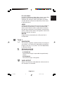
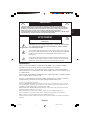
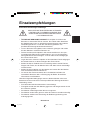
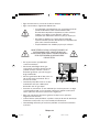
TO PREVENT FIRE OR SHOCK HAZARDS, DO NOT EXPOSE THIS UNIT TO RAIN
OR MOISTURE. ALSO, DO NOT USE THIS UNIT’S POLARIZED PLUG WITH AN
EXTENSION CORD RECEPTACLE OR OTHER OUTLETS UNLESS THE PRONGS
CAN BE FULLY INSERTED.
REFRAIN FROM OPENING THE CABINET AS THERE ARE HIGH VOLTAGE
COMPONENTS INSIDE. REFER SERVICING TO QUALIFIED SERVICE PERSONNEL.
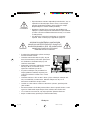
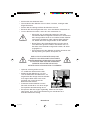
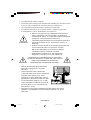
CAUTION
TO REDUCE THE RISK OF ELECTRIC SHOCK, DO NOT REMOVE COVER
(OR BACK). NO USER SERVICEABLE PARTS INSIDE. REFER SERVICING
TO QUALIFIED SERVICE PERSONNEL.
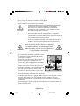
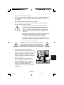
This symbol warns user that uninsulated voltage within the unit may have
sufficient magnitude to cause electric shock. Therefore, it is dangerous to make
any kind of contact with any part inside this unit.
This symbol alerts the user that important literature concerning the operation
and maintenance of this unit has been included. Therefore, it should be read
carefully in order to avoid any problems.
CAUTION
WARNING
RISK OF ELECTRIC SHOCK • DO NOT OPEN
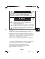
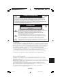
Caution:
When operating the MultiSync LCD1550X (LCD1550X) with a 220-240V AC power
source in Europe, use the power cord provided with the monitor.
In the UK, a BS approved power cord with a moulded plug has a Black (five Amps) fuse
installed for use with this equipment. If a power cord is not supplied with this equipment
please contact your supplier.
When operating the MultiSync LCD1550X with a 220-240V AC power source in
Australia, use the power cord provided with the monitor.
For all other cases, use a power cord that matches the AC voltage of the power outlet
and has been approved by and complies with the safety standard of your particular
country.
ENERGYSTA R is a U.S. trademark.
As an ENERGYSTA R
®
Partner, NEC-Mitsubishi Electronics Display of America, Inc. has
determined that this product meets the ENERGYSTA R guidelines for energy efficiency. The
ENERGYSTA R emblem does not represent EPA endorsement of any product or service.
IBM PC/XT/AT, PS/2, MCGA, VGA, 8514/A and XGA are registered trademarks of
International Business Machines Corporation.
Apple and Macintosh are registered trademarks of Apple Computer Inc.
Microsoft and Windows are registered trademarks of the Microsoft Corporation.
NEC is a registered trademark of NEC Corporation.
All other trademarks or registered trademarks are property of their respective owners.
01b_English 28/8/01, 2:37 pm1

English-2
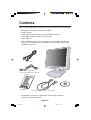
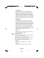
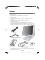
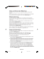
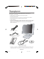
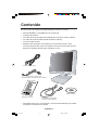
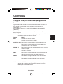
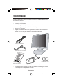
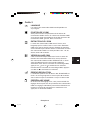
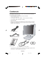
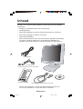
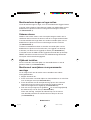
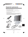
Contents
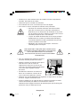
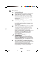
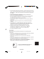
Your new NEC MultiSync LCD monitor box* should contain the following:
• MultiSync LCD1550X
monitor with tilt base
•Power Cord(s)
• Video Signal Cable (15-pin mini D-SUB male to DVI-A)
• Video Signal Cable (DVI-D to DVI-D Cable)
• User’s Manual
• NEC LCD Setup Software, Pivot Software, User’s Manual and other
helpful files. To see the User‘s Manual, Acrobat Reader 4.0 must be
installed on your PC.
* Remember to save your original box and packing material to
transport or ship the monitor.
User’s Manual
Software CD
Video Signal Cable (DVI-D to DVI-D Cable)
Video Signal Cable
(15-pin mini D-SUB male to DVI-A)
Power Cord(s)
01b_English 28/8/01, 2:37 pm2

English-3
English
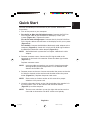
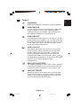
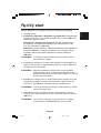
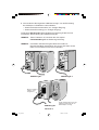
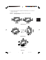
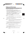
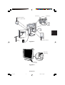
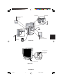
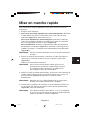
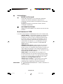
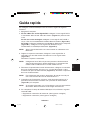
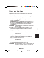
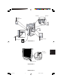
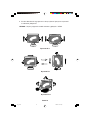
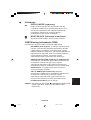
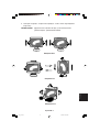
Quick Start
To attach the MultiSync LCD monitor to your system, follow these
instructions:
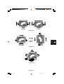
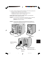
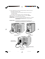
1. Turn off the power to your computer.
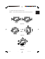
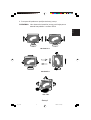
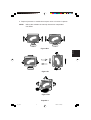
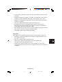
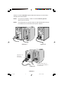
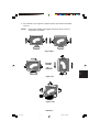
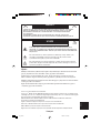
2. For the PC or Mac with DVI digital output: Connect the DVI-D to
DVI-D signal cable to the connector of the display card in your
system (Figure A.1). Tighten all screws.
For the PC with Analog output: Connect the 15-pin mini D-SUB to
DVI-A signal cable to the connector of the display card in your system
(Figure A.2).
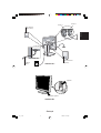
For the Mac: Connect the MultiSync Macintosh cable adapter to the
computer (Figure B.1). Attach the 15-pin mini D-SUB signal cable to
the MultiSync Macintosh cable adapter (Figure B.1).
NOTE: Some Macintosh systems do not require a Macintosh cable
adapter.
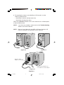
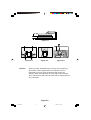
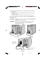
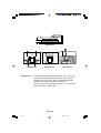
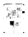
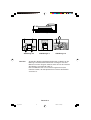
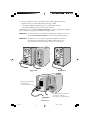
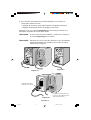
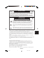
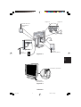
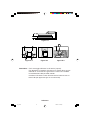
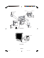
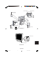
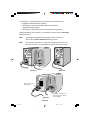
3. Remove connector cover. Connect the DVI signal cable to the
connector on the back of the monitor. Place the video signal cable
(Figure C.1).
Replace connector cover.
NOTE: Incorrect cable connections may result in irregular operation,
damage display quality/components of LCD module and/or
shorten the module’s life.
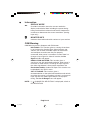
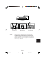
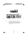
4. Remove power cord cover. Connect one end of the power cord to the
AC inlet on the back of the monitor and the other end to the power
outlet (Figure D.1). Replace the power cord cover.
NOTE: Please refer to Caution section of this manual for proper
selection of AC power cord.
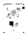
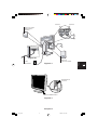
5. Check the Vacation Switch on the right hand side of the monitor is in
the ON position. Turn on the monitor with the Power Button
(Figure E.1) and the computer.
NOTE: There are two switches: one on the right side and one on the
front side of the monitor. DO NOT switch on/off quickly.
01b_English 28/8/01, 2:37 pm3

English-4
6. To complete the setup of your MultiSync LCD monitor, use the
following OSM controls:
•Auto Adjust Contrast (Analog input only)
•Auto Adjust (Analog input only)
Refer to the Controls section of this User’s Manual for a full description
of these OSM controls.
NOTE: If you have any problems, please refer to the Troubleshooting
section of this User’s Manual.
NOTE: Refer to User’s Manual in the NEC LCD Setup Software CD
case for installation and operation of this software.
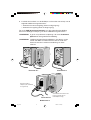
Figure B.1
Macintosh Cable
Adapter (not included)
Macintosh G3 and G4 do not
need a Macintosh cable adapter
Figure A.1
Figure A.2
01b_English 28/8/01, 2:37 pm4

English-5
English
Figure D.1
Figure E.1
Figure C.1
Input1
Input2
Vacation Switch
Power Button
Power Cord
Cover (left)
Connector
Cover (right)
Power Cord
01b_English 28/8/01, 2:37 pm5

English-6
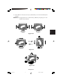
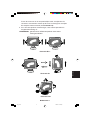
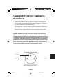
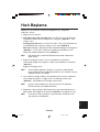
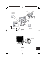
Raise and Lower Monitor Screen
The monitor may be raised or lowered in either Portrait or
Landscape mode.
To raise or lower screen, place hands on each side of the monitor and
lift or lower to the desired height (Figure RL.1).
Screen Rotation
Before rotating, the screen must be raised to the highest level to avoid
knocking the screen on the desk or pinching your fingers.
To raise the screen, place hands on each side of the monitor and lift up
to the highest position (Figure RL.1).
To rotate screen, place hands on each side of the monitor screen and
turn clockwise from Landscape to Portrait or counter-clockwise from
Portrait to Landscape (Figure R.1).
To toggle the orientation of the OSM menu between Landscape and
Portrait modes, press the RESET button while OSM menu is off.
Tilt and Swivel
Grasp both sides of the monitor screen with your hands and adjust the
tilt and swivel as desired (Figure TS.1).
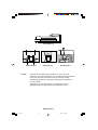
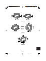
Remove Monitor Stand for Mounting
To prepare the monitor for alternate mounting purposes:
1. Disconnect all cables.
2. Place hands on each side of the monitor and lift up to the
highest position (Figure RL.1).
3. Place monitor face down on a non-abrasive surface (Place the
screen on a 50 mm platform so that the stand is parallel with the
surface.) (Figure S.1).
4. Press the “
” portion with your index finger and at the
same time slide the lower stand cover. (Figure S.2)
Next, lift up the stand, remove the lower stand cover, then go on to
remove the upper stand cover. (Figure S.3)
Return the stand to its original position, remove the 4 screws that
connect the monitor to the stand, and lift off the stand assembly.
(Figure S.4)
01b_English 28/8/01, 2:37 pm6

English-7
English
Figure RL.1
Figure R.1
Figure TS.1
5. Reverse this process to reattach stand.
NOTE: Use only VESA-compatible alternative mounting method.
01b_English 28/8/01, 2:37 pm7

English-8
Caution: Please use the attached screws (4pcs) when mounting.
To fulfil the safety requirements the monitor must be
mounted to an arm which guaranties the necessary
stability under consideration of the weight of the monitor.
The LCD monitor shall only be used with an approved arm
(e.g. GS mark).
1
2
4
3
Figure S.1
Figure S.2 Figure S.3
Figure S.4
01b_English 28/8/01, 2:37 pm8

English-9
English
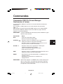
Menu
Exits the OSM controls.
Exits to the OSM main menu.
Moves the highlighted area left/right to select control
menus.
Moves the highlighted area up/down to select one of the
controls.
Moves the bar left/right to increase or decrease the
adjustment.
Activates Auto Adjust function.
Enter the sub menu.
Moves the highlighted area of main menu right to select
one of the controls.
Resets the highlighted control menu to the factory setting.
Resets the highlighted control to the factory setting.
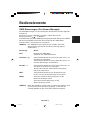
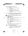
Controls
OSM (On-Screen-Manager) Controls
The OSM controls on the front of the monitor function as follows:
To access OSM press any of the control buttons ( , , -, +).
To change DVI/D-SUB signal input, press the NEXT button.
To rotate OSM between Landscape and Portrait modes, press the
RESET button.
NOTE: OSM menu must be closed in order to change signal input and
to rotate.
NOTE: When RESET is pressed in the main and sub-menu, a warning
window will appear allowing you to cancel the RESET function
by pressing the EXIT button.
Control
EXIT
CONTROL /
ADJUST -/+
NEXT
RESET
01b_English 28/8/01, 2:37 pm9

English-10
Brightness/Contrast Controls
BRIGHTNESS
Adjusts the overall image and background screen
brightness.
CONTRAST
Adjusts the image brightness in relation to the
background.
AUTO ADJUST (Analog input only)
Adjusts the image displayed for non-standard
video inputs.
Auto Adjust (Analog input only)
Automatically adjusts the Image Position, the H. Size
and Fine setting.
Position Controls (Analog input only)
LEFT/RIGHT
Controls Horizontal Image Position within the display
area of the LCD.
DOWN/UP
Controls Vertical Image Position within the display area
of the LCD.
H. SIZE
Adjusts the horizontal size by increasing or decreasing
this setting.
FINE
Improves focus, clarity and image stability by increasing
or decreasing this setting.
Colour Control Systems
Six colour presets select the desired colour setting
(sRGB and NATIVE colour presets are standard and
cannot be changed). Colour temperature increases or
decreases in each preset.
01b_English 28/8/01, 2:37 pm10

English-11
English
R,Y,G,C,B,M,S
Increases or decreases Red, Yellow, Green, Cyan, Blue,
Magenta and Saturation depending upon which is
selected. The change in colour will appear on screen
and the direction (increase or decrease) will be shown
by the colour bars.
sRGB
sRGB mode dramatically improves the colour fidelity in
the desktop environment by a single standard RGB
colour space. With this colour supported environment,
the operator could easily and confidently communicate
colours without further colour management overhead in
the most common situations.
NATIVE
Original colour presented by the LCD panel that is
unadjustable.
Tools 1
SHARPNESS
This function is digitally capable to keep crisp image at
any timings. It is continuously adjustable to get distinct
image or soft one as you prefer, and set independently
by different timings.
EXPANSION MODE
Sets the zoom method.
H-EXPANSION
The horizontal image is expanded to approximately
2 times.
V-EXPANSION
The vertical image is changeable.
VIDEO DETECT
Selects the method of video detection when more than
one computer is connected.
01b_English 28/8/01, 2:37 pm11

English-12
FIRST DETECT
The video input has to be switched to “FIRST
DETECT” mode. When current video input signal is
not present, then the monitor searches for a video
signal from the other video input port. If the video
signal is present in the other port, then the monitor
switches the video source input port to the new found
video source automatically. The monitor will not look
for other video signals while the current video source
is present.
LAST DETECT
The video input has to be switched to the “LAST
DETECT” mode. When the monitor is displaying a
signal from the current source and a new secondary
source is supplied to the monitor, then the monitor will
automatically switch to the new video source. When
current video input signal is not present, then the
monitor searches for a video signal from the other
video input port. If the video signal is present in the
other port, then the monitor switches the video source
input port to the new found video source
automatically.
NONE
The Monitor will not search the other video input port
unless the monitor is turned on.
DVI SELECTION
This function selects EDID Data for ANALOG signal or
DIGITAL signal on the DVI input.
When the DVI-D is connected to DVI, DVI Selection is
recommended to be selected to DIGITAL.
When the DVI-A is connected to DVI, DVI Selection is
recommended to be selected to ANALOG.
DIGITAL
EDID DATA for DVI DIGITAL input is available.
ANALOG
EDID DATA for DVI ANALOG input is available.
01b_English 28/8/01, 2:37 pm12
La pagina si sta caricando...
La pagina si sta caricando...
La pagina si sta caricando...
La pagina si sta caricando...
La pagina si sta caricando...
La pagina si sta caricando...
La pagina si sta caricando...
La pagina si sta caricando...
La pagina si sta caricando...
La pagina si sta caricando...
La pagina si sta caricando...
La pagina si sta caricando...
La pagina si sta caricando...
La pagina si sta caricando...
La pagina si sta caricando...
La pagina si sta caricando...
La pagina si sta caricando...
La pagina si sta caricando...
La pagina si sta caricando...
La pagina si sta caricando...
La pagina si sta caricando...
La pagina si sta caricando...
La pagina si sta caricando...
La pagina si sta caricando...
La pagina si sta caricando...
La pagina si sta caricando...
La pagina si sta caricando...
La pagina si sta caricando...
La pagina si sta caricando...
La pagina si sta caricando...
La pagina si sta caricando...
La pagina si sta caricando...
La pagina si sta caricando...
La pagina si sta caricando...
La pagina si sta caricando...
La pagina si sta caricando...
La pagina si sta caricando...
La pagina si sta caricando...
La pagina si sta caricando...
La pagina si sta caricando...
La pagina si sta caricando...
La pagina si sta caricando...
La pagina si sta caricando...
La pagina si sta caricando...
La pagina si sta caricando...
La pagina si sta caricando...
La pagina si sta caricando...
La pagina si sta caricando...
La pagina si sta caricando...
La pagina si sta caricando...
La pagina si sta caricando...
La pagina si sta caricando...
La pagina si sta caricando...
La pagina si sta caricando...
La pagina si sta caricando...
La pagina si sta caricando...
La pagina si sta caricando...
La pagina si sta caricando...
La pagina si sta caricando...
La pagina si sta caricando...
La pagina si sta caricando...
La pagina si sta caricando...
La pagina si sta caricando...
La pagina si sta caricando...
La pagina si sta caricando...
La pagina si sta caricando...
La pagina si sta caricando...
La pagina si sta caricando...
La pagina si sta caricando...
La pagina si sta caricando...
La pagina si sta caricando...
La pagina si sta caricando...
La pagina si sta caricando...
La pagina si sta caricando...
La pagina si sta caricando...
La pagina si sta caricando...
La pagina si sta caricando...
La pagina si sta caricando...
La pagina si sta caricando...
La pagina si sta caricando...
La pagina si sta caricando...
La pagina si sta caricando...
La pagina si sta caricando...
La pagina si sta caricando...
La pagina si sta caricando...
La pagina si sta caricando...
La pagina si sta caricando...
La pagina si sta caricando...
La pagina si sta caricando...
La pagina si sta caricando...
La pagina si sta caricando...
La pagina si sta caricando...
La pagina si sta caricando...
La pagina si sta caricando...
La pagina si sta caricando...
La pagina si sta caricando...
La pagina si sta caricando...
La pagina si sta caricando...
La pagina si sta caricando...
La pagina si sta caricando...
La pagina si sta caricando...
La pagina si sta caricando...
La pagina si sta caricando...
La pagina si sta caricando...
La pagina si sta caricando...
La pagina si sta caricando...
La pagina si sta caricando...
La pagina si sta caricando...
La pagina si sta caricando...
La pagina si sta caricando...
La pagina si sta caricando...
La pagina si sta caricando...
La pagina si sta caricando...
La pagina si sta caricando...
La pagina si sta caricando...
La pagina si sta caricando...
La pagina si sta caricando...
La pagina si sta caricando...
La pagina si sta caricando...
La pagina si sta caricando...
La pagina si sta caricando...
La pagina si sta caricando...
La pagina si sta caricando...
La pagina si sta caricando...
La pagina si sta caricando...
La pagina si sta caricando...
La pagina si sta caricando...
La pagina si sta caricando...
La pagina si sta caricando...
La pagina si sta caricando...
La pagina si sta caricando...
La pagina si sta caricando...
La pagina si sta caricando...
La pagina si sta caricando...
La pagina si sta caricando...
La pagina si sta caricando...
La pagina si sta caricando...
La pagina si sta caricando...
La pagina si sta caricando...
La pagina si sta caricando...
La pagina si sta caricando...
La pagina si sta caricando...
La pagina si sta caricando...
La pagina si sta caricando...
La pagina si sta caricando...
La pagina si sta caricando...
La pagina si sta caricando...
La pagina si sta caricando...
La pagina si sta caricando...
La pagina si sta caricando...
La pagina si sta caricando...
La pagina si sta caricando...
La pagina si sta caricando...
La pagina si sta caricando...
La pagina si sta caricando...
La pagina si sta caricando...
La pagina si sta caricando...
La pagina si sta caricando...
La pagina si sta caricando...
La pagina si sta caricando...
La pagina si sta caricando...
La pagina si sta caricando...
La pagina si sta caricando...
La pagina si sta caricando...
La pagina si sta caricando...
La pagina si sta caricando...
La pagina si sta caricando...
La pagina si sta caricando...
La pagina si sta caricando...
La pagina si sta caricando...
La pagina si sta caricando...
La pagina si sta caricando...
La pagina si sta caricando...
La pagina si sta caricando...
La pagina si sta caricando...
La pagina si sta caricando...
La pagina si sta caricando...
La pagina si sta caricando...
La pagina si sta caricando...
La pagina si sta caricando...
La pagina si sta caricando...
La pagina si sta caricando...
La pagina si sta caricando...
La pagina si sta caricando...
La pagina si sta caricando...
La pagina si sta caricando...
La pagina si sta caricando...
La pagina si sta caricando...
-
 1
1
-
 2
2
-
 3
3
-
 4
4
-
 5
5
-
 6
6
-
 7
7
-
 8
8
-
 9
9
-
 10
10
-
 11
11
-
 12
12
-
 13
13
-
 14
14
-
 15
15
-
 16
16
-
 17
17
-
 18
18
-
 19
19
-
 20
20
-
 21
21
-
 22
22
-
 23
23
-
 24
24
-
 25
25
-
 26
26
-
 27
27
-
 28
28
-
 29
29
-
 30
30
-
 31
31
-
 32
32
-
 33
33
-
 34
34
-
 35
35
-
 36
36
-
 37
37
-
 38
38
-
 39
39
-
 40
40
-
 41
41
-
 42
42
-
 43
43
-
 44
44
-
 45
45
-
 46
46
-
 47
47
-
 48
48
-
 49
49
-
 50
50
-
 51
51
-
 52
52
-
 53
53
-
 54
54
-
 55
55
-
 56
56
-
 57
57
-
 58
58
-
 59
59
-
 60
60
-
 61
61
-
 62
62
-
 63
63
-
 64
64
-
 65
65
-
 66
66
-
 67
67
-
 68
68
-
 69
69
-
 70
70
-
 71
71
-
 72
72
-
 73
73
-
 74
74
-
 75
75
-
 76
76
-
 77
77
-
 78
78
-
 79
79
-
 80
80
-
 81
81
-
 82
82
-
 83
83
-
 84
84
-
 85
85
-
 86
86
-
 87
87
-
 88
88
-
 89
89
-
 90
90
-
 91
91
-
 92
92
-
 93
93
-
 94
94
-
 95
95
-
 96
96
-
 97
97
-
 98
98
-
 99
99
-
 100
100
-
 101
101
-
 102
102
-
 103
103
-
 104
104
-
 105
105
-
 106
106
-
 107
107
-
 108
108
-
 109
109
-
 110
110
-
 111
111
-
 112
112
-
 113
113
-
 114
114
-
 115
115
-
 116
116
-
 117
117
-
 118
118
-
 119
119
-
 120
120
-
 121
121
-
 122
122
-
 123
123
-
 124
124
-
 125
125
-
 126
126
-
 127
127
-
 128
128
-
 129
129
-
 130
130
-
 131
131
-
 132
132
-
 133
133
-
 134
134
-
 135
135
-
 136
136
-
 137
137
-
 138
138
-
 139
139
-
 140
140
-
 141
141
-
 142
142
-
 143
143
-
 144
144
-
 145
145
-
 146
146
-
 147
147
-
 148
148
-
 149
149
-
 150
150
-
 151
151
-
 152
152
-
 153
153
-
 154
154
-
 155
155
-
 156
156
-
 157
157
-
 158
158
-
 159
159
-
 160
160
-
 161
161
-
 162
162
-
 163
163
-
 164
164
-
 165
165
-
 166
166
-
 167
167
-
 168
168
-
 169
169
-
 170
170
-
 171
171
-
 172
172
-
 173
173
-
 174
174
-
 175
175
-
 176
176
-
 177
177
-
 178
178
-
 179
179
-
 180
180
-
 181
181
-
 182
182
-
 183
183
-
 184
184
-
 185
185
-
 186
186
-
 187
187
-
 188
188
-
 189
189
-
 190
190
-
 191
191
-
 192
192
-
 193
193
-
 194
194
-
 195
195
-
 196
196
-
 197
197
-
 198
198
-
 199
199
-
 200
200
-
 201
201
-
 202
202
-
 203
203
-
 204
204
-
 205
205
-
 206
206
-
 207
207
-
 208
208


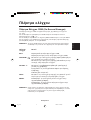
NEC MultiSync® LCD1550X Manuale del proprietario
- Categoria
- TV
- Tipo
- Manuale del proprietario
- Questo manuale è adatto anche per
in altre lingue
Documenti correlati
-
NEC MultiSync® LCD1550V Manuale del proprietario
-
-
NEC MultiSync® LCD1850E Manuale del proprietario
-
NEC MultiSync® LCD1980SX Manuale del proprietario
-
-
NEC MultiSync LCD1525X Serie Manuale del proprietario
-
-
-
-