
CYCLADES
®
PM IPDU
Installer/User Guide

FCC Warning Statement
The Cyclades PM IPDU has been tested and found to comply with the limits for Class A digital devices,
pursuant to Part 15 of the FCC rules. These limits are designed to provide reasonable protection against harmful
interference when the equipment is operated in a commercial environment. This equipment generates, uses, and
can radiate radio frequency energy and, if not installed and used in accordance with the Installation & Service
Manual, may cause harmful interference to radio communications. Operation of this equipment in a residential
area is likely to cause harmful interference in which case the user is required to correct the problem at his or her
own expense.
Canadian DOC Notice
The Cyclades PM IPDU does not exceed the Class A limits for radio noise emissions from digital apparatus set
out in the Radio Interference Regulations of the Canadian Department of Communications.
Le Cyclades PM n’émete pas de bruits radioélectriques dépassant les limites applicables aux appareils numéri-
ques de la classe A prescrites dans le règlement sur le brouillage radioélectrique edicté par le Ministère des
Communications du Canada.
Japanese Approvals
Safety and EMC Approvals and Markings
FCC, ICES-003, CE, C-tick, VCCI, CB, PSE, GOSTR
Safety certifications and EMC certifications for this product are obtained under one or more of the following
designations: CMN (Certification Model Number), MPN (Manufacturer’s Part Number) or Sales Level Model
designation. The designation that is referenced in the EMC and/or safety reports and certificates are printed on
the label applied to this product.

Cyclades
®
PM IPDU
Installer/Administrator/User Guide
Avocent, the Avocent logo, The Power of Being There, Cyclades and
DSR are registered trademarks of Avocent Corporation or its affiliates in
the U.S. and other countries. All other marks are the property of their
respective owners.
© 2009 Avocent Corporation. 590-667-501D
pm_install_admin_user.book Page i Tuesday, March 24, 2009 3:02 PM

Instructions
This symbol is intended to alert the user to the presence of important operating and maintenance
(servicing) instructions in the literature accompanying the appliance.
Dangerous Voltage
This symbol is intended to alert the user to the presence of uninsulated dangerous voltage within the
product’s enclosure that may be of sufficient magnitude to constitute a risk of electric shock to persons.
Power On
This symbol indicates the principal on/off switch is in the on position.
Power Off
This symbol indicates the principal on/off switch is in the off position.
Protective Grounding Terminal
This symbol indicates a terminal which must be connected to earth ground prior to making any other
connections to the equipment.
pm_install_admin_user.book Page ii Tuesday, March 24, 2009 3:02 PM

iii
Table of Contents
List of Figures ................................................................................................................ vii
List of Tables................................................................................................................... ix
Chapter 1: Introduction ................................................................................................... 1
Features and Benefits ........................................................................................................................1
Alarms and monitoring...............................................................................................................1
Sequential power application.....................................................................................................1
Support for daisy chaining .........................................................................................................1
Integration with Avocent management products........................................................................2
Hardware Configuration Options......................................................................................................2
Standalone configuration ...........................................................................................................2
Daisy chained configuration.......................................................................................................3
Integrated configuration.............................................................................................................3
Chapter 2: Installation ..................................................................................................... 5
Getting Started...................................................................................................................................5
Supplied with the PM IPDU ..............................................................................................................5
Modular input power cables for the PM IPDU..........................................................................5
Optional outlet cable package....................................................................................................6
Rack Mounting the PM IPDU............................................................................................................6
Installation environment.............................................................................................................7
Daisy Chaining PM IPDUs ...............................................................................................................9
Accessing the Console .......................................................................................................................9
Direct console access .................................................................................................................9
Console access through a management device ........................................................................10
Configuring the PM IPDU...............................................................................................................10
Default configuration parameters ............................................................................................10
Initial configuration using the command prompt.....................................................................10
Resetting the admin password..................................................................................................11
Upgrading the PM IPDU firmware..........................................................................................12
Chapter 3: Accessing the PM IPDU via the Command Line Interface....................... 13
PM IPDU User Interface.................................................................................................................13
TABLE OF CONTENTS
pm_install_admin_user.book Page iii Tuesday, March 24, 2009 3:02 PM

iv Cyclades PM IPDU Installer/Administrator/User Guide
Daisy chained PM IPDUs in the login prompt.........................................................................13
Logging in to the PM IPDU......................................................................................................13
Commands .......................................................................................................................................14
adduser.............................................................................................................................................14
alarm................................................................................................................................................14
assign ...............................................................................................................................................15
buzzer...............................................................................................................................................16
current..............................................................................................................................................16
currentprotection .............................................................................................................................17
cycle .................................................................................................................................................18
dbsync ..............................................................................................................................................19
deluser..............................................................................................................................................19
display..............................................................................................................................................19
exit....................................................................................................................................................21
factory_default.................................................................................................................................21
help...................................................................................................................................................21
humidity ...........................................................................................................................................22
hwocp...............................................................................................................................................23
id ......................................................................................................................................................23
interval.............................................................................................................................................24
list.....................................................................................................................................................25
lock...................................................................................................................................................25
name.................................................................................................................................................26
off .....................................................................................................................................................26
on .....................................................................................................................................................27
outcycledelay ...................................................................................................................................27
passwd..............................................................................................................................................28
reboot...............................................................................................................................................28
restore..............................................................................................................................................29
save ..................................................................................................................................................29
status................................................................................................................................................29
syslog ...............................................................................................................................................30
temperature......................................................................................................................................31
unassign ...........................................................................................................................................31
unlock...............................................................................................................................................32
pm_install_admin_user.book Page iv Tuesday, March 24, 2009 3:02 PM

Table of Contents v
upgrade............................................................................................................................................32
ver ....................................................................................................................................................33
voltage..............................................................................................................................................34
whoami.............................................................................................................................................34
Appendices..................................................................................................................... 35
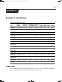
Appendix A: Specifications..............................................................................................................35
Appendix B: Safety Instructions.......................................................................................................38
Appendix C: Circuit Breakers..........................................................................................................42
Appendix D: Technical Support.......................................................................................................48
pm_install_admin_user.book Page v Tuesday, March 24, 2009 3:02 PM

vi Cyclades PM IPDU Installer/Administrator/User Guide
pm_install_admin_user.book Page vi Tuesday, March 24, 2009 3:02 PM

vii
List of Figures
Figure 1.1: Standalone Configuration...............................................................................................2
Figure 1.2: Daisy Chained PM IPDUs with an Avocent Management Device.................................3
Figure 2.1: Rack Mount Bracket Installation on a PM IPDU...........................................................6
Figure 2.2: A Sample PM IPDU (PM42 Shown)...............................................................................8
Figure C.1: PM10-L30A IPDU Circuit Breakers ..........................................................................43
Figure C.2: PM10i-L30A IPDU Circuit Breakers .........................................................................44
Figure C.3: PM20-L30A IPDU Circuit Breakers ..........................................................................45
Figure C.4: PM20i-L30A IPDU, PM20i-32A IPDU and PM20i-32Au IPDU Circuit Breakers ...46
LIST OF FIGURES
pm_install_admin_user.book Page vii Tuesday, March 24, 2009 3:02 PM

viii Cyclades PM IPDU Installer/Administrator/User Guide
pm_install_admin_user.book Page viii Tuesday, March 24, 2009 3:02 PM

ix
List of Tables
Table 1.1: Standalone Configuration Descriptions...........................................................................2
Table 2.1: PM IPDU Shipping Box Contents and Description.........................................................5
Table 2.2: PM IPDU Optimum Installation Environment.................................................................7
Table 2.3: Cyclades PM42 IPDU Callout Descriptions....................................................................8
Table A.1: PM IPDU Specifications................................................................................................35
Table A.2: PM42 IPDU Specifications............................................................................................36
Table A.3: Pinouts for IN and OUT RS-232 Serial Ports................................................................36
Table C.5: Circuit Breaker Trip Time .............................................................................................47
Table C.6: PM42 IPDU Shutdown Time .........................................................................................47
LIST OF TABLES
pm_install_admin_user.book Page ix Tuesday, March 24, 2009 3:02 PM

x Cyclades PM IPDU Installer/Administrator/User Guide
pm_install_admin_user.book Page x Tuesday, March 24, 2009 3:02 PM

1
Introduction
This installation, administration and user’s guide provides background information and procedures
for installing, configuring and maintaining the Cyclades
®
Power Management (PM) Intelligent
Power Distribution Unit (IPDU) family.
The Cyclades PM IPDU enables remote power control of servers and network gear. When used in
conjunction with DSR
®
switches or console servers, the PM IPDU delivers easier management
capabilities and faster problem solving by integrating console/KVM access and power control into
one single interface.
The following sections describe general features common to all PM IPDU models and point out
specific features of certain units.
Features and Benefits
Alarms and monitoring
The PM IPDU delivers accurate, real-time global current monitoring of all connected devices via
the user interface screen or locally through an LED digital display. Users have the ability to set a
current alarm threshold that, once exceeded, will cause the PM IPDU to sound an alarm or send a
notification message, or both.
Sequential power application
The PM IPDU incorporates a sequential power application feature that prevents all power outlet
receptacles from turning on at once, eliminating the potential of current surges that could render the
equipment inoperable. Together with the global current monitoring, the sequential power
application feature lets users safely install more equipment on existing power circuits without the
worry of current overloads.
Support for daisy chaining
The IPDU has a fixed number of power outlet receptacles, but with daisy chaining capabilities,
users may increase capacity by connecting the control interfaces of several PM IPDUs in a series.
CHAPTER
1
pm_install_admin_user.book Page 1 Tuesday, March 24, 2009 3:02 PM

2 Cyclades PM IPDU Installer/Administrator/User Guide
Integration with Avocent management products
The PM IPDU can be combined with an ACS console server or DSR KVM switch to provide
enhanced functionality. Please refer to the appropriate product documentation for more information
on how to use the PM IPDU with your specific implementation.
Hardware Configuration Options
The PM IPDU may be used in one of three hardware configurations:
• Standalone – Managed independently of any other hardware device.
• Daisy chained - Multiple PM IPDUs connected to one another and managed by one main
PM IPDU.
• Integrated – Managed by a console server or a KVM switch.
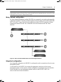
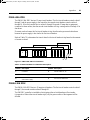
Standalone configuration
In a standalone configuration, the PM IPDU operates independently of any other hardware. The
following graphic displays a PM IPDU with the console port connected to a computer running
terminal emulation.
Figure 1.1: Standalone Configuration
Table 1.1: Standalone Configuration Descriptions
Number Description Number Description
1 RJ-45 to DB-9F Adaptor (Optional) 4 Server
2 RJ-45 Cable 5 Switch
3 IN Port 6 Power Source
1
2
3
4
5
6
pm_install_admin_user.book Page 2 Tuesday, March 24, 2009 3:02 PM

Chapter 1: Introduction 3
NOTE: The installation example displays the PM IPDU being connected with the RJ-45 to DB-9F adaptor that is
shipped with the product. If the unit you are connected to does not have a DB-9M COM port, you may use a USB
serial adaptor and connect to a USB port when possible.
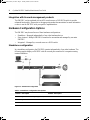
Daisy chained configuration
In a daisy chained configuration, multiple PM IPDUs are connected to one another and managed by
a single main PM IPDU. The PMs are linked together with RJ-45 cables connected through the PM
IPDU’s IN and OUT ports. The following example shows three PM IPDUs operating in a daisy
chained environment. PM IPDU #1 is connected to the local workstation and is the “main”
PM IPDU.
Figure 1.2: Daisy Chained PM IPDUs with an Avocent Management Device
Integrated configuration
In an integrated configuration, the PM IPDU is configured to work in conjunction with an Avocent
management product.
A user connects to the PM IPDU by accessing the appropriate console port of the Avocent
management product. In this scenario, software configuration on and monitoring of the PM IPDU
is done through the Avocent management product and not on the PM IPDU itself. Visit
www.avocent.com for more information.
pm_install_admin_user.book Page 3 Tuesday, March 24, 2009 3:02 PM

4 Cyclades PM IPDU Installer/Administrator/User Guide
pm_install_admin_user.book Page 4 Tuesday, March 24, 2009 3:02 PM

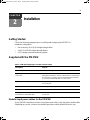
5
Installation
Getting Started
Collect the following equipment prior to installing and configuring the PM IPDU in
standalone configuration:
• One or more RJ-45 to RJ-45 straight-through cables
• An RJ-45 to DB-9F straight-through adaptor
• A PC running a terminal emulation program
Supplied with the PM IPDU
Modular input power cables for the PM IPDU
If your PM IPDU model does not have a fixed power input cable, it may ship with a modular cable.
Depending on your site’s location, the modular input power cables included in the box vary.
Table 2.1: PM IPDU Shipping Box Contents and Description
Description Purpose
PM IPDU Quick Installation Guide (QIG) Basic installation guide in printed format.
RJ-45 to RJ-45 7ft. straight through
CAT5 cable
Used for the following:
Along with an adaptor, to connect a terminal or PC to the IN port.
To connect to a Cyclades console or KVM management device.
To connect to another PM IPDU in a daisy chain.
RJ-45 to DB-9F straight-through adaptor Along with an RJ-45 cable, used to connect a terminal or PC to a
PC’s COM port.
RJ-45 loopback connector Used to gain temporary access to the PM IPDU.
PM IPDU to DSR switch cable adaptor Used to connect a PM IPDU to an Avocent switch’s SPC port.
Mounting brackets and screws (2 spares)
for PM10 IPDU and PM10i IPDU
Use to mount the Cyclades PM10 IPDU and PM10i IPDU to a
rack or wall.
CHAPTER
2
pm_install_admin_user.book Page 5 Tuesday, March 24, 2009 3:02 PM

6 Cyclades PM IPDU Installer/Administrator/User Guide
NOTE: The Cyclades PM 10i-32Au IPDU ships with an unterminated power cord. If necessary, contact Avocent
Technical Support for guidelines on approved power plug installation.
Optional outlet cable package
The following cable packages may be ordered separately for the IEC PM IPDU models:
• 8-outlet cables (C13 female to C14 male)
• 10-outlet cables (C13 female to C14 male)
Rack Mounting the PM IPDU
You may mount the PM IPDU on a rack or wall or place it on a desktop or other flat surface. Two
brackets are supplied with six Phillips screws for attaching the brackets to the PM8i IPDU, the
PM10 IPDU and the PM10i IPDU for mounting.
If you are mounting the PM IPDU, obtain a Phillips screwdriver and appropriate nuts and bolts
before mounting the PM IPDU.
NOTE: When mounting a PM IPDU zero U model to a wall stud, securely mount it by using a #10 (4.8 mm or
0.19 in or 3/16 in) or larger screw or use a drywall fastener rated min. 25 lb. (11.34 kg).
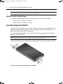
The following graphic depicts the orientation of the brackets for front rack mounting a PM IPDU.
Figure 2.1: Rack Mount Bracket Installation on a PM IPDU
pm_install_admin_user.book Page 6 Tuesday, March 24, 2009 3:02 PM

Chapter 2: Installation 7
Installation environment
When installing the PM IPDU, ensure that the following environment specifications are met.
NOTE: Install a PM IPDU 0U model in a location where there is an adjacent and accessible socket outlet.
CAUTION: The plug on the power cord of the PM IPDU is used as the disconnect device.
To mount the PM10 IPDU or PM10i IPDU:
1. Using a Phillips screwdriver, attach the supplied brackets to the sides of the PM IPDU.
2. Use the mounting hardware recommended for your rack to mount the PM IPDU.
Table 2.2: PM IPDU Optimum Installation Environment
Environment Factor Recommendation
Temperature The manufacturer's maximum recommended ambient temperature for the
PM IPDU is 122 ºF (50 ºC).
Elevated Operating Ambient
Temperature
If the PM IPDU is installed in a closed or multi-unit rack assembly, the
operating ambient temperature of the rack environment may be greater
than room ambient temperature. Therefore, consideration should be given
to installing the equipment in an environment compatible with the
manufacturer’s maximum rated ambient temperature. See above.
Reduced Air Flow Installation of the equipment in a rack should be such that the amount of air
flow required for safe operation of the equipment is not compromised.
Mechanical Loading Mounting of the equipment in the rack should be such that a hazardous
condition is not created due to uneven mechanical loading.
Circuit Overloading Consideration should be given to the connection of the equipment to the
supply circuit and the effect that overloading of circuits might have on
overcurrent protection and supply wiring. Appropriate consideration of
equipment nameplate ratings should be used when addressing
this concern.
Reliable Grounding Reliable grounding of rack-mounted equipment should be maintained.
Particular attention should be given to supply connections other than direct
connections to the branch circuit, such as power strips or extension cords.
pm_install_admin_user.book Page 7 Tuesday, March 24, 2009 3:02 PM

8 Cyclades PM IPDU Installer/Administrator/User Guide
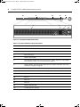
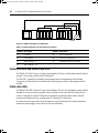
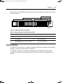
Figure 2.2: A Sample PM IPDU (PM42 Shown)
Table 2.3: Cyclades PM42 IPDU Callout Descriptions
Number/Letter Description
1 Outlet, IEC320-C13, 14 each for bank XY, YZ and XZ
2 RS-232 (IN) Port
3 MULTI (OUT) Port
4 HWOCP Reset Button
5 Three digit LED displays the current on Phase X, Y and Z in sequence, or the voltage
across Phases X and Y, Y and Z, and X and Z in sequence
6 SCROLL button - manually toggles display when the display command is set to cycle
manually (see display on page 19)
7 LED indicates when Phase X current is displayed
8 LED indicates when Phase Y current is displayed
9 LED indicates when Phase Z current is displayed
10 Bank XY
11 Bank YZ
12 Bank XZ
13 HWOCP Indicator LED
14 L21-30P 208 VAC 30A Plug
4
1
2
3
5
7
8
9
6
10
11
12
13
14
pm_install_admin_user.book Page 8 Tuesday, March 24, 2009 3:02 PM
La pagina sta caricando ...
La pagina sta caricando ...
La pagina sta caricando ...
La pagina sta caricando ...
La pagina sta caricando ...
La pagina sta caricando ...
La pagina sta caricando ...
La pagina sta caricando ...
La pagina sta caricando ...
La pagina sta caricando ...
La pagina sta caricando ...
La pagina sta caricando ...
La pagina sta caricando ...
La pagina sta caricando ...
La pagina sta caricando ...
La pagina sta caricando ...
La pagina sta caricando ...
La pagina sta caricando ...
La pagina sta caricando ...
La pagina sta caricando ...
La pagina sta caricando ...
La pagina sta caricando ...
La pagina sta caricando ...
La pagina sta caricando ...
La pagina sta caricando ...
La pagina sta caricando ...
La pagina sta caricando ...
La pagina sta caricando ...
La pagina sta caricando ...
La pagina sta caricando ...
La pagina sta caricando ...
La pagina sta caricando ...
La pagina sta caricando ...
La pagina sta caricando ...
La pagina sta caricando ...
La pagina sta caricando ...
La pagina sta caricando ...
La pagina sta caricando ...
La pagina sta caricando ...
La pagina sta caricando ...
La pagina sta caricando ...
La pagina sta caricando ...
-
 1
1
-
 2
2
-
 3
3
-
 4
4
-
 5
5
-
 6
6
-
 7
7
-
 8
8
-
 9
9
-
 10
10
-
 11
11
-
 12
12
-
 13
13
-
 14
14
-
 15
15
-
 16
16
-
 17
17
-
 18
18
-
 19
19
-
 20
20
-
 21
21
-
 22
22
-
 23
23
-
 24
24
-
 25
25
-
 26
26
-
 27
27
-
 28
28
-
 29
29
-
 30
30
-
 31
31
-
 32
32
-
 33
33
-
 34
34
-
 35
35
-
 36
36
-
 37
37
-
 38
38
-
 39
39
-
 40
40
-
 41
41
-
 42
42
-
 43
43
-
 44
44
-
 45
45
-
 46
46
-
 47
47
-
 48
48
-
 49
49
-
 50
50
-
 51
51
-
 52
52
-
 53
53
-
 54
54
-
 55
55
-
 56
56
-
 57
57
-
 58
58
-
 59
59
-
 60
60
-
 61
61
-
 62
62


Avocent Cyclades PM20i-16A Installer/User Manual
- Tipo
- Installer/User Manual
in altre lingue
- English: Avocent Cyclades PM20i-16A
Documenti correlati
Altri documenti
-
Pentax MMK-AP0121H Manuale utente
-
Toshiba MMU-AP0071YH Manuale utente
-
Toshiba MMD-AP0071SPH Manuale del proprietario
-
 Olimpia Splendid SHERPA 4 Guida d'installazione
-
 Olimpia Splendid Sherpa AQUADUE TOWER S2 Manuale d'installazione
-
Chariot Carriers Merci Guida d'installazione
-
Carrier 40SMC024N Guida d'installazione
-
Belkin OMNIVIEW SMB CAT5 KVM SWITCH Manuale del proprietario

