3com AP9552 Hardware Installation Manual
- Tipo
- Hardware Installation Manual

3Com AP9552 Dual Band 802.11n PoE
Access Point
Hardware Installation Guide
BOM: 3122A08T
3C Number:
3CRWE955275(FAT Mode)
3CRWE9552A75(FIT Mode)
Manual Version: 6PW104
www.3com.com
3Com Corporation
350 Campus Drive, Marlborough, MA, USA
01752 3064
English...1
Français...14
Italiano...28
Polski...42
Português Brazilian...56
Deutsch...69
Español Latino...82
Espanol...97
Regulatory Information...112
List of the Hazardous Substances...119

Copyright © 2009-2010, 3Com Corporation. All rights reserved. No part of this
documentation may be reproduced in any form or by any means or used to make any
derivative work (such as translation, transformation, or adaptation) without written
permission from 3Com Corporation.
3Com Corporation reserves the right to revise this documentation and to make
changes in content from time to time without obligation on the part of 3Com Corporation
to provide notification of such revision or change.
3Com Corporation provides this documentation without warranty, term, or condition of
any kind, either implied or expressed, including, but not limited to, the implied
warranties, terms or conditions of merchantability, satisfactory quality, and fitness for a
particular purpose. 3Com may make improvements or changes in the product(s) and/or
the program(s) described in this documentation at any time.
If there is any software on removable media described in this documentation, it is
furnished under a license agreement included with the product as a separate document,
in the hard copy documentation, or on the removable media in a directory file named
LICENSE.TXT or !LICENSE.TXT. If you are unable to locate a copy, please contact
3Com and a copy will be provided to you.
UNITED STATES GOVERNMENT LEGEND
If you are a United States government agency, then this documentation and the
software described herein are provided to you subject to the following:
All technical data and computer software are commercial in nature and developed
solely at private expense. Software is delivered as “Commercial Computer Software” as
defined in DFARS 252.227-7014 (June 1995) or as a “commercial item” as defined in
FAR 2.101(a) and as such is provided with only such rights as are provided in 3Com’s
standard commercial license for the Software. Technical data is provided with limited
rights only as provided in DFAR 252.227-7015 (Nov 1995) or FAR 52.227-14 (June
1987), whichever is applicable. You agree not to remove or deface any portion of any
legend provided on any licensed program or documentation contained in, or delivered
to you in conjunction with, this User Guide.
Unless otherwise indicated, 3Com registered trademarks are registered in the United
States and may or may not be registered in other countries.
3Com and the 3Com logo are registered trademarks of 3Com Corporation.
All other company and product names may be trademarks of the respective companies
with which they are associated.
ENVIRONMENTAL STATEMENT
It is the policy of 3Com Corporation to be environmentally-friendly in all operations. To
uphold our policy, we are committed to:
Establishing environmental performance standards that comply with national legislation
and regulations.
Conserving energy, materials and natural resources in all operations.
Reducing the waste generated by all operations. Ensuring that all waste conforms to
recognized environmental standards. Maximizing the recyclable and reusable content
of all products.
Ensuring that all products can be recycled, reused and disposed of safely.

Ensuring that all products are labelled according to recognized environmental
standards.
Improving our environmental record on a continual basis.
End of Life Statement
3Com processes allow for the recovery, reclamation and safe disposal of all
end-of-life electronic components.
Regulated Materials Statement
3Com products do not contain any hazardous or ozone-depleting material.
Environmental Statement about the Documentation
The documentation for this product is printed on paper that comes from sustainable,
managed forests; it is fully biodegradable and recyclable, and is completely
chlorine-free. The varnish is environmentally-friendly, and the inks are
vegetable-based with a low heavy-metal content.
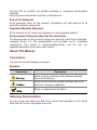
About This Manual
Conventions
The manual uses the following conventions:
Symbols
Convention Description
Means reader be extremely careful. Improper operation
may cause bodily injury.
Means reader be careful. Improper operation may cause
data loss or damage to equipment.
Means a complementary description.
Obtaining Documentation
You can access the most up-to-date 3Com product documentation on the World
Wide Web at this URL: http://www.3com.com.

1
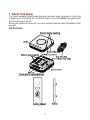
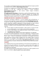
1 About This Guide
This Quick Hardware Install Guide describes the basic steps necessary to install and
configure your 3Com 9552 (11n 2.4+5GHz PoE) Access Point. Note: This guide refers
to these devices as the AP.
Before you install or move the AP, you must carefully read the safety information of this
manual.
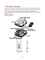
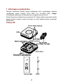
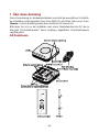
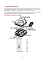
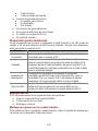
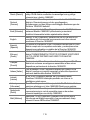
AP Features

2
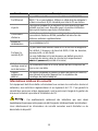
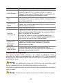
Feature Description
Ethernet Port
The Ethernet port provides a 10/100/1000 BASE-T Ethernet
connection to a switch. Use a suitable Category 5 cable with
straight-through wiring and standard RJ-45 connectors to
connect your AP to the network.
LEDs
The LEDs indicate power and activity. See
Checking the LED
Indicators for details.
Antenna Connectors
The AP has three built-in internal antennas. In addition, three
RSMA antenna connectors allow you to connect optional
external antennas.
Reset Button To reset the AP.
RJ-45 Console Port
Provides a serial interface to the AP for diagnostic use.
Default: 9600 baud rate, 8 data bits, no parity, one stop bit.
The default username and password for console login are
admin
and
password
(case sensitive) respectively.
Wall-Mounting
Bracket and
Table-Top Stand
The combined wall-mounting bracket and table-top stand
allows you to mount the unit on a wall or stand it on a table top.
Suspended Ceiling
Bracket
The suspended ceiling bracket (ceiling bracket and slider)
allows you to mount the unit on a suitably ceiling tile separator.
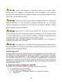
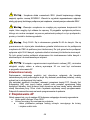
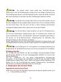
Safety Information
This equipment must be installed in compliance with local and national building codes,
regulatory restrictions, and FCC rules. For the safety of people and equipment, only
professional network personnel should install the AP.
: Warnings contain directions that you must follow for your personal
safety. Follow all directions carefully.
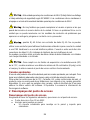
You must read the following safety information carefully before you install or remove the unit.
: Exceptional care must be taken during installation and removal of the unit.
: This unit operates under SELV (Safety Extra Low Voltage) conditions
according to IEC60950-1. The conditions are only maintained if the equipment to which
it is connected also operates under SELV conditions.

3
: There are no user-replaceable fuses or user-serviceable parts inside
the unit. If you have a physical problem with the unit that cannot be solved with problem
solving actions in this guide, contact your supplier.
: RJ-45 ports. These are RJ-45 data sockets. They cannot be used as
standard traditional telephone sockets, or to connect the unit to a traditional PBX or
public telephone network. Only connect RJ-45 data connectors, network telephony
systems, or network telephones to these sockets.
Either shielded or unshielded data cables with shielded or unshielded jacks can be
connected to these data sockets.
: To comply with FCC radio frequency (RF) exposure limits, a minimum
body-to-antenna distance of 20 cm must be maintained when the AP is operational.
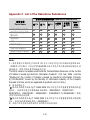
Approved Channels
Use of this product is only authorized for the channels approved by each country. For
proper installation, select your country from the country-selection list.
To conform to FCC, Canada, EU and other country restrictions, your product as
shipped may be limited in the channels that are available. If other channels are
permitted your country, please visit the 3Com web site for the latest software version.
The Appendix A lists the Software Downloads information.
2 Mounting the AP
Unpacking the AP
Make sure that you have the following items, which are included with the AP:
z One 3Com 9552 Access Point
z Wall-mounting hardware:
z One combined wall-mounting bracket and table-top stand
z Four screws
z Four wall anchors
z Suspended ceiling bracket:
z One ceiling bracket
z One slider
z Two screws

4
z Eight adhesive rubber feet
z One copy of this Quick Start Guide
z One 3Com Warranty Flyer
z One console cable
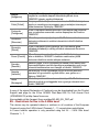
Preparing for Installation
3Com recommends that you connect and check the Ethernet cable and LEDs before
you install the AP in a hard-to-reach location. Also, observe these items before you
mount or connect the AP:
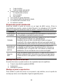
Feature Description
Switch
Port
To connect your wireless network to your wired network, you need a
switch that is connected to the AP.
Cabling
Make sure that a standard Ethernet cable with straight-through wiring is
installed at the site before you install the AP.
Make sure that the cable is highly flexible and that the RJ-45 connector
has no extra covering that could prevent the cable from being routed
through the mounting bracket.
Power
Requirem
ent
Power is supplied using an 802.3af Power Over Ethernet (PoE)
compliant device such as a PoE switch or a PoE injector. For maximum
performance, 3Com recommends that you use a Gigabit link.
MAC
Address
Record the AP MAC address in a safe place before the AP is installed in
a hard-to-reach location.
The MAC address is printed on the back of the AP.
Mounting the AP
The AP can be mounted on the following types of surfaces:
z Wall or electrical box (NEMA enclosure)
z Table top
z Ceiling mounting
Wall or Electrical Box Mounting
To install your AP on a wall or electrical box, use the mounting bracket that comes with
the device. Follow these steps:
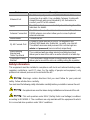
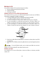
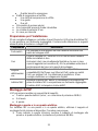
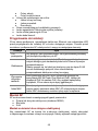
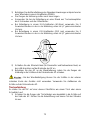
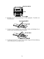
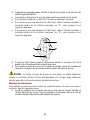
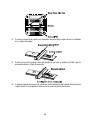
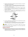
1) Following these guidelines, screw the mounting bracket to a wall or electrical
box (NEMA enclosure):
z The mounting bracket tabs should be pointing upward.
z If mounting to drywall, use the 4 screws and 4 wall anchors.

5
z If mounting to an EU electrical box (60.3mm), use 2 threaded screws and
insert into the holes marked “A” in the diagram shown below.
z If mounting to a US electrical box (83.3mm), use 2 threaded screws and insert
into the holes marked “B” in the diagram shown below.
2) Connect the Ethernet cable (for power and network connection) to the LAN
port on the back of the AP.
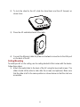
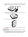
3) To mount the AP onto the mounting bracket, insert the mounting-bracket tabs
into the slots on the back of the AP.
: If you are mounting the AP on a wall, you cannot use the slots on the
bottom narrow edge of the device. Instead, you must use the slots on back of the AP.
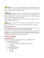
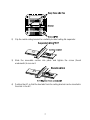
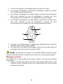
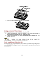
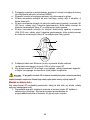
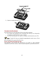
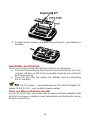
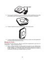
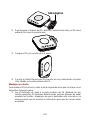
Tabletop Mounting
To install the AP on a flat surface such as a table or desktop, follow these steps:
1) Insert the tabs on the table stand into the slots on the side of the AP, as shown
in the illustration. Align the cable routing cut out toward the upper part of the
stand.

6
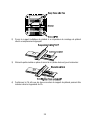
2) To lock the stand to the AP, slide the stand back and the AP forward, as
shown here:
3) Place the AP and table stand on the table.
4) Connect the Ethernet cable for power and network connection to the LAN port
on the back of the AP.
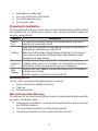
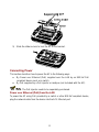
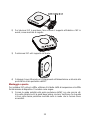
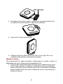
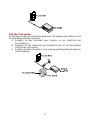
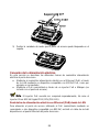
Ceiling Mounting
To install your AP on the ceiling, use the ceiling bracket kit that comes with the device.
Follow these steps:
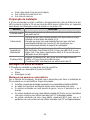
1) Attach the metal slider to the back of the AP using the two small screws. The
slider should still be able to slide after the screws are tightened, Make sure
that the slide is left in the same position as shown below so that the slots are
accessible.

7
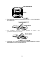
2) Clip the metal ceiling bracket to a suitably located ceiling tile separator.
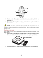
3) Slide the moveable section into place and tighten the screw (found
underneath) to secure it.
4) Position the AP so that the two tabs from the ceiling bracket can be inserted in
the slots in the AP.

8
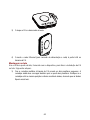
5) Slide the slider across to lock the AP to the bracket.
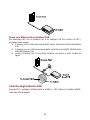
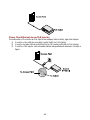
Connecting Power
This section describes how to power the AP in the following ways:
z By Power over Ethernet (PoE) supplied over the LAN by an 802.3af PoE
compliant device such as a switch.
z By PoE supplied by a PoE injector or midspan (not included with the AP).
: The PoE injector needs to be separately purchased.
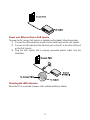
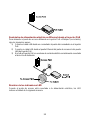
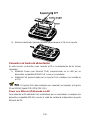
Power over Ethernet (PoE) from the LAN
To power the AP using PoE provided by a switch or other 802.3af compliant device,
plug the network cable from the device into the AP’s Ethernet port.

9
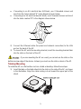
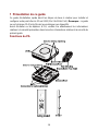
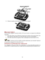
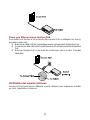
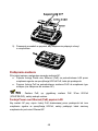
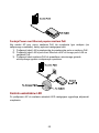
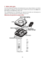
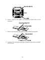
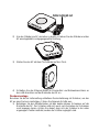
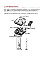
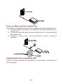
Power over Ethernet from a PoE Injector
To power the AP using a PoE injector or midspan (not included), follow these steps:
1) Connect the LAN cable from a switch to the Switch port on the PoE injector.
2) Connect a LAN cable from the Ethernet port on the AP to the other LAN port
on the PoE injector.
3) Plug the PoE injector into a properly grounded electric outlet. See the
illustration.
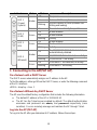
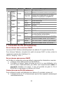
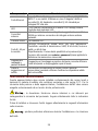
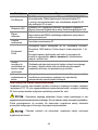
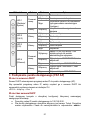
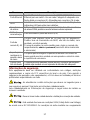
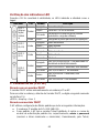
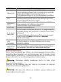
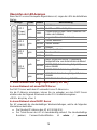
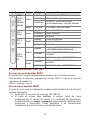
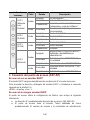
Checking the LED Indicators
When the AP is connected to power, LEDs indicate activity as follows:

10
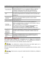
Indicator Color State Description
Off No power
On Failure of CPU or system
Amber
Blinking
System initiation or reset (software self-
testing and loading)
LED 1
(Power/
System)
Green On Powered on and ready for operation
Off Radio disabled
On Radio enabled
LED 2
(2.4G)
Green
Blinking Activity
Off Radio disabled
On Radio enabled
LED 3
(5G)
Green
Blinking Activity
Off
No 10/100/1000 BASE-T link detected, or
administratively disabled
On 10/100 BASE-T link detected; no activity
Amber
Blinking 10/100 BASE-T link activity
On 1000 BASE-T link detected; no activity
LED 4
(Ethernet)
Green
Blinking 1000 BASE-T link activity
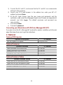
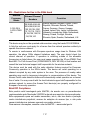
3 Connecting to the AP(FAT AP)
On a Network with a DHCP Server
The DHCP server automatically assigns an IP address to the AP.
To find the address, either get it from the DHCP Server, or enter the following command
at the CLI interface:
<9552> display vlan 1
On a Network Without Any DHCP Server
The AP uses the default factory configuration that includes the following information.
z The default IP address of the AP is 192.168.0.50.
z The AP has the Telnet server enabled by default. The default authentication
username and password are admin, and password respectively (case
sensitive). You can remotely manage and maintain the AP through Telnet.
Log into the AP (FAT AP)
To Log into the AP after you determine its IP address, follows these steps:

11
1) Connect the AP and PC, and ensure that the PC and AP can communicate
with each other properly.
2) Launch your PC’s web browser. In the address bar, enter your AP’s IP
address and press Enter.
3) At the AP Login Screen, type the user name and password, and the
verification code, select the language (English and Chinese are supported at
present), and click Login. The default username and password are
case-sensitive:
z Username: admin
z Password: password
Converting your Stand-alone AP (FAT) to a Managed AP (FIT)
If you plan to run this AP in Managed AP mode with a wireless controller, go to the web
page http://www.3com.com to get the instructions.
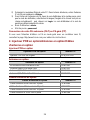
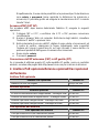
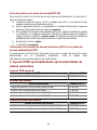
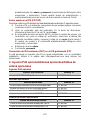
4 Optional
Optional POE injector
Optional POE injector 3C Number
802.3af Gigabit POE injector 3CNJPSE-GIG
Optional Antennas
Optional Antennas 3C Number
2dBi Dual-Band Omni Antenna Kit 3CWE590
6/8dBi Dual-Band Omni Antenna 3CWE591
18/20dBi Dual-Band Panel Antenna 3CWE596
8/10dBi Dual-Band Panel Antenna 3CWE598
Optional Antenna Cables
Optional Antenna Cables 3C Number
Ultra Low Loss 6 Foot Antenna Cable 3CWE580
Ultra Low Loss 20-Foot Antenna Cable 3CWE581
Ultra Low Loss 50-Foot Antenna Cable 3CWE582
R-SMA to SMA 6” Antenna Cable 3CWE586

12
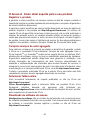
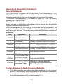
Appendix A Obtaining Support for your Product
Register
Your
Product
Warranty and other service benefits start from the date of purchase, so it is
important to register your product quickly to ensure you get full use of the
warranty and other service benefits available to you.
Warranty and other service benefits are enabled through product registration.
Register your product at http://eSupport.3com.com/. 3Com eSupport
services are based on accounts that you create or have authorization to
access. First time users must apply for a user name and password that
provides access to a number of eSupport features including Product
Registration, Repair Services, and Service Request. If you have trouble
registering your product, please contact 3Com Global Services for
assistance.
Purchase
Value
-
Added
Services
To enhance response times or extend warranty benefits, contact 3Com or
your authorized 3Com reseller. Value-added services like 3Com Express
SM
and Guardian
SM
can include 24x7 telephone technical support, software
upgrades, onsite assistance or advance hardware replacement.
Experienced engineers are available to manage your installation with
minimal disruption to your network. Expert assessment and implementation
services are offered to fill resource gaps and ensure the success of your
networking projects. More information on 3Com maintenance and
Professional Services is available at http://www.3com.com/
Contact your authorized 3Com reseller or 3Com for a complete list of the
value-added services available in your area.
Troubleshoot
Online
You will find support tools posted on the 3Com web site at
http://www.3com.com/
3Com Knowledgebase helps you troubleshoot 3Com products. This
query-based interactive tool is located at http://knowledgebase.3com.com
and contains thousands of technical solutions written by 3Com support
engineers.
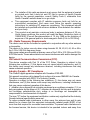
Access Software Downloads
Software Updates are the bug fix / maintenance releases for the version of
software initially purchased with the product. In order to access these
Software Updates you must first register your product on the 3Com web site
at http://eSupport.3com.com/

13
First time users will need to apply for a user name and password. A link to
software downloads can be found at http://eSupport.3com.com/, or under
the Product Support heading at http://www.3com.com/
Software Upgrades are the software releases that follow the software
version included with your original product. In order to access upgrades and
related documentation you must first purchase a service contract from 3Com
or your reseller.
Telephone Technical Support and Repair
To enable telephone support and other service benefits, you must first
register your product at http://eSupport.3com.com/
Warranty and other service benefits start from the date of purchase, so it is
important to register your product quickly to ensure you get full use of the
warranty and other service benefits available to you.
When you contact 3Com for assistance, please have the following
information ready:
z Product model name, part number, and serial number
z Proof of purchase, if you have not pre-registered your product
z A list of system hardware and software, including revision level
z Diagnostic error messages
z Details about recent configuration changes, if applicable
To send a product directly to 3Com for repair, you must first obtain a return
authorization number (RMA). Products sent to 3Com, without authorization
numbers clearly marked on the outside of the package, will be returned to the
sender unopened, at the sender’s expense. If your product is registered and
under warranty, you can obtain an RMA number online at
http://eSupport.3com.com/. First time users will need to apply for a user
name and password.
Contact Us
3Com offers telephone, e-mail and internet access to technical support and
repair services. To access these services for your region, use the appropriate
telephone number, URL or e-mail address.
Find a current directory of contact information posted on the 3Com web site
at http://csoweb4.3com.com/contactus/.

14
1 Présentation de ce guide
Ce guide d'installation rapide décrit les étapes de base à réaliser pour installer et
configurer votre point d'accès 3Com 9552 (11n 2.4+5GHz PoE). Remarque : ce guide
se sert du terme PA (Point d'Accès) pour désigner ces dispositifs.
Avant d'installer ou de déplacer le PA, veuillez lire attentivement les informations
relatives à la sécurité présentées dans la section
Informations relatives à la sécurité du
présent guide.
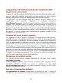
Fonctions du PA

15
Fonction Description
Port Ethernet
Le port Ethernet offre une connexion Ethernet 10/100/1000
BASE-T à un commutateur. Utilisez un câble droit de catégorie 5
et des connecteurs RJ45 standard pour relier le PA au réseau.
Voyants
Les voyants indiquent si le dispositif est sous tension et si des
activités sont en cours. Reportez-vous à la section
Vérification
des voyants lumineux pour plus d'informations.
Connecteurs
d'antenne
Le PA dispose de trois antennes intégrées. En outre, trois
connecteurs d'antenne RSMA permettent de brancher des
antennes externes supplémentaires.
Bouton de
réinitialisation
Pour réinitialiser le PA.
Port pour la
console RJ45
Ce port fournit une interface série au PA à des fins de diagnostic.
Par défaut : Fréquence de baud de 9600, 8 bits de données,
aucune parité, un bit d'arrêt.
Le nom d'utilisateur et le mot de passe par défaut associés à
l'ouverture de session dans la console sont respectivement
admin
et
password
(sensible à la casse)
Attache de
montage mural et
socle de bureau
La combinaison attache et socle permet de fixer le dispositif au
mur ou sur une table.
Support
suspendu au
plafond
Le support suspendu au plafond (support de plafond et coulisse)
vous permet de monter l'appareil sur un séparateur de
carrelages de plafond adéquat.
Informations relatives à la sécurité
Cet équipement doit être installé conformément aux normes de construction locales et
nationales, aux restrictions réglementaires et au règlement du FCC. Pour garantir la
sécurité des personnes et des équipements, seul le personnel chargé de la gestion du
réseau est autorisé à procéder à l'installation du PA.
: Ces avertissements contiennent des instructions que vous devez
impérativement suivre pour votre propre sécurité. Respectez strictement toutes les instructions.
Lisez attentivement les informations de sécurité suivantes avant d'installer ou de
désinstaller le dispositif.

16
: Faites preuve de la plus grande attention lors des opérations
d'installation et de désinstallation de l'unité.
: Cette unité fonctionne sur très basse tension conformément à la
norme IEC60950-1. Ces conditions ne sont respectées que si l'équipement auquel
l'appareil est raccordé fonctionne également sous très basse tension.
: L'unité ne contient ni fusibles, ni pièces nécessitant un entretien
particulier. Si vous rencontrez un problème que vous ne parvenez pas à résoudre en
suivant les mesures correctives proposées dans ce guide, contactez votre fournisseur.
: Ports RJ45. Il s'agit de sockets de données RJ45. Ces sockets ne
peuvent en aucun cas être utilisés comme prises de téléphone standard ou pour
connecter le dispositif à un autocommutateur privé classique ou un réseau
téléphonique public. Branchez uniquement des connecteurs de données RJ45, des
systèmes de téléphonie en réseau ou des téléphones en réseau à ces sockets.
Il est possible de brancher des câbles de données blindés ou non blindés équipés de
prises blindées ou non blindées à ces sockets de données.
: Conformément aux dispositions relatives à l'exposition aux
radiofréquences du règlement du FCC, il convient de se tenir à une distance minimale
de 20 cm de l'antenne lorsque le PA est en fonctionnement.
Canaux approuvés
Ce produit peut être utilisé uniquement sur une plage limitée de canaux, propre à
chaque pays. Pour assurer une installation correcte, sélectionnez votre pays dans la
liste.
En vertu des restrictions du FCC, du Canada, de l'Europe et d'autres pays, il se peut
que les canaux disponibles soient limités au niveau de votre produit, tel qu'il vous est
livré. Si d'autres canaux sont autorisés dans votre pays, consultez le site Web 3Com
pour obtenir la dernière version du logiciel. L'annexe A répertorie les informations
relatives au téléchargement de logiciel.

17
2 Déballage du PA
Déballage du PA
Vérifiez que vous disposez bien des éléments suivants, fournis avec le PA:
z Un point d'accès 3Com 9552
z Matériel pour la fixation murale:
z Un ensemble attache murale et socle
z Quatre vis
z Quatre fixations murales
z Support suspendu au plafond :
z Un support de plafond
z Une coulisse
z Deux vis
z Huit pieds autocollants en caoutchouc
z Une copie de ce Guide de mise en route
z Un certificat de garantie 3Com
z Un câble de console
Préparation de l'installation
3Com recommande de mettre l'équipement sous tension, de vérifier le branchement
du câble Ethernet et de s'assurer que les voyants fonctionnent avant d'installer le PA
dans un emplacement difficile d'accès. Vérifiez également les points suivants avant de
fixer ou de connecter le PA:
Fonction Description
Port du
commutateur
Pour relier votre réseau sans fil à votre réseau câblé, vous devez
connecter un commutateur au PA.
Câblage
Vérifiez que le site est équipé d'un câble droit Ethernet standard
avant d'installer le PA .
Assurez-vous qu'il s'agit d'un câble très souple et que le connecteur
RJ45 passe sans encombre dans l'encoche de l'attache.
Alimentation
L'alimentation est assurée par un appareil PoE de norme 802.3af tel
qu'un commutateur PoE ou un injecteur PoE. Pour des performances
optimales, 3Com préconise l'utilisation d'un lien gigabit.
Adresse
MAC
Notez l'adresse MAC du PA pour référence ultérieure avant d'installer
le PA dans un emplacement difficile d'accès.
Cette adresse MAC est imprimée à l'arrière du PA..
La pagina si sta caricando...
La pagina si sta caricando...
La pagina si sta caricando...
La pagina si sta caricando...
La pagina si sta caricando...
La pagina si sta caricando...
La pagina si sta caricando...
La pagina si sta caricando...
La pagina si sta caricando...
La pagina si sta caricando...
La pagina si sta caricando...
La pagina si sta caricando...
La pagina si sta caricando...
La pagina si sta caricando...
La pagina si sta caricando...
La pagina si sta caricando...
La pagina si sta caricando...
La pagina si sta caricando...
La pagina si sta caricando...
La pagina si sta caricando...
La pagina si sta caricando...
La pagina si sta caricando...
La pagina si sta caricando...
La pagina si sta caricando...
La pagina si sta caricando...
La pagina si sta caricando...
La pagina si sta caricando...
La pagina si sta caricando...
La pagina si sta caricando...
La pagina si sta caricando...
La pagina si sta caricando...
La pagina si sta caricando...
La pagina si sta caricando...
La pagina si sta caricando...
La pagina si sta caricando...
La pagina si sta caricando...
La pagina si sta caricando...
La pagina si sta caricando...
La pagina si sta caricando...
La pagina si sta caricando...
La pagina si sta caricando...
La pagina si sta caricando...
La pagina si sta caricando...
La pagina si sta caricando...
La pagina si sta caricando...
La pagina si sta caricando...
La pagina si sta caricando...
La pagina si sta caricando...
La pagina si sta caricando...
La pagina si sta caricando...
La pagina si sta caricando...
La pagina si sta caricando...
La pagina si sta caricando...
La pagina si sta caricando...
La pagina si sta caricando...
La pagina si sta caricando...
La pagina si sta caricando...
La pagina si sta caricando...
La pagina si sta caricando...
La pagina si sta caricando...
La pagina si sta caricando...
La pagina si sta caricando...
La pagina si sta caricando...
La pagina si sta caricando...
La pagina si sta caricando...
La pagina si sta caricando...
La pagina si sta caricando...
La pagina si sta caricando...
La pagina si sta caricando...
La pagina si sta caricando...
La pagina si sta caricando...
La pagina si sta caricando...
La pagina si sta caricando...
La pagina si sta caricando...
La pagina si sta caricando...
La pagina si sta caricando...
La pagina si sta caricando...
La pagina si sta caricando...
La pagina si sta caricando...
La pagina si sta caricando...
La pagina si sta caricando...
La pagina si sta caricando...
La pagina si sta caricando...
La pagina si sta caricando...
La pagina si sta caricando...
La pagina si sta caricando...
La pagina si sta caricando...
La pagina si sta caricando...
La pagina si sta caricando...
La pagina si sta caricando...
La pagina si sta caricando...
La pagina si sta caricando...
La pagina si sta caricando...
La pagina si sta caricando...
La pagina si sta caricando...
La pagina si sta caricando...
La pagina si sta caricando...
La pagina si sta caricando...
La pagina si sta caricando...
La pagina si sta caricando...
La pagina si sta caricando...
La pagina si sta caricando...
-
 1
1
-
 2
2
-
 3
3
-
 4
4
-
 5
5
-
 6
6
-
 7
7
-
 8
8
-
 9
9
-
 10
10
-
 11
11
-
 12
12
-
 13
13
-
 14
14
-
 15
15
-
 16
16
-
 17
17
-
 18
18
-
 19
19
-
 20
20
-
 21
21
-
 22
22
-
 23
23
-
 24
24
-
 25
25
-
 26
26
-
 27
27
-
 28
28
-
 29
29
-
 30
30
-
 31
31
-
 32
32
-
 33
33
-
 34
34
-
 35
35
-
 36
36
-
 37
37
-
 38
38
-
 39
39
-
 40
40
-
 41
41
-
 42
42
-
 43
43
-
 44
44
-
 45
45
-
 46
46
-
 47
47
-
 48
48
-
 49
49
-
 50
50
-
 51
51
-
 52
52
-
 53
53
-
 54
54
-
 55
55
-
 56
56
-
 57
57
-
 58
58
-
 59
59
-
 60
60
-
 61
61
-
 62
62
-
 63
63
-
 64
64
-
 65
65
-
 66
66
-
 67
67
-
 68
68
-
 69
69
-
 70
70
-
 71
71
-
 72
72
-
 73
73
-
 74
74
-
 75
75
-
 76
76
-
 77
77
-
 78
78
-
 79
79
-
 80
80
-
 81
81
-
 82
82
-
 83
83
-
 84
84
-
 85
85
-
 86
86
-
 87
87
-
 88
88
-
 89
89
-
 90
90
-
 91
91
-
 92
92
-
 93
93
-
 94
94
-
 95
95
-
 96
96
-
 97
97
-
 98
98
-
 99
99
-
 100
100
-
 101
101
-
 102
102
-
 103
103
-
 104
104
-
 105
105
-
 106
106
-
 107
107
-
 108
108
-
 109
109
-
 110
110
-
 111
111
-
 112
112
-
 113
113
-
 114
114
-
 115
115
-
 116
116
-
 117
117
-
 118
118
-
 119
119
-
 120
120
-
 121
121
-
 122
122


3com AP9552 Hardware Installation Manual
- Tipo
- Hardware Installation Manual
in altre lingue
- English: 3com AP9552
- français: 3com AP9552
- español: 3com AP9552
- Deutsch: 3com AP9552
- português: 3com AP9552
- polski: 3com AP9552
Documenti correlati
-
3com Model WL-604 Manuale utente
-
-
-
-
-
3com 4210 26-PORT Manuale utente
-
-
3com 3CRWE675075 - 11a/b/g Wireless LAN Workgroup Bridge Manuale utente
-
Altri documenti
-
H3C WA2620-AGN Guida Rapida
-
Alcatel Temporis IP251G Manuale del proprietario
-
Alcatel Temporis IP901G Manuale del proprietario
-
Digitus DN-95359 Guida Rapida
-
Klipsch GIG XL Manuale utente
-
Shure PA805Z2-RSMA Guida utente
-
TP-LINK TL-WA5210G V2 Manuale del proprietario
-
LevelOne POI-3000 Quick Installation Manual
-
Klipsch GIG XXL Manuale utente
-
Kingston Technology Computer Drive DT4000M-R Manuale utente