
H3C WA2620-AGN WLAN Access Point
Quick Start
Hangzhou H3C Technologies Co., Ltd.
Manual Version: APW101-20090729
BOM:3122A08S

Copyright © 2009, Hangzhou H3C Technologies Co., Ltd. and its
licensors
H3C Technologies Co., Ltd., a subsidiary of 3Com Corporation.
All Rights Reserved
No part of this manual may be reproduced or transmitted in any form
or by any means without prior written consent of Hangzhou H3C
Technologies Co., Ltd.
Trademarks
H3C, , Aolynk, , H
3
Care,
, TOP G, ,
IRF, NetPilot, Neocean, NeoVTL, SecPro, SecPoint, SecEngine,
SecPath, Comware, Secware, Storware, NQA, VVG, V
2
G, V
n
G,
PSPT, XGbus, N-Bus, TiGem, InnoVision and HUASAN are
trademarks of Hangzhou H3C Technologies Co., Ltd.
All other trademarks that may be mentioned in this manual are the
property of their respective owners.
Notice
The information in this document is subject to change without notice.
Every effort has been made in the preparation of this document to
ensure accuracy of the contents, but all statements, information, and
recommendations in this document do not constitute the warranty of
any kind, express or implied.

About This Manual
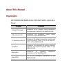
Organization
H3C WA2620-AGN WLAN Access Point Quick Start is organized as
follows:
Chapter Contents
1 About This Guide
Introduces the AP features, safety information,
and approved channels of the WA2620-AGN.
2 Mounting the AP
Introduces the installation, power supply
connection of the WA2620-AGN.
3 Connecting to the AP
Introduces the network connection, log into and
how to convert AP from FIT to FAT or from FAT
to FIT of the WA2620-AGN.
4 Optional
Introduces the optional POE injector, optional
antennas and optional antenna cables of the
WA2620-AGN.
Appendix A
Introduces the regulatory compliance
information of the WA2620-AGN.
Appendix B
List of the hazardous substances of the
WA2620-AGN.

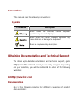
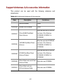
Conventions
The manual uses the following conventions:
Symbols
Convention Description
Means reader be extremely careful. Improper
operation may cause bodily injury.
Means reader be careful. Improper operation may
cause data loss or damage to equipment.
Means a complementary description.
Obtaining Documentation and Technical Support
To obtain up-to-date documentation and technical support, go to
http://www.h3c.com and select your country or region. Depending
on your selection, you will be redirected to either of the following
websites:
At http://www.h3c.com
Documentation
Go to the following columns for different categories of product
documentation:

[Products & Solutions]: Provides information about products and
technologies, as well as solutions.
[Technical Support & Document > Technical Documents]: Provides
several categories of product documentation, such as installation
and configuration.
[Technical Support & Document > Software Download]: Provides the
documentation released with the software version.
Technical Support
customer_service@h3c.com
http://www.h3c.com
At http://www.h3cnetworks.com
Documentation
1) Select Drivers & Downloads in the Support area.
2) Select Documentation for Type of File and select Product
Category.
Technical Support
Register Your Product
Warranty and other service benefits start from the date of purchase,
so it is important to register your product quickly to ensure you get
full use of the warranty and other service benefits available to you.
Warranty and other service benefits are enabled through product
registration. Register your product at
http://www.h3cnetworks.com, go to Support, Product

Registration. Support services are based on accounts that you
create or have authorization to access. First time users must apply
for a user name and password that provides access to a number of
eSupport features including Product Registration, Repair Services,
and Service Request. If you have trouble registering your product,
please contact 3Com Global Services for assistance.
Purchase Value-Added Services
To enhance response times or extend warranty benefits, contact
3Com or your authorized reseller. Value-added services like
Express
SM
and Guardian
SM
can include 24x7 telephone technical
support, software upgrades, onsite assistance or advance hardware
replacement. Experienced engineers are available to manage your
installation with minimal disruption to your network. Expert
assessment and implementation services are offered to fill resource
gaps and ensure the success of your networking projects. More
information on 3Com maintenance and Professional Services is
available at http://www.h3cnetworks.com.
Contact your authorized reseller or 3Com for a complete list of the
value-added services available in your area.
Troubleshoot Online
You will find support tools posted on the web site at
http://www.h3cnetworks.com/ under Support, Knowledgebase.
The Knowledgebase helps you troubleshoot H3C products. This
query-based interactive tool contains thousands of technical
solutions.

Access Software Downloads
Software Updates are the bug fix / maintenance releases for the
version of software initially purchased with the product. In order to
access these Software Updates you must first register your product
on the web site at http://www.h3cnetworks.com, go to Support,
Product Registration.
First time users will need to apply for a user name and password. A
link to software downloads can be found at
http://www.h3cnetworks.com, under Support, Drivers and
downloads.
Software Upgrades are the software releases that follow the
software version included with your original product. In order to
access upgrades and related documentation you must first purchase
a service contract from 3Com or your reseller.
Telephone Technical Support and Repair
To enable telephone support and other service benefits, you must
first register your product at http://www.h3cnetworks.com/
Warranty and other service benefits start from the date of purchase,
so it is important to register your product quickly to ensure you get
full use of the warranty and other service benefits available to you.
When you contact 3Com for assistance, please have the following
information ready:
z Product model name, part number, and serial number
z Proof of purchase, if you have not pre-registered your product
z A list of system hardware and software, including revision level

z Diagnostic error messages
z Details about recent configuration changes, if applicable
To send a product directly to 3Com for repair, you must first obtain a
return authorization number (RMA). Products sent to 3Com, without
authorization numbers clearly marked on the outside of the package,
will be returned to the sender unopened, at the sender’s expense. If
your product is registered and under warranty, you can obtain an
RMA number online at http://www.h3cnetworks.com under
support, Repair & Replacement Request. First time users will
need to apply for a user name and password.
Contact Us
3Com offers telephone, e-mail and internet access to technical
support and repair services. To access these services for your
region, use the appropriate telephone number, URL or e-mail
address.
Find a current directory of contact information posted on the web site
at http://www.h3cnetworks.com under Support, Technical
Support Contact.
Documentation Feedback
You can e-mail your comments about product documentation to
We appreciate your comments.

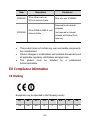
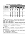
Environmental Protection
This product has been designed to comply with the requirements on
environmental protection. For the proper storage, use and disposal
of this product, national laws and regulations must be observed.

i
Table of Contents
1 About This Guide..................................................................................1-1
AP Features .......................................................................................1-1
Safety Information..............................................................................1-3
Approved Channels............................................................................1-4
2 Mounting the AP ...................................................................................2-1
Unpacking the AP ..............................................................................2-1
Preparing for Installation....................................................................2-1
Mounting the AP.................................................................................2-2
Wall or Electrical Box Mounting..................................................2-3
Tabletop Mounting......................................................................2-4
Ceiling Mounting.........................................................................2-5
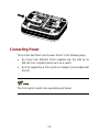
Connecting Power..............................................................................2-8
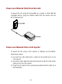
Power over Ethernet (PoE) from the LAN..................................2-9
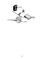
Power over Ethernet from a PoE Injector...................................2-9
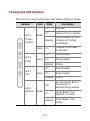
Checking the LED Indicators....................................................2-11
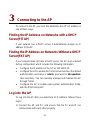
3 Connecting to the AP...........................................................................3-1
Finding the IP Address on Networks with a DHCP Server(FIT AP).........3-1
Finding the IP Address on Networks Without a DHCP Server(FAT AP).....3-1
Log into the AP...................................................................................3-1
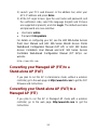
Converting your Managed AP (FIT) to a Stand-alone AP (FAT) .......3-2
Converting your Stand-alone AP (FAT) to a Managed AP (FIT) .......3-2
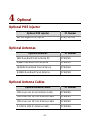
4 Optional .................................................................................................4-1
Optional POE injector.........................................................................4-1
Optional Antennas..............................................................................4-1
Optional Antenna Cables...................................................................4-1

1-1
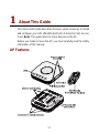
1 About This Guide
This Quick Start Guide describes the basic steps necessary to install
and configure your H3C WA2620-AGN (11n 2.4+5GHz PoE) Access
Point. Note: This guide refers to these devices as the AP.
Before you install or move the AP, you must carefully read the safety
information of this manual.
AP Features

1-2
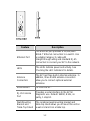
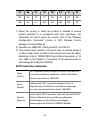
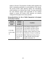
Feature Description
Ethernet Port
The Ethernet port provides a 10/100/1000
BASE-T Ethernet connection to a switch. Use
a suitable Category 5 cable with
straight-through wiring and standard RJ-45
connectors to connect your AP to the network.
LEDs
The LEDs indicate power and activity. See
Checking the LED Indicators for details.
Antenna
Connectors
The AP has three built-in internal antennas. In
addition, three RSMA antenna connectors
allow you to connect optional external
antennas.
Reset Button To reset the AP.
RJ-45 Console
Port
Provides a serial interface to the AP for
diagnostic use. Default: 9600K, 8 bits, no
parity, 1 stop bit.
Wall-Mounting
Bracket and
Table-Top Stand
The combined wall-mounting bracket and
table-top stand allows you to mount the unit on
a wall or stand it on a table top.

1-3
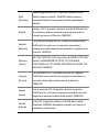
Feature Description
Suspended
ceiling bracket
The Suspended ceiling bracket (Ceiling
bracket and Slider) allows you to mount the
unit on a suitably ceiling tile separator.
Security slot
Dimensions (length x width x depth): 7 x 3 x 4
mm (0.28 x 0.12 x 0.16 in.) ,and a standard
Kensington lock is recommended.
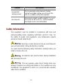
Safety Information
This equipment must be installed in compliance with local and
national building codes, regulatory restrictions, and FCC rules. For
the safety of people and equipment, only professional network
personnel should install the AP.
: Warnings contain directions that you must follow for
your personal safety. Follow all directions carefully.
You must read the following safety information carefully before you
install or remove the unit.
: Exceptional care must be taken during installation
and removal of the unit.
: This unit operates under SELV (Safety Extra Low
Voltage) conditions according to IEC60950-1. The conditions are only
maintained if the equipment to which it is connected also operates
under SELV conditions.

1-4
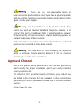
: There are no user-replaceable fuses or
user-serviceable parts inside the unit. If you have a physical problem
with the unit that cannot be solved with problem solving actions in this
guide, contact your supplier.
: RJ-45 ports. These are RJ-45 data sockets. They
cannot be used as standard traditional telephone sockets, or to
connect the unit to a traditional PBX or public telephone network.
Only connect RJ-45 data connectors, network telephony systems, or
network telephones to these sockets.
Either shielded or unshielded data cables with shielded or unshielded
jacks can be connected to these data sockets.
: To comply with FCC radio frequency (RF) exposure
limits, a minimum body-to-antenna distance of 20 cm must be
maintained when the AP is operational.
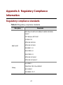
Approved Channels
Use of this product is only authorized for the channels approved by
each country. For proper installation, select your country from the
country-selection list.
To conform to FCC and other country restrictions, your product may
be limited in the channels that are available. If other channels are
permitted your country, please visit the web site for the latest software
version:
http://www.h3c.com

2-1
2 Mounting the AP
Unpacking the AP
Make sure that you have the following items, which are included with
the AP:
z One H3C WA2620-AGN Access Point
z Wall-mounting hardware:
z One combined wall-mounting bracket and table-top stand
z Four screws
z Four wall anchors
z Suspended ceiling bracket:
z One ceiling bracket
z One slider
z Two screws
z Eight adhesive rubber feet
z One copy of this Quick Start Guide
z One H3C Warranty Flyer
z One console cable
Preparing for Installation
H3C recommends that you connect and check the Ethernet cable and
LEDs before you install the AP in a hard-to-reach location. Also,
observe these items before you mount or connect the AP:

2-2
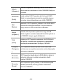
Feature Description
Switch Port
To connect your wireless network to your wired
network, you need a switch that is connected to
the AP.
Cabling
Make sure that a standard Ethernet cable with
straight-through wiring is installed at the site
before you install the AP.
Make sure that the cable is highly flexible and that
the RJ-45 connector has no extra covering that
could prevent the cable from being routed through
the mounting bracket.
Power
Requirement
Power is supplied using an 802.3af Power Over
Ethernet (PoE) compliant device such as a PoE
switch or a PoE injector. For maximum
performance, H3C recommends that you use a
Gigabit link.
MAC
Address
Record the AP MAC address in a safe place
before the AP is installed in a hard-to-reach
location.
The MAC address is printed on the back of the AP.
Mounting the AP
The AP can be mounted on the following types of surfaces:
z Wall or electrical box (NEMA enclosure)
z Table top
z Ceiling Mounting

2-3
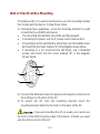
Wall or Electrical Box Mounting
To install your AP on a wall or electrical box, use the mounting bracket
that comes with the device. Follow these steps:
1) Following these guidelines, screw the mounting bracket to a wall
or electrical box (NEMA enclosure):
z The mounting bracket tabs should be pointing upward.
z If mounting to drywall, use the 4 screws and 4 wall anchors.
z If mounting to an EU electrical box (60.3mm), use 2 threaded screws
and insert into the holes marked “A” in the diagram shown below.
z If mounting to a US electrical box (83.3mm), use 2 threaded
screws and insert into the holes marked “B” in the diagram
shown below.
A
B
A
B
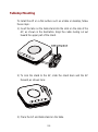
2) Connect the Ethernet cable (for power and network connection) to
the LAN port on the back of the AP.
3) To mount the AP onto the mounting bracket, insert the
mounting-bracket tabs into the slots on the back of the AP.
: If you are mounting the AP on a wall, you cannot use
the slots on the bottom narrow edge of the device. Instead, you must
use the slots on back of the AP.

2-4
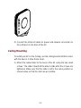
Tabletop Mounting
To install the AP on a flat surface such as a table or desktop, follow
these steps:
1) Insert the tabs on the table stand into the slots on the side of the
AP, as shown in the illustration. Align the cable routing cut out
toward the upper part of the stand.
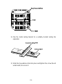
2) To lock the stand to the AP, slide the stand back and the AP
forward, as shown here:
3) Place the AP and table stand on the table.

2-5
4) Connect the Ethernet cable for power and network connection to
the LAN port on the back of the AP.
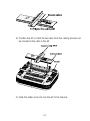
Ceiling Mounting
To install your AP on the Ceiling, use the ceiling bracket kit that comes
with the device. Follow these steps:
1) Attach the metal slider to the back of the AP using the two small
screws. The slider should still be able to slide after the screws are
tightened, Make sure that the slide is left in the same position as
shown below so that the slots are accessible.

2-6
2) Clip the metal ceiling bracket to a suitably located ceiling tile
separator.
3) Slide the moveable section into place and tighten the screw (found
underneath) to secure it.
La pagina si sta caricando...
La pagina si sta caricando...
La pagina si sta caricando...
La pagina si sta caricando...
La pagina si sta caricando...
La pagina si sta caricando...
La pagina si sta caricando...
La pagina si sta caricando...
La pagina si sta caricando...
La pagina si sta caricando...
La pagina si sta caricando...
La pagina si sta caricando...
La pagina si sta caricando...
La pagina si sta caricando...
La pagina si sta caricando...
La pagina si sta caricando...
La pagina si sta caricando...
La pagina si sta caricando...
La pagina si sta caricando...
La pagina si sta caricando...
La pagina si sta caricando...
La pagina si sta caricando...
La pagina si sta caricando...
La pagina si sta caricando...
La pagina si sta caricando...
-
 1
1
-
 2
2
-
 3
3
-
 4
4
-
 5
5
-
 6
6
-
 7
7
-
 8
8
-
 9
9
-
 10
10
-
 11
11
-
 12
12
-
 13
13
-
 14
14
-
 15
15
-
 16
16
-
 17
17
-
 18
18
-
 19
19
-
 20
20
-
 21
21
-
 22
22
-
 23
23
-
 24
24
-
 25
25
-
 26
26
-
 27
27
-
 28
28
-
 29
29
-
 30
30
-
 31
31
-
 32
32
-
 33
33
-
 34
34
-
 35
35
-
 36
36
-
 37
37
-
 38
38
-
 39
39
-
 40
40
-
 41
41
-
 42
42
-
 43
43
-
 44
44
-
 45
45


in altre lingue
- English: H3C WA2620-AGN Quick start guide
Documenti correlati
Altri documenti
-
3com AP9552 Hardware Installation Manual
-
-
-
-
-
Cisco MERAKI MR72 Guida d'installazione
-
-
-
Moulinex ME204131 Manuale utente
-
 Cambium Networks XV2-2T Manuale utente
