
Part Number 10016854 Rev. AA
Published May 2008
Quick Start Guide
3Com
®
AirConnect
®
9550
11n 2.4+5GHz PoE Access Point
3CRWE955075 / WL-605
3Com
®
AirConnect
®
9150
11n 2.4GHz PoE Access Point
3CRWE915075 / WL-604
Guide de mise en route…11
Français
Guida introduttiva…21
Italiano
Kurzanleitung…31
Deutsch
Guía de inicio rápido…41
Español
Guia de Início Rápido…51
Portuguese

Copyright © 2008, 3Com Corporation. All rights reserved. No part of this documentation may be reproduced in
any form or by any means or used to make any derivative work (such as translation, transformation, or
adaptation) without written permission from 3Com Corporation.
3Com Corporation reserves the right to revise this documentation and to make changes in content from time to
time without obligation on the part of 3Com Corporation to provide notification of such revision or change.
3Com Corporation provides this documentation without warranty, term, or condition of any kind, either implied
or expressed, including, but not limited to, the implied warranties, terms, or conditions of merchantability,
satisfactory quality, and fitness for a particular purpose. 3Com may make improvements or changes in the
product(s) and/or the program(s) described in this documentation at any time.
If there is any software on removable media described in this documentation, it is furnished under a license
agreement included with the product as a separate document, in the hardcopy documentation, or on the
removable media in a directory file named LICENSE.TXT or !LICENSE.TXT. If you are unable to locate a copy,
please contact 3Com and a copy will be provided to you.
UNITED STATES GOVERNMENT LEGENDS:
If you are a United States government agency, then this documentation and the software described herein are
provided to you subject to the following:
United States Government Legend: All technical data and computer software is commercial in nature and
developed solely at private expense. Software is delivered as Commercial Computer Software as defined in
DFARS 252.227-7014 (June 1995) or as a commercial item as defined in FAR
2.101(a) and as such is provided
with only such rights as are provided in 3Com’s standard commercial license for the Software. Technical data is
provided with limited rights only as provided in DFAR 252.227-7015 (Nov 1995) or FAR
52.227-14 (June 1987),
whichever is applicable. You agree not to remove or deface any portion of any legend provided on any licensed
program or documentation contained in, or delivered to you in conjunction with guide.
Unless otherwise indicated, 3Com registered trademarks are registered in the United States and may or may not
be registered in other countries.
3Com, the 3Com logo, and AirConnect are registered trademarks of 3Com Corporation.
Microsoft and Windows are either registered trademarks or trademarks of Microsoft Corporation in the United
States and/or other countries. Oracle is a registered trademark of Oracle Corporation.
All other company, brand, and product names may be registered trademarks or trademarks of the respective
companies with which they are associated.

Quick Start Guide
3Com
®
AirConnect
®
9550
11n 2.4+5GHz PoE Access Point
3CRWE955075 / WL-605
3Com
®
AirConnect
®
9150 11n 2.4GHz PoE Access Point
3CRWE915075 / WL-604
This Quick Start Guide describes the basic steps necessary to install and configure your 3Com
AirConnect 9550 11n 2.4+5GHz PoE Access Point and 3Com AirConnect 9150 11n 2.4GHz PoE
Access Point. Note: This guide refers to these devices as the Access Point or AP.
Before you install or move the AP, you must carefully read the safety information provided in
“Safety Information” on page 3 of this manual.
About This Guide
This guide describes the basic installation of the AP. It covers these topics:
• AP Features
• Register Your Product for Services and Repair
• Safety Information
• 1: Unpacking the AP
• 2: Preparing for Installation
• 3: Mounting the AP
• 4: Connecting Power
• 5: Checking the LED Indicators
• 6: Installing Software
• 7: Connecting to the AP
• 8: Configuring the AP
• Troubleshooting

2
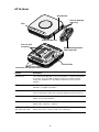
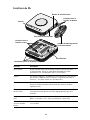
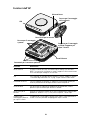
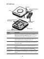
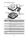
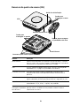
AP Features
Feature Description
Ethernet Port The Ethernet port provides a 10/100/1000 BASE-T Ethernet connection
to a switch. Use a suitable Category 5 cable with straight-through
wiring and standard RJ-45 connectors to connect your AP to the
network.
LEDs The LEDs indicate power and activity. See “Checking the LED
Indicators” on page 8 for details.
Antenna Connectors The AP has three built-in internal antennas. In addition, three RSMA
antenna connectors allow you to connect optional external antennas.
Reset Button To restore factory settings, during power-up, press the Reset button and
hold it for 5 or more seconds.
RJ-45 Console Port Provides a serial interface to the AP for diagnostic use. Default: 115.2K
speed, 8 bits, no parity, 1 stop bit.
Wall-Mounting Bracket
and Table-Top Stand
The combined wall-mounting bracket and table-top stand allows you to
mount the unit on a wall or stand it on a table top.
Ethernet Port
Wall Mounting Bracket/
Connectors for optional antennas
LEDs
RJ-45 Console Port
Reset Button
Table Top Stand
Slots for desktop
mounting
Slots for wall
mounting

3
Register Your Product for Services and Repair
To obtain telephone support as part of your warranty and other service benefits, you must first
register your product at:
http://eSupport.3com.com/
Telephone Technical Support and Repair
3Com offers telephone, e-mail, and Internet access to technical support and repair services. To
access these services for your region, use the appropriate telephone number, URL, or e-mail
address from the following URL:
http://csoweb4.3com.com/contactus/
Safety Information
This equipment must be installed in compliance with local and national building codes, regulatory
restrictions, and FCC rules. For the safety of people and equipment, only professional network
personnel should install the AP.
You must read the following safety information carefully before you install or remove the
unit.
Approved Channels
Use of this product is only authorized for the channels approved by each country. For proper
installation, select your country from the country-selection list.
To conform to FCC and other country restrictions, your product may be limited in the channels
that are available. If other channels are permitted in your country, please visit the 3Com web site
for the latest software version:
www.3Com.com
WARNING: Warnings contain directions that you must follow for your personal safety.
Follow all directions carefully.
WARNING: Exceptional care must be taken during installation and removal of the unit.
WARNING: This unit operates under SELV (Safety Extra Low Voltage) conditions
according to IEC
950 / IEC 60950. The conditions are only maintained if the equipment
to which it is connected also operates under SELV conditions.
WARNING: There are no user-replaceable fuses or user-serviceable parts inside the
unit. If you have a physical problem with the unit that cannot be solved with problem
solving actions in this guide, contact your supplier.
WARNING: RJ-45 ports. These are RJ-45 data sockets. They cannot be used as
standard traditional telephone sockets, or to connect the unit to a traditional PBX or
public telephone network. Only connect RJ-45 data connectors, network telephony
systems, or network telephones to these sockets.
Either shielded or unshielded data cables with shielded or unshielded jacks can be
connected to these data sockets.
WARNING: To comply with FCC radio frequency (RF) exposure limits, a minimum
body-to-antenna distance of 20 cm (8 in.) must be maintained when the AP is
operational.

4
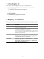
1. Unpacking the AP
Make sure that you have the following items, which are included with the AP:
• One 3Com AirConnect 9550 Access Point or 3Com AirConnect 9150 Access Point
• Wall-mounting hardware:
• 1 combined wall-mounting bracket and table-top stand
• 4 screws
• 4 wall anchors
• 8 adhesive rubber feet
• 1 CD-ROM containing the WIDMan Utility software
• 1 copy of this Quick Start Guide
• One 3Com Warranty document
2. Preparing for Installation
3Com recommends that you connect and check the Ethernet cable and LEDs before you install the
AP in a hard-to-reach location. Also, observe these items before you mount or connect the AP:
Feature Description
Switch Port To connect your wireless network to your wired network, you need a
switch that is connected to the AP.
Cabling Make sure that a standard Ethernet cable with straight-through wiring
is installed at the site before you install the AP.
Make sure that the cable is highly flexible and that the RJ-45 connector
has no extra covering that could prevent the cable from being routed
through the mounting bracket.
Power Requirement Power is supplied using an 802.3af Power Over Ethernet (PoE)
compliant device such as a PoE switch or a PoE injector (also called a
PoE midspan). Example: 3CNJPSE-GIG. For maximum performance,
3Com recommends that you use a Gigabit link.
MAC Address Record the AP MAC address in a safe place before the AP is installed in
a hard-to-reach location.
The MAC address is printed on the back of the AP. Additional MAC
address labels are shipped with the AP.

5
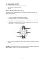
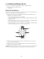
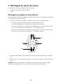
3. Mounting the AP
The AP can be mounted on the following types of surfaces:
• Wall or electrical box (NEMA enclosure)
• Table top
Wall or Electrical Box Mounting
To install your AP on a wall or electrical box, use the mounting bracket that comes with the
device. Follow these steps:
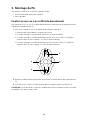
1 Following these guidelines, screw the mounting bracket to a wall or electrical box (NEMA
enclosure):
• The mounting bracket tabs should be pointing upward.
• If mounting to drywall, use the 4 screws and 4 wall anchors.
• If mounting to an EU electrical box (60.3mm), use 2 threaded screws and insert into the
holes marked “A” in the diagram shown below.
• If mounting to a US electrical box (83.3mm), use 2 threaded screws and insert into the
holes marked “B” in the diagram shown below
.
2 Connect the Ethernet cable (for power and network connection) to the LAN port on the back
of the AP.
3 To mount the AP onto the mounting bracket, insert the mounting-bracket tabs into the slots
on the back of the AP.
CAUTION: If you are mounting the AP on a wall, you cannot use the slots on the bottom narrow
edge of the device. Instead, you must use the slots on back of the AP.
A
B
A
B

6
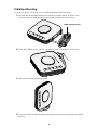
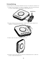
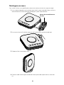
Tabletop Mounting
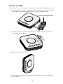
To install the AP on a flat surface such as a table or desktop, follow these steps:
1 Insert the tabs on the table stand into the slots on the side of the AP, as shown in the
illustration. Align the cable routing cut out toward the upper part of the stand.
2 To lock the stand to the AP, slide the stand back and the AP forward, as shown here:
3 Place the AP and table stand on the table.
4 Connect the Ethernet cable for power and network connection to the LAN port on the back
of the AP.
Cable routing cut out

7
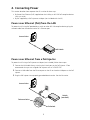
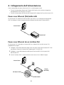
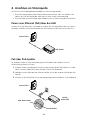
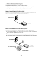
4. Connecting Power
This section describes how to power the AP in either of these ways:
• By Power Over Ethernet (PoE) supplied over the LAN by an 802.3af PoE compliant device
such as a switch.
• By PoE supplied by a PoE injector or midspan (not included with the AP).
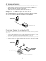
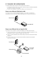
Power over Ethernet (PoE) from the LAN
To power the AP using PoE provided by a switch or other 802.3af compliant device, plug the
network cable from the device into the AP’s Ethernet port.
Power over Ethernet from a PoE Injector
To power the AP using a PoE injector or midspan (not included), follow these steps:
1 Connect the LAN cable from a switch to the Switch port on the PoE injector. 3Com
recommends that you use a Gigabit PoE injector such as 3CNJPSE-GIG
2 Connect a LAN cable from the Ethernet port on the AP to the other LAN port on the PoE
injector.
3 Plug the PoE injector into a properly grounded electric outlet. See the illustration.
PoE Switch
Access Point
Switch
(non-PoE)
Access Point
To Access Point
To Switch

8
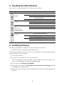
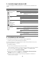
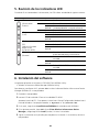
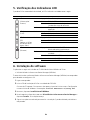
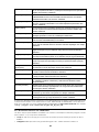
5. Checking the LED Indicators
When the AP is connected to power, LEDs indicate activity as follows:
6. Installing Software
The following application is included on the 3Com WIDMan Utility CD-ROM:
• Wireless Infrastructure Device Manager (WIDMan Utility)
To discover and configure the AP, you must first install the Wireless Infrastructure Device Manager
software (WIDMan) on your computer.
1 Turn on your computer.
2 Insert the 3Com Installation CD into the CD-ROM drive.
The CD menu appears. If it does not appear, start the Setup menu from the Windows Start
menu. For example: Start > Run > d:\autorun.exe
3 On the menu, click Install/Uninstall WIDMan.
4 On the next screen, double-click 3Com Wireless Infrastructure Device Manager and then
click Install. The installation begins.
5 Follow the instructions on each screen to complete the installation. If prompted, reboot the
computer.
Indicator Color State Description
LED 1
(Power/
System)
Off No power
Amber On Failure of CPU or system
Blinking System initiation or reset (software self-
testing and loading)
Green On Powered on and ready for operation
LED 2
(2.4G)
Green Off Radio disabled
On Radio enabled
Blinking Activity
LED 3
(5G)
(on the 3Com
AirConnect 9550
Access Point only)
Green Off Radio disabled
On Radio enabled
Blinking Activity
LED 4
(Ethernet)
Off No 10/100/1000 BASE-T link detected, or
administratively disabled
Amber On 10/100 BASE-T link detected; no activity
Blinking 10/100 BASE-T link activity
Green On 1000 BASE-T link detected; no activity
Blinking 1000 BASE-T link activity

9
7. Connecting to the AP
To connect to the AP, you must first determine the AP’s IP address in one of these ways.
Finding the IP Address on Networks with a DHCP Server
If your network has a DHCP server, it automatically assigns an IP address to the AP. The AP takes
between 1 and 2 minutes to detect a DHCP server on the network. Use WIDMan to locate the AP
on the network and view its IP address. See
“Using the WIDMan Utility”.
Finding the IP Address on Networks Without a DHCP Server
If your network does not have a DHCP server, the AP uses a default factory-assigned IP address
(169.254.2.111).
Using the WIDMan Utility
3Com WIDMan (Wireless Infrastructure Device Manager) software lets you discover and configure
your AP. Follow these steps to use WIDMan to determine the AP’s IP address.
1 Connect the AP to the network.
2 Launch WIDMan from the Windows Start menu: Start > Programs > 3Com Wireless >
Wireless Infrastructure Device Manager. The Wireless Network Tree screen displays your
AP when it is detected.
3 Click to select your AP, and then click Properties. Make a note of your AP’s IP address.
4 To access the AP’s web interface, select the AP and click Configure or double-click the AP.
8. Configuring the AP
To configure the AP after you determine its IP address, follows these steps:
1 Launch your computer’s web browser. In the address bar, enter your AP’s IP address and
press Enter.
2 At the AP Login Screen, type the user name and password, and then click Log On. The
default username and password are case-sensitive:
• Username: admin
• Password: password
3 If this is the first time that you are logging onto the AP, you are prompted to select the
country in which you will be using the device. Choose your country from the menu and then
click Apply.
4 To configure your AP, click Setup Wizard in the menu on the left side of the screen.
5 Follow the prompts on the screen. Use the Next and Back buttons to move through the
screens. Click Finish when you are done.
For details on using the Wireless Infrastructure Device Manager and configuring your AP, see the
3Com AirConnect 9550 11n 2.4+5GHz PoE Access Point / 3Com AirConnect 9150 11n 2.4GHz
PoE Access Point User Guide on our website:
http://www.3Com.com

10
9. Troubleshooting
For troubleshooting information please refer to your User's Guide or visit 3Com’s World Wide
Web site:
http://www.3Com.com.

Guide de mise en route
3Com
®
AirConnect
®
9550
Point d'accès PoE 11n 2,4+5 GHz
3CRWE955075 / WL-605
3Com
®
AirConnect
®
Point d'accès PoE 9150 11n 2,4 GHz
3CRWE915075 / WL-604
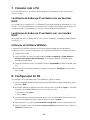
Le présent guide de mise en route indique la procédure à suivre pour installer et configurer le
point d'accès PoE 3Com AirConnect 9550 11n 2,4+5
GHz et le point d'accès PoE 3Com
AirConnect 9150 11n 2,4
GHz. Remarque :Ce guide se sert du terme PA (Point d'Accès) pour
désigner ces dispositifs.
Avant d'installer ou de déplacer le PA, veuillez lire attentivement les informations relatives à la
sécurité présentées dans la section
“Informations relatives à la sécurité”, à la page 13 du présent
guide.
Présentation de ce guide
Le présent guide décrit les étapes d'installation du PA. Il aborde les sujets suivants :
• Fonctions du PA
• Enregistrement du produit pour le service après vente
• Informations relatives à la sécurité
• 1: Déballage du PA
• 2: Préparation de l'installation
• 3: Montage du PA
• 4: Mise sous tension
• 5: Vérification des voyants lumineux
• 6: Installation du logiciel
• 7: Connexion au PA
• 8: Configuration du PA
• Dépannage

12
Fonctions du PA
Fonction Description
Port Ethernet Le port Ethernet offre une connexion Ethernet 10/100/1000 BASE-T à
un commutateur. Utilisez un câble droit de catégorie 5 et des
connecteurs RJ45 standard pour relier le PA au réseau.
Voyants Les voyants indiquent si le dispositif est sous tension et si des activités
sont en cours. Reportez-vous à la section
“Vérification des voyants
lumineux”, à la page 18 pour plus d'informations.
Connecteurs d'antenne Le PA dispose de trois antennes intégrées. En outre, trois connecteurs
d'antenne RSMA permettent de brancher des antennes externes
supplémentaires.
Bouton de
réinitialisation
Permet de rétablir les paramètres d'usine : à la mise sous tension,
maintenez le bouton de réinitialisation appuyé pendant plus de 5
secondes.
Port pour la console
RJ45
Ce port fournit une interface série au PA à des fins de diagnostic. Par
défaut : vitesse de 115,2K, 8 bits, pas de parité, 1 bit d'arrêt.
Attache de montage
mural et socle de
bureau
La combinaison attache et socle permet de fixer le dispositif au mur ou
sur une table.
Port Ethernet
Attache de montage mural/
Voyants
Port pour la console RJ45
Bouton de réinitialisation
Socle pour bureau
Encoches pour la
fixation au bureau
Encoches pour la
fixation au mur
Connecteurs pour les antennes en option

13
Enregistrement du produit pour le service après vente
Pour obtenir l'aide par téléphone dans le cadre de la garantie ainsi que d'autres avantages, vous
devez enregistrer votre produit à :
http://eSupport.3com.com/
Soutien technique et réparation par téléphone
3Com offre un accès aux services d'aide technique et de réparation par téléphone, courriel et
Internet. Pour accéder à ces services dans votre région, utilisez le numéro de téléphone, l'URL ou
l'adresse électronique corrects depuis l'URL suivante :
http://csoweb4.3com.com/contactus/
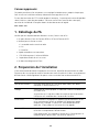
Informations relatives à la sécurité
Cet équipement doit être installé conformément aux normes de construction locales et nationales,
aux restrictions réglementaires et au règlement du FCC. Pour garantir la sécurité des personnes et
des équipements, seul le personnel chargé de la gestion du réseau est autorisé à procéder à
l'installation du PA.
Lisez attentivement les informations de sécurité suivantes avant d'installer ou de désinstaller le
dispositif.
AVERTISSEMENT : Ces avertissements contiennent des instructions que vous devez
impérativement suivre pour votre propre sécurité. Respectez strictement toutes les
instructions.
AVERTISSEMENT : Faites preuve de la plus grande attention lors des opérations
d'installation et de désinstallation de l'unité.
AVERTISSEMENT : Cette unité fonctionne en très basse tension, et respecte les
normes IEC
950 / IEC 60950 de la Commission électrotechnique internationale. Ces
normes sont respectées uniquement si l'équipement auquel elle est connectée
fonctionne également en très basse tension.
AVERTISSEMENT : L'unité ne contient ni fusibles, ni pièces nécessitant un entretien
particulier. Si vous rencontrez un problème que vous ne parvenez pas à résoudre en
suivant les mesures correctives proposées dans ce guide, contactez votre fournisseur.
AVERTISSEMENT : Ports RJ45. Il s'agit de sockets de données RJ45. Ces sockets ne
peuvent en aucun cas être utilisés comme prises de téléphone standard ou pour
connecter le dispositif à un autocommutateur privé classique ou un réseau
téléphonique public. Branchez uniquement des connecteurs de données RJ45, des
systèmes de téléphonie en réseau ou des téléphones en réseau à ces sockets.
Il est possible de brancher des câbles de données blindés ou non blindés équipés de
prises blindées ou non blindées à ces sockets de données.
AVERTISSEMENT : Conformément aux dispositions relatives à l'exposition aux
radiofréquences du règlement du FCC, il convient de se tenir à une distance minimale
de 20 cm de l'antenne lorsque le PA est en fonctionnement.

14
Canaux approuvés
Ce produit peut être utilisé uniquement sur une plage limitée de canaux, propre à chaque pays.
Pour assurer une installation correcte, sélectionnez votre pays dans la liste.
En vertu des restrictions du FCC et celles propres à votre pays, il se peut que les canaux disponibles
soient limités au niveau de votre produit. Si d'autres canaux sont autorisés dans votre pays,
consultez le site Web de 3Com pour obtenir la dernière version du logiciel :
www.3Com.com
1. Déballage du PA
Vérifiez que vous disposez bien des éléments suivants, fournis avec le PA :
• Un point d'accès 3Com AirConnect 9550 ou 3Com AirConnect 9150
• Matériel pour la fixation murale :
• 1 ensemble attache murale et socle
• 4 vis
• 4 chevilles
• 8 pieds autocollants en caoutchouc
• 1 CD-ROM contenant l'utilitaire WIDMan
• 1 copie de ce Guide de mise en route
• Un document de garantie 3Com
2. Préparation de l'installation
3Com recommande de mettre l'équipement sous tension, de vérifier le branchement du câble
Ethernet et de s'assurer que les voyants fonctionnent avant d'installer le PA dans un emplacement
difficile d'accès. Vérifiez également les points suivants avant de fixer ou de connecter le PA :
Fonction Description
Port du commutateur Pour relier votre réseau sans fil à votre réseau câblé, vous devez
connecter un commutateur au PA.
Câblage Vérifiez que le site est équipé d'un câble droit Ethernet standard avant
d'installer le PA.
Assurez-vous qu'il s'agit d'un câble très souple et que le connecteur
RJ45 passe sans encombre dans l'encoche de l'attache.
Alimentation L'alimentation est assurée par un appareil PoE de norme 802.3af tel
qu'un commutateur PoE ou un injecteur PoE (également appelé
midspan PoE). Exemple : 3CNJPSE-GIG. Pour des performances
optimales, 3Com préconise l'utilisation d'un lien gigabit.
Adresse MAC Notez l'adresse MAC du PA pour référence ultérieure avant d'installer
le PA dans un emplacement difficile d'accès.
Cette adresse MAC est imprimée à l'arrière du PA. Des étiquettes sur
lesquelles figure l'adresse MAC sont fournies avec le PA.

15
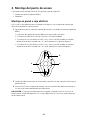
3. Montage du PA
Vous pouvez installer le PA sur plusieurs types de surface :
• Mur ou coffret de branchement normalisé
• Dessus de table
Fixation au mur ou à un coffret de branchement
Pour monter le PA sur un mur ou à coffret de branchement, servez-vous de l'attache fournie avec
le dispositif. Procédez comme suit :
1 Pour visser l'attache au mur ou au coffret de branchement normalisé :
• Les pattes de l'attache doivent se trouver vers le haut.
• En cas de montage sur cloison sèche, utilisez les 4 vis et les 4 chevilles.
• En cas de montage à un coffret de branchement EU (30,3 mm), utilisez 2 vis filetées et
insérez-les dans les trous marqués «
A » dans la figure ci-dessous.
• En cas de montage à un coffret de branchement US (83,3mm), utilisez 2 vis filetées et
insérez-les dans les trous marqués «
B » dans la figure ci-dessous..
2 Branchez le câble Ethernet (alimentation et connexion au réseau) dans le port LAN au dos du
PA.
3 Pour fixer le PA à l'attache, insérez les pattes dans les encoches figurant au dos du PA.
ATTENTION : En cas de fixation murale, vous ne devez pas utiliser les encoches situées sur le côté
du dispositif. mais celles situées au dos.
A
B
A
B

16
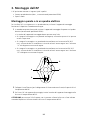
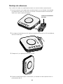
Fixation sur table
Pour installer le PA sur une surface plane, comme une table ou un bureau, procédez comme suit :
1 Insérez les pattes du socle dans les encoches situées sur le côté du PA, comme illustré dans la
figure. Alignez l'encoche de passage du câble vers la partie supérieure du socle.
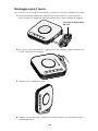
2 Pour fixer le socle au PA, faites glisser le socle vers l'arrière et le PA vers l'avant, comme
illustré dans la figure ci-dessous :
3 Placez le PA et le socle sur la table.
4 Branchez le câble Ethernet pour l'alimentation et la connexion au réseau dans le port LAN
situé au dos du PA.
Encoche de passage du câble

17
4. Mise sous tension
Cette section explique comment mettre le PA sous tension au moyen des méthodes suivantes :
• Par PoE (Power Over Ethernet) assuré via le réseau local par le biais d'un dispositif PoE
répondant à la norme 802.3af, tel qu'un commutateur.
• Par PoE assuré via un injecteur PoE ou midspan (non fourni avec le PA).
PoE (Power over Ethernet) via le réseau local
Pour alimenter le PA par le biais d'un commutateur ou autre dispositif répondant à la norme
802.3af, il suffit de brancher le câble réseau du dispositif au port Ethernet du PA.
Power over Ethernet via un injecteur PoE
Pour mettre sous tension le PA au moyen d'un injecteur PoE ou midspan (non fourni), procédez
comme suit :
1 Branchez le câble LAN d'un commutateur au port correspondant de l'injecteur PoE. 3Com
recommande l'utilisation d'un injecteur PoE gigabit tel que le 3CNJPSE-GIG.
2 Connectez un câble LAN entre le port Ethernet du PA et l'autre port LAN de l'injecteur PoE.
3 Branchez l'injecteur PoE à une prise de courant avec mise à la terre. Consultez l'illustration.
Commutateur PoE
Point d'accès
Commutateur
(non PoE)
Point d'accès
Vers le point d'accès
Vers le commutateur

18
5. Vérification des voyants lumineux
Lorsque le PA est sous tension, différents voyants s'allument pour indiquer les activités en cours,
répertoriées ci-dessous :
6. Installation du logiciel
L'application suivante figure dans le CD-ROM de l'utilitaire WIDMan de 3Com :
• Wireless Infrastructure Device Manager (Utilitaire WIDMan)
Pour être en mesure de détecter le PA, vous devez tout d'abord installer le logiciel Wireless
Infrastructure Device Manager (WIDMan) sur votre ordinateur.
1 Allumez votre ordinateur.
2 Insérez le CD-ROM d'installation 3Com dans le lecteur.
Le menu du CD-ROM apparaît. S'il n'apparaît pas, vous pouvez le lancer à partir du menu
Démarrer de Windows. Exemple : Démarrer> Exécuter > d:\autorun.exe
3 Dans le menu, cliquez sur Install/Uninstall WIDMan.
4 À l'écran suivant, double-cliquez sur 3Com Wireless Infrastructure Device Manager puis
cliquez sur Install. L'installation commence.
5 Suivez les instructions figurant sur chaque écran pour procéder à l'installation. Redémarrez
l'ordinateur si vous y êtes invité.
Indicateur Couleur État Description
Voyant 1
(Alimentation/
Système)
Éteint Pas d'alimentation
Ambre Allumé Défaillance de l'unité centrale ou du
système
Clignotant Initiation ou réinitialisation du système
(autotest du système et chargement)
Vert Allumé En marche et prêt à l'emploi
Voyant 2
(2.4G)
Vert Éteint Radio désactivée
Allumé Radio activée
Clignotant Activité
Voyant 3
(5G)
(uniquement sur le
point d'accès
3Com AirConnect
9550)
Vert Éteint Radio désactivée
Allumé Radio activée
Clignotant Activité
Voyant 4
(Ethernet)
Éteint Pas de lien 10/100/1000 BASE-T détecté ou
désactivation administrative
Ambre Allumé Lien 10/100 BASE-T détecté ; pas d'activité
Clignotant Activité au niveau du lien 10/100 BASE-T
Vert Allumé Lien 1000 BASE-T détecté ; pas d'activité
Clignotant Activité au niveau du lien 1000 BASE-T
La pagina si sta caricando...
La pagina si sta caricando...
La pagina si sta caricando...
La pagina si sta caricando...
La pagina si sta caricando...
La pagina si sta caricando...
La pagina si sta caricando...
La pagina si sta caricando...
La pagina si sta caricando...
La pagina si sta caricando...
La pagina si sta caricando...
La pagina si sta caricando...
La pagina si sta caricando...
La pagina si sta caricando...
La pagina si sta caricando...
La pagina si sta caricando...
La pagina si sta caricando...
La pagina si sta caricando...
La pagina si sta caricando...
La pagina si sta caricando...
La pagina si sta caricando...
La pagina si sta caricando...
La pagina si sta caricando...
La pagina si sta caricando...
La pagina si sta caricando...
La pagina si sta caricando...
La pagina si sta caricando...
La pagina si sta caricando...
La pagina si sta caricando...
La pagina si sta caricando...
La pagina si sta caricando...
La pagina si sta caricando...
La pagina si sta caricando...
La pagina si sta caricando...
La pagina si sta caricando...
La pagina si sta caricando...
La pagina si sta caricando...
La pagina si sta caricando...
La pagina si sta caricando...
La pagina si sta caricando...
La pagina si sta caricando...
La pagina si sta caricando...
La pagina si sta caricando...
La pagina si sta caricando...
La pagina si sta caricando...
La pagina si sta caricando...
La pagina si sta caricando...
La pagina si sta caricando...
-
 1
1
-
 2
2
-
 3
3
-
 4
4
-
 5
5
-
 6
6
-
 7
7
-
 8
8
-
 9
9
-
 10
10
-
 11
11
-
 12
12
-
 13
13
-
 14
14
-
 15
15
-
 16
16
-
 17
17
-
 18
18
-
 19
19
-
 20
20
-
 21
21
-
 22
22
-
 23
23
-
 24
24
-
 25
25
-
 26
26
-
 27
27
-
 28
28
-
 29
29
-
 30
30
-
 31
31
-
 32
32
-
 33
33
-
 34
34
-
 35
35
-
 36
36
-
 37
37
-
 38
38
-
 39
39
-
 40
40
-
 41
41
-
 42
42
-
 43
43
-
 44
44
-
 45
45
-
 46
46
-
 47
47
-
 48
48
-
 49
49
-
 50
50
-
 51
51
-
 52
52
-
 53
53
-
 54
54
-
 55
55
-
 56
56
-
 57
57
-
 58
58
-
 59
59
-
 60
60
-
 61
61
-
 62
62
-
 63
63
-
 64
64
-
 65
65
-
 66
66
-
 67
67
-
 68
68


3com Model WL-604 Manuale utente
- Tipo
- Manuale utente
- Questo manuale è adatto anche per
in altre lingue
- English: 3com Model WL-604 User manual
- français: 3com Model WL-604 Manuel utilisateur
- español: 3com Model WL-604 Manual de usuario
- Deutsch: 3com Model WL-604 Benutzerhandbuch
- português: 3com Model WL-604 Manual do usuário
Documenti correlati
-
3com AP9552 Hardware Installation Manual
-
-
-
-
-
-
Hewlett Packard Enterprise 3CRUSBN275 Manuale utente
-
-
3com 3CRWE675075-UK - 11 Mbps Wireless LAN Workgroup Bridge Manuale utente
-