Harman Compact Stagebox Manuale del proprietario
- Categoria
- Apparecchiature musicali supplementari
- Tipo
- Manuale del proprietario
Questo manuale è adatto anche per

Soundcraft Compact Stagebox User/Installation Guide Page 1
Compact Stagebox
User & Installation Guide
®

Soundcraft Compact Stagebox User/Installation GuidePage 2
© Harman International Industries Ltd. 2011
All rights reserved
Parts of the design of this product may be protected by worldwide patents.
Part No. BD10.947004 Rev2 May 12
E&OE May 2012
Soundcraft is a trading division of Harman International Industries Ltd. Information in this
manual is subject to change without notice and does not represent a commitment on the part
of the vendor. Soundcraft shall not be liable for any loss or damage whatsoever arising from the
use of information or any error contained in this manual.
No part of this manual may be reproduced, stored in a retrieval system, or transmitted, in any
form or by any means, electronic, electrical, mechanical, optical, chemical, including photo-
copying and recording, for any purpose without the express written permission of Soundcraft.
Harman International Industries Limited
Cranborne House, Cranborne Road, Potters Bar, Hertfordshire, EN6 3JN, UK
Tel: +44 (0)1707 665000
Fax: +44 (0)1707 660742
http://www.soundcraft.com
®
IMPORTANT
Please read this manual carefully before using your unit for the rst time.
Warning: Any modication or changes made to this device, unless explicitly approved by
Harman, will invalidate the authorisation of this device. Operation of an unauthorised
device is prohibited under Section 302 of the Communications act of 1934, as amended,
and Subpart 1 of Part 2 of Chapter 47 of the Code of Federal Regulations.
NOTE: This equipment has been tested and found to comply with the limits for a Class B digital
device, pursuant to Part 15 of the FCC Rules. These limits are designed to provide reasonable
protection against harmful interference in a residential installation. This
equipment generates, uses and can radiate radio frequency energy and, if not installed and
used in accordance with the instructions, may cause harmful interference to radio
communications. However, there is no guarantee that interference will not occur in a particular
installation. If this equipment does cause harmful interference to radio or television reception,
which can be determined by turning the equipment off and on, the user is encouraged to try to
correct the interference by one or more of the following measures:
* Reorient or relocate the receiving antenna
* Increase the separation between the equipment and the receiver
* Connect the equipment into an outlet on a circuit different from that to which the receiver is
connected.
* Consult the dealer or an experienced radio/TV technician for help
For further details contact
Harman International Industries Ltd, Cranborne House, Cranborne Road, Potters Bar, Hertfordshire EN6 3JN, UK
Telephone +44(0) 1707 665000 Fax +44 (0)1707 660742 email: [email protected]
This equipment complies with the EMC directive 2004/108/EC
and LVD 2006/95/EC
This product is approved to safety standards
IEC 60065:2001 (Seventh Edition) +A1:2005
EN60065:2002 +AMD1:2006 + A11:2008
UL60065-07
CAN/CSA C22.2 No60065.03 + AMD01:2006
And EMC standards
EN55103-1:2009
EN55103-2:2009

Soundcraft Compact Stagebox User/Installation Guide Page 3
Contents
INTRODUCTION ........................................................................... 4
SAFETY NOTICES ....................................................................................... 4
SAFETY SYMBOL GUIDE ............................................................................ 4
IMPORTANT SAFETY WARNINGS ................................................................. 5
WARNINGS ............................................................................................................6
ELECTROSTATIC DISCHARGE (ESD).........................................................................6
WORKING SAFELY WITH SOUND ................................................................. 7
WARRANTY ............................................................................................... 7
FEATURES ................................................................................................ 8
Available Modules .................................................................................................8
Expansion Slots ....................................................................................................8
DETAILS ................................................................................................... 9
Primary Power Supply ............................................................................................9
Module Function Overview .....................................................................................9
CONNECTING IT UP ................................................................................. 12
Compact Stagebox Connecting to Vi2-Vi6 Range Consoles ....................................12
Compact Stagebox Connecting to Vi1 and Si Range Consoles ...............................14
REPLACING I/O MODULES ...................................................................... 15
INSTALLING D21m I/O CARDS ................................................................ 16
REPLACING/CLEANING THE FAN AIR FILTER MAT ..................................... 16

Soundcraft Compact Stagebox User/Installation GuidePage 4
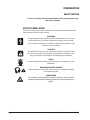
INTRODUCTION
SAFETY NOTICES
For your own safety and to avoid invalidation of the warranty please read
this section carefully.
SAFETY SYMBOL GUIDE
For your own safety and to avoid invalidation of the warranty all text marked with
these symbols should be read carefully.
WARNINGS
The lightning ash with arrowhead symbol is intended to alert the user
to the presence of un-insulated “dangerous voltage” within the prod-
uct’s enclosure that may be of sufcient magnitude to constitute a risk
of electric shock to persons.
CAUTIONS
The exclamation point within an equilateral triangle is intended to alert
the user to the presence of important operating and maintenance (ser-
vicing) instructions in the literature accompanying the appliance.
NOTES
Contain important information and useful tips on the operation of your
equipment.
HEADPHONES SAFETY WARNING
Contain important information and useful tips on headphone outputs
and monitoring levels.
ESD WARNING
The crossed-out hand symbol is intended to alert the user to devices
sensitive to electrostatic discharge. Please refer to the instructions on
page 5.

Soundcraft Compact Stagebox User/Installation Guide Page 5
IMPORTANT SAFETY WARNINGS
THIS UNIT MUST BE EARTHED!
Under no circumstances should the mains earth be disconnected from the mains lead.
The wires in the mains lead are coloured in accordance with the following code:
Earth: Green and Yellow (Green/Yellow - US)
Neutral: Blue (White - US)
Live: Brown (Black - US)
As the colours of the wires in the mains lead may not correspond with the coloured markings identifying
the terminals in your plug, proceed as follows:
• The wire which is coloured Green and Yellow must be connected to the terminal in the plug which is
marked with the letter E or by the earth symbol.
• The wire which is coloured Blue must be connected to the terminal in the plug which is marked with
the letter N.
• The wire which is coloured Brown must be connected to the terminal in the plug which is marked
with the letter L.
Ensure that these colour codings are followed carefully in the event of the plug being changed.
The internal power supply unit contains no user serviceable parts. Refer all servicing to a
qualied service engineer, through the appropriate Soundcraft dealer.
ELECTROSTATIC DISCHARGE (ESD)
Many semiconductor components are sensitive to electrostatic discharge (ESD). The lifespan of
assemblies contain ing such components can be drastically reduced by improper handling
during maintenance and repair. Please observe the following rules when handling ESD sensi-
tive components:
• ESD sensitive components should only be stored and transported in the packing material speci-
cally provided for this purpose.
• When performing a repair by replacing complete assemblies, the removed assembly must be sent
back to the supplier in the same packing material in which the replacement assembly was shipped.
If this should not be the case, any claim for a possible refund will be null and void.
• Unpacked ESD sensitive components should only be handled in ESD protected areas (EPA, e.g.
area for eld service, repair or service bench) and only be touched by persons wearing a wristlet
connected to the ground potential of the repair or service bench by a series resistor. The equipment
to be repaired or serviced as well as all tools and electrically semi-conducting work, storage, and
oor mats should also be connected to this ground potential.
• The terminals of ESD sensitive components must not come in uncontrolled contact with electro-
statically chargeable or metallic surfaces (voltage puncture, discharge shock hazard).
• To prevent the components from undened transient stress and possible damage due to inadmis-
sible voltages or compensation currents, electrical connections should only be established or sepa-
rated when the equipment is switched off and after any capacitor charges have decayed.

Soundcraft Compact Stagebox User/Installation GuidePage 6
WARNINGS
• Read these instructions.
• Keep these instructions.
• Heed all warnings.
• Follow all instructions.
• Clean the apparatus only with a dry cloth.
• Do not install near any heat sources such as radiators, heat resistors, stoves, or other apparatus
(including ampliers) that produce heat.
• Do not block any ventilation openings. Install in accordance with the manufacturer’s instructions.
• Do not use this apparatus near water.
• Do not defeat the safety purpose of the polarized or grounding type plug. A polarized plug has two
blades with one wider than the other. A grounding type plug has two blades and a third grounding
prong. The wide blade or the third prong are provided for your safety. When the provided plug does
not t into your outlet, consult an electrician for replacement of the obsolete outlet.
• Protect the power cord from being walked on or pinched particularly at plugs, convenience recepta-
cles and the point where they exit from the apparatus.
• Only use attachments/accessories specied by the manufacturer.
• Unplug this apparatus during lightning storms or when unused for long periods of time.
• Refer all servicing to qualied service personnel. Servicing is required when the appara-
tus has been damaged in any way such as power-supply cord or plug is damaged, liquid
has been spilled or objects have fallen into the apparatus, the apparatus has been
exposed to rain or moisture, does not operate normally or has been dropped.
• Use only with the cart, stand, tripod, bracket or table specied by the manufacturer, or
sold with the apparatus. When the cart is used, use caution when moving the cart/ap-
paratus combination to avoid injury from tip-over.
• No naked ame sources, such as lighted candles or cigarettes etc., should be placed on the appa-
ratus.
• Warning: To reduce the risk of re or electric shock, do not expose this apparatus to rain or moisture.
Do not expose the apparatus to dripping or splashing and do not place objects lled with liquids,
such as vases, on the apparatus.
• This unit contains no user serviceable parts. Refer all servicing to a qualied service engineer,
through the appropriate Soundcraft dealer.
• Ventilation should not be impeded by covering the ventilation openings with items such as newspa-
pers, table cloths, curtains etc.
• The disconnect device is the mains plug; it must remain accessible so as to be readily operable in
use.
• It is recommended that all maintenance and service on the product should be carried out by
Soundcraft or its authorised agents. Soundcraft cannot accept any liability whatsoever for any loss
or damage caused by service, maintenance or repair by unauthorised personnel.

Soundcraft Compact Stagebox User/Installation Guide Page 7
WORKING SAFELY WITH SOUND
Although your new unit will not make any noise until you feed it signals, it has the capability to produce
sounds which when monitored through a PA system or headphones can damage hearing over time.
The table below is taken from the Occupational Safety & Health Administration directive on Occupational
noise exposure (1926.52):
PERMISSIBLE NOISE EXPOSURE
DURATION PER DAY, HOURS SOUND LEVEL dBA SLOW RESPONSE
8 90
6 92
4 95
3 97
2 100
1.5 102
1 105
0.5 110
<0.25 115
Conforming to this directive will minimise the risk of hearing damage caused by long listening periods. A
simple rule to follow is the longer you listen the lower the average volume should be.
Please take care when working with your audio - if you are manipulating controls which you don’t under-
stand (which we all do when we are learning), make sure your monitors are turned down. Remember that
your ears are the most important tool of your trade, look after them, and they will look after you.
Most importantly - don’t be afraid to experiment to nd out how each parameter affects the sound - this
will extend your creativity and help you to get the best results.
Recommended headphone impedance is 50-600 ohms.
WARRANTY
1. Soundcraft is a trading division of Harman International Industries Ltd.
End User means the person who rst puts the equipment into regular operation.
Dealer means the person other than Soundcraft (if any) from whom the End User purchased the Equipment, provided
such a person is authorised for this purpose by Soundcraft or its accredited Distributor.
Equipment means the equipment supplied with this manual.
2. If within the period of twelve months from the date of delivery of the Equipment to the End User it shall prove defective
by reason only of faulty materials and/or workmanship to such an extent that the effectiveness and/or usability thereof
is materially affected the Equipment or the defective component should be returned to the Dealer or to Soundcraft and
subject to the following conditions the Dealer or Soundcraft will repair or replace the defective components. Any compo-
nents replaced will become the property of Soundcraft.
3. Any Equipment or component returned will be at the risk of the End User whilst in transit (both to and from the Dealer
or Soundcraft) and postage must be prepaid.
4. This warranty shall only be available if:
a) the Equipment has been properly installed in accordance with instructions contained in Soundcraft’s manual; and
b) the End User has notied Soundcraft or the Dealer within 14 days of the defect appearing; and
c) no persons other than authorised representatives of Soundcraft or the Dealer have effected any replacement of parts
maintenance adjustments or repairs to the Equipment; and
d) the End User has used the Equipment only for such purposes as Soundcraft recommends, with only such operating
supplies as meet Soundcraft’s specications and otherwise in all respects in accordance Soundcraft’s recommenda-
tions.
5. Defects arising as a result of the following are not covered by this Warranty: faulty or negligent handling, chemical or
electro-chemical or electrical inuences, accidental damage, Acts of God, neglect, deciency in electrical power, air-con-
ditioning or humidity control.
6. The benet of this Warranty may not be assigned by the End User.
7. End Users who are consumers should note their rights under this Warranty are in addition to and do not affect any other
rights to which they may be entitled against the seller of the Equipment.

Soundcraft Compact Stagebox User/Installation GuidePage 8
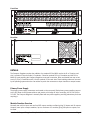
FEATURES
The Compact Stagebox is ideal for existing owners of Vi Series consoles as a cost-effective method of
expanding the input capability by expanding to up to 96 mic/line analogue inputs, or as a partner for the
Vi1 and Si range of consoles providing cost-effective remote I/O capability in conjunction with the optional
MADI interface cards available for those consoles.
The Soundcraft Compact Stagebox offers a high density of I/O connections in only 4U of rack space. The
modular unit is fully congurable but is offered with a standard conguration of 32 mic/line inputs, 8 line
outputs, 4 x 2 channels of AES/EBU outputs and 2 expansion slots for standard Studer D21m I/O cards.
The D21m is the I/O architecture for Studer as well as Soundcraft digital mixing systems and allows con-
nection to most popular digital formats, including CobraNet®, Aviom A-Net®16, EtherSound®, ADAT and
RockNet®. A MADI recording interface can also be tted to the expansion slots.
It is possible to equip the Compact Stagebox with an additional 16 mic/line input XLR module instead of
the output module, providing 48 inputs. In this case, analogue or AES outputs could still be obtained on
D-Type connectors via D21m cards tted to the expansion slots.
As well as the exibility of the D21m option card interface, the Compact Stagebox uses the same I/O
modules as found in the Soundcraft Vi1 console. As a result it is possible to move or share modules
between console and stagebox, should a different conguration of I/O be required on either the Vi1 or
the stagebox. For example, the 8 line out/AES output card from the stagebox could be tted to the Vi1
console in place of a 16-channel line output card. Alternatively, the mic input modules can be replaced by
output modules if large numbers of outputs are required.
When tting cards to the expansion slots it should be noted that the maximum input and output capacity
of the Compact Stagebox is limited by the MADI console link to 64 in/64 out.
The Compact Stagebox is connected to the host console using either Cat-5 or optical-bre MADI, the same
way as the larger 64 mic/line Vi6 Stagebox is hooked up, and shares the same redundant MADI cable
capability. The unit comes complete with twin redundant power supplies, thermostatically-controlled fan
cooling and full LED status monitoring. An eight-channel GPIO interface is provided as well.
Available Modules
• 16 x mic/line inputs (A947.043000SP)
• 16 x line outputs (A947.043500SP)
• 8 x line outputs + 4 x 2-ch AES/EBU outputs (A947.043700SP)
Expansion Slots
These may be used for one* or two of the following standard Studer D21m I/O cards:
• 8-channel line inputs (RS2425SP)
• 8-channel line outputs (RS2424SP)
• * 8 x 2-channel AES inputs and outputs (RS2422SP)
• 4-channel mic/line inputs with 4 x direct outputs (RS2423SP)
• * 64-channel MADI optical/multimode (RS2426SP) or Cat-5 (RS2409SP)
• 16-channel ADAT inputs and outputs (RS2360SP)
• * 16-channel TDIF inputs and outputs (RS2564SP)
• 16-channel Aviom A-Net® outputs (RS2497SP)
• 32-channel CobraNet® inputs and outputs (RS2485SP)
• *# 64-channel EtherSound® inputs and outputs
• *# 64-channel RockNet® inputs and outputs
• 16-channel SDI deembedder (RS2552SP)
• 16-channel Dolby® E decoder (RS2553SP)
# Available from 3
rd
party manufacturers or distributors only - please contact www.digigram.com for EtherSound® options,
www.riedel.net for RockNet® options.

Soundcraft Compact Stagebox User/Installation Guide Page 9
Front View
Rear View
DETAILS
The Compact Stagebox requires the addition of a standard D21m MADI card to the Vi or Si option card
slot. It contains 3 slots for audio I/O modules, 2 slots for optional D21m I/O modules and the D21m
MADI HD card providing the Compact Stagebox-to-console connection. Slots are labeled from top to bot-
tom A/C/E for I/O modules and K/L for the optional D21m card slots. These labeling references are used
by the patching system when the user wishes to patch the connectors to input channels or output busses.
Primary Power Supply
The primary power supply connectors are located on the rear panel. Both primary power supplies connect
to the IEC inlets via their power switches and provide a full range AC inlet, converting 100 to 240 V AC to
24 V DC. The Compact Stagebox is normally tted with two power supplies, providing redundancy for those
requiring it.
Module Function Overview
Normally two mic/line input and one line/AES output modules are tted, giving 32 inputs and 16 outputs.
However, more input or output modules, up to a maximum of 3 modules giving 48 inputs or outputs, can
be tted.

Soundcraft Compact Stagebox User/Installation GuidePage 10
Input Modules
Input modules handle 16 x mic/line amp, phantom power and A-to-D converter. An LED per input indi-
cates whether the phantom power is activated.
Output Modules
There are two different output module types available, both handling 16 outputs in total. In the standard
conguration, an output module with 8 x D-to-A converters and electronically balanced line outputs as
well as 8 AES/EBU output channels is tted. An all-analogue line output module with 16 electronically
balanced line outputs is optionally available. The modules have a set of relays which will mute the outputs
if the power fails.
LED Status Indicators
Status indicator LEDs are available for power rails, IO modules, fan and temperature alarm, and a RECON-
FIG button that must be pressed after the card conguration has been changed.
MADI HD Link Card
This card provides the audio and control connections to the console through either a Cat-5 or an Optical-
bre MADI link. The corresponding MADI card in the console transmits the clock for the Compact Stagebox
down the MADI stream. The second input on the card can either be used to provide a redundant connec-
tion to the console, or to connect to a second system if two consoles are used for a monitor/FOH congu-
ration.
The MADI card indicates its clock status with the ‘LOCK’ LED on the card. An RS422 link output is also
tted, allowing transmission of RS422 data via a ‘pipeline’ within the MADI stream from a corresponding
port on the console’s MADI card for remote RS422 control. (This feature is supported by Vi-Series con-
soles only).
For single cable operation: The front panel toggle switch must be set to either ‘MAIN’ or ‘AUX’,
depending on which socket is being used.
For dual cable (redundant) operation: The front panel toggle switch must be set to ‘RED’
mode.
Refer to the illustrations on the following pages.
Expansion Slots K and L (for optional D21m Cards)
In these slots one or two additional input or output cards may be installed (refer to page 8 for available
cards, page 16 for installation details). For more information on the D21m cards please refer to the ‘Vi
IO Option Cards Technical Information’ document available from www.soundcraft.com in the ‘Downloads’ -
‘User Guides’ - ‘Soundcraft Vi1’ area.

Soundcraft Compact Stagebox User/Installation Guide Page 11
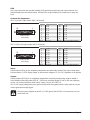
GPIO
Two D-type connectors are provided handling 8 GP (general purpose) input and output channels, con-
trolled remotely from the control surface. GP inputs are on opto-isolators, GP outputs are on relay con-
tacts.
Connector Pin Assignments:
GPI 1-8 (25-pin D-type, female, UNC 4-40 thread)
Pin Signal ‘GPI 1-8’ Pin Signal ‘GPI 1-8’
1 GPI 1a 14 GPI 1b
2 GPI 2a 15 GPI 2b
3 GPI 3a 16 GPI 3b
4 GPI 4a 17 GPI 4b
5 GPI 5a 18 GPI 5b
6 GPI 6a 19 GPI 6b
7 GPI 7a 20 GPI 7b
8 GPI 8a 21 GPI 8b
9-13 GND (0 V) 22-25 VCC (+5 V/600 mA max.)
GPO 1-8 (25-pin D-type, female, UNC 4-40 thread)
Pin Signal ‘GPO 1-8’ POn Signal ‘GPO 1-8’
1 GPO 1a 14 GPO 1b
2 GPO 2a 15 GPO 2b
3 GPO 3a 16 GPO 3b
4 GPO 4a 17 GPO 4b
5 GPO 5a 18 GPO 5b
6 GPO 6a 19 GPO 6b
7 GPO 7a 20 GPO 7b
8 GPO 8a 21 GPO 8b
9-13 GND (0 V) 22-25 VCC (+5 V/600 mA max.)
Inputs:
Control inputs (GPI Xa/b) are completely independent and electrically isolated. They may be used either
with the internal +5 V DC supply voltage, or with external voltages of 5...24 V DC, regardless of the polarity.
Outputs:
Control outputs (GPO Xa/b) are completely independent, electrically isolated relay contacts, closed if
active. Maximum switching power 62.5 VA / 30 W; max. switching voltage 50 V AC or DC; max. switching
current 1 A. Contact resistance (initial value) is max. 100 mΩ at 6 V DC/1 A.
The +5 V DC supply voltage and/or the ground (GND) terminals, together with the relay contacts, may be
used to generate an output signal.
The total current supplied by all VCC (+5 V DC) pins of the GPI/GPO 1-8 connectors must not
exceed 600 mA.
Solder/Crimp View
(or Socket View)
1
1425
13
Solder/Crimp View
(or Socket View)
1
1425
13

Soundcraft Compact Stagebox User/Installation GuidePage 12
CONNECTING IT UP
Compact Stagebox Connecting to Vi2-Vi6 Range Consoles
Note: Connections from the local rack to the Compact Stagebox may vary depending on actual ightcase
and breakout panel options.
Vi 2-6 Console
Console-to-Local Rack Cable

Soundcraft Compact Stagebox User/Installation Guide Page 13
Compact Stage Box
Console-to-Local Rack Cable
Optical or RJ45 Cables
depending on MADI card type
Local Rack

Soundcraft Compact Stagebox User/Installation GuidePage 14
Compact Stagebox Connecting to Vi1 and Si Range Consoles
• Connections from the console to the Compact Stagebox may vary depending on actual ightcase
and breakout panel options.
• For SI range consoles, currently only an optical multi-mode bre version MADI Card is available;
however, the application is similar to the example given below.
This switch must be set to MAIN or AUX (de-
pending on which connector is used) if using
one cable, and to RED if using 2 cables.
Compact Stage Box
Vi1 (or Si Range) Console
with optional MADI card in the extension slot.
Optical or RJ45 Cables
depending on MADI card type

Soundcraft Compact Stagebox User/Installation Guide Page 15
REPLACING I/O MODULES
In order to replace an input or output module - e.g. if more inputs or outputs are required
- rst switch the Compact Stagebox OFF and unplug the mains cable(s).
• Observe the precautions for handling devices sensitive to electrostatic discharge – refer to p. 5.
• For all screws in question a no. 2.5 Allen screwdriver is used.
• Remove the top cover of the Compact Stagebox (2 countersunk screws M4x8 on top, 13 screws
M4x6 around the upper edge).
• Then remove the module concerned. Unplug the at cable from the backplane PCB and the supply
loom from the module.
• Remove the 4 screws M4x6 at the module’s edges.
• Insert the new module and x it with the 4 screws. Connect the at cable to the corresponding
socket on the backplane PCB (for correct connection refer to the illustration below).
• Connect the supply loom to the module. Supply looms are identical for input and output modules,
no particular order has to be followed when reconnecting them. Like the power connections in a PC,
there is one connector more than modules to feed; the fourth connector is not used.
• For xing the top cover it is recommended to tighten all screws only after all of them have been
inserted a few turns into their threads.
• Connect the Compact Stagebox to the mains again, switch it on and press the RECONFIG button
with a small tool (e.g. the Allen screwdriver used before).
• Remember that the new input/output count needs to be congured in your console’s I/O mapping.
Please refer to its user guide.
Input Modules
TOP (A)
MIDDLE (C)
BOTTOM (E)
Output Modules
TOP (A)
MIDDLE (C)
BOTTOM (E)
The 3 module slots are labeled A, C and E; they correspond to the connectors of the backplane PCB ac-
cording to the illustration above. There are 3 connectors on the left for input modules, and 3 on the right
for output modules. Modules must be connected to the correct connector in order to have a correct as-
signment of input and/or output channels.
In the standard conguration (2 input modules in slots A and C, and 1 output module in slot E) the mod-
ules are connected as follows:
Input module A è top connector on the left side of the backplane (P2)
Input module C è middle connector on the left side of the backplane (P13)
Output module E è bottom connector on the right side of the backplane (P20).

Soundcraft Compact Stagebox User/Installation GuidePage 16
If someone wanted now that all 3 modules are inputs to give a 48 input/0 output stagebox, they are con-
nected as follows:
Input module A è top connector on the left side of the backplane (P2)
Input module C è middle connector on the left side of the backplane (P13)
Added input module E è bottom connector on the left side of the backplane (P19).
Supply looms are identical for input and output modules. No particular order has to be followed when re-
connecting them. Like the power connections in a PC, there is one connector more than modules to feed;
this connector is not used.
INSTALLING D21m I/O CARDS
• In the K and L slots, one or two additional D21m input or output cards may be installed.
• In order to do so, rst switch the Compact Stagebox OFF and unplug the mains cable(s).
• Remove the blank panel(s) with a size 2 screwdriver and insert the D21m card(s). Re-tighten their
screws.
• Connect the Compact Stagebox to the mains again, switch it on and press the RECONFIG button
with a small tool (e.g. a size 2.5 Allen screwdriver).
• Remember that the new input/output count needs to be congured in your console’s I/O mapping.
Please refer to its user guide.
For more information on the D21m cards please refer to the ‘Vi IO Option Cards Technical Information’
document available from www.soundcraft.com in the ‘Downloads’ - ‘User Guides’ - ‘Soundcraft Vi1’ area.
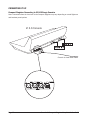
REPLACING/CLEANING THE FAN AIR FILTER MAT
• For cleaning or replacing the air lter mat, just pull the black frame away from the fan air inlet and
remove the lter mat.
• In order to clean the lter mat, thoroughly rinse it with warm water and let it dry completely before
reinstalling it.
-
 1
1
-
 2
2
-
 3
3
-
 4
4
-
 5
5
-
 6
6
-
 7
7
-
 8
8
-
 9
9
-
 10
10
-
 11
11
-
 12
12
-
 13
13
-
 14
14
-
 15
15
-
 16
16


Harman Compact Stagebox Manuale del proprietario
- Categoria
- Apparecchiature musicali supplementari
- Tipo
- Manuale del proprietario
- Questo manuale è adatto anche per
in altre lingue
Altri documenti
-
Omron S8V-CP Manuale utente
-
SoundCraft SPIRIT F1 Manuale del proprietario
-
-
-
Behringer Wing Guida Rapida
-
-
-
AJA FS4 Installation and Operation Guide
-
Yamaha PM5000 Manuale del proprietario
-
SoundCraft GB2R Manuale del proprietario