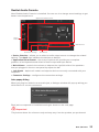
MSI 7D03 Manuale del proprietario
- Categoria
- Schede madri
- Tipo
- Manuale del proprietario
Questo manuale è adatto anche per

1
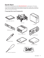
Quick Start
Quick Start
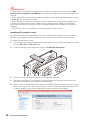
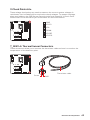
Thank you for purchasing the MSI® MEG Z590 GODLIKE motherboard. This Quick
Start section provides demonstration diagrams about how to install your computer.
Some of the installations also provide video demonstrations. Please link to the URL to
watch it with the web browser on your phone or tablet. You may have even link to the
URL by scanning the QR code.
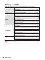
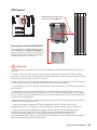
Preparing Tools and Components
Intel® LGA 1200 CPU
CPU Fan
DDR4 Memory
Graphics Card
SATA Hard Disk Drive
SATA DVD Drive
Phillips Screwdriver
Chassis
Power Supply Unit
A Package of Screws
Thermal Paste

2
Quick Start
Safety Information
∙ The components included in this package are prone to damage from electrostatic
discharge (ESD). Please adhere to the following instructions to ensure successful
computer assembly.
∙ Ensure that all components are securely connected. Loose connections may cause
the computer to not recognize a component or fail to start.
∙ Hold the motherboard by the edges to avoid touching sensitive components.
∙ It is recommended to wear an electrostatic discharge (ESD) wrist strap when
handling the motherboard to prevent electrostatic damage. If an ESD wrist strap is
not available, discharge yourself of static electricity by touching another metal object
before handling the motherboard.
∙ Store the motherboard in an electrostatic shielding container or on an anti-static
pad whenever the motherboard is not installed.
∙ Before turning on the computer, ensure that there are no loose screws or metal
components on the motherboard or anywhere within the computer case.
∙ Do not boot the computer before installation is completed. This could cause
permanent damage to the components as well as injury to the user.
∙ If you need help during any installation step, please consult a certified computer
technician.
∙ Always turn off the power supply and unplug the power cord from the power outlet
before installing or removing any computer component.
∙ Keep this user guide for future reference.
∙ Keep this motherboard away from humidity.
∙ Make sure that your electrical outlet provides the same voltage as is indicated on
the PSU, before connecting the PSU to the electrical outlet.
∙ Place the power cord such a way that people can not step on it. Do not place
anything over the power cord.
∙ All cautions and warnings on the motherboard should be noted.
∙ If any of the following situations arises, get the motherboard checked by service
personnel:
▪ Liquid has penetrated into the computer.
▪ The motherboard has been exposed to moisture.
▪ The motherboard does not work well or you can not get it work according to user
guide.
▪ The motherboard has been dropped and damaged.
▪ The motherboard has obvious sign of breakage.
∙ Do not leave this motherboard in an environment above 60°C (140°F), it may damage
the motherboard.

3
Quick Start
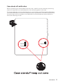
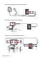
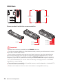
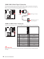
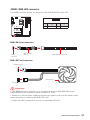
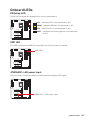
Case stand-off notification
Before installing the motherboard into the case, install first the necessary mounting
stand-off required for a motherboard on the mounting plate in the case.
To prevent damage to the motherboard, any unnecessary mounting stand-off between
the motherboard circuits and the computer case is prohibited. The Case standoff keep
out zone signs will be marked on the backside of motherboard (as shown below) to
serve as a warning to user.

4
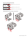
Quick Start
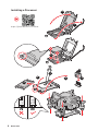
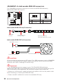
Installing a Processor
⚽
https://youtu.be/4ce91YC3Oww
1
2
3
6
4
5
7
8
9

5
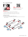
Quick Start
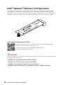
Installing DDR4 memory
http://youtu.be/T03aDrJPyQs
⚽
DIMMA2 DIMMA2
DIMMB2
DIMMA1
DIMMA2
DIMMB1
DIMMB2

6
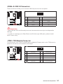
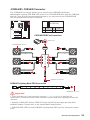
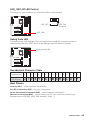
Quick Start
HDD LED
RESET SW
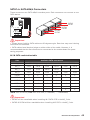
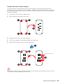
Connecting the Front Panel Header
http://youtu.be/DPELIdVNZUI
JFP1
HDD LED
HDD LED -
HDD LED +
POWER LED -
POWER LED +
POWER LED
1
2 10
9
+
+
+-
--
-
+
Power LED
HDD LED Reset Switch
Reserved
Power Switch
JFP1
1 HDD LED + 2 Power LED +
3 HDD LED - 4 Power LED -
5 Reset Switch 6 Power Switch
7 Reset Switch 8 Power Switch
9 Reserved 10 No Pin
RESET SW
POWER SW
POWER LED+
POWER LED-
HDD LED
⚽

7
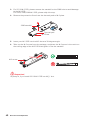
Quick Start
8 8
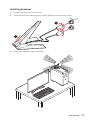
Installing the Motherboard
1
2
https://youtu.be/wWI6Qt51Wnc
⚽
Torque:
3 kgf·cm*
*3 kgf·cm
= 0.3 N·m
= 2.6 lbf·in

8
Quick Start
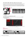
Connecting the Power Connectors
http://youtu.be/gkDYyR_83I4
⚽
PCIE_PWR1
CPU_PWR1
ATX_PWR1
CPU_PWR2

9
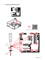
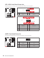
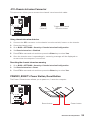
Quick Start
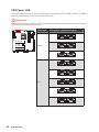
Installing SATA Drives
http://youtu.be/RZsMpqxythc
1
2
3
4
5
⚽

10
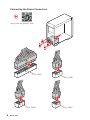
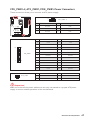
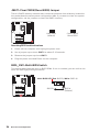
Quick Start
1
Installing a Graphics Card
http://youtu.be/mG0GZpr9w_A
2
3
4
5
6
⚽

11
Quick Start
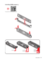
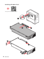
Full armor kit
or
M3 #6-32UNC

12
Quick Start
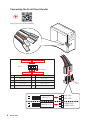
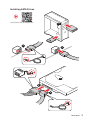
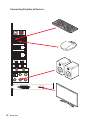
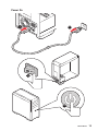
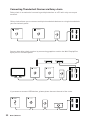
Connecting Peripheral Devices

13
Quick Start
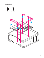
Power On
4
3
1
2

14
Contents
Contents
Quick Start ............................................................................................................. 1
Preparing Tools and Components.......................................................................... 1
Safety Information .................................................................................................. 2
Case stand-off notification ..................................................................................... 3
Installing a Processor ............................................................................................ 4
Installing DDR4 memory ........................................................................................ 5
Connecting the Front Panel Header ...................................................................... 6
Installing the Motherboard ..................................................................................... 7
Connecting the Power Connectors ........................................................................ 8
Installing SATA Drives ............................................................................................ 9
Installing a Graphics Card .................................................................................... 10
Full armor kit ........................................................................................................ 11
Connecting Peripheral Devices ............................................................................ 12
Power On .............................................................................................................. 13
Specifications ....................................................................................................... 17
JCORSAIR1 Connector Specification .................................................................... 25
Package contents ................................................................................................ 26
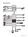
Block Diagram .................................................................................................... 27
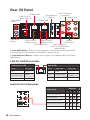
Rear I/O Panel ..................................................................................................... 28
LAN Port LED Status Table .................................................................................. 28
Audio Ports Configuration .................................................................................... 28
Realtek Audio Console ......................................................................................... 29
Installing Antennas ............................................................................................... 31
Connecting Thunderbolt Devices via Daisy-chain................................................ 32
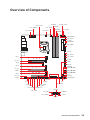
Overview of Components .................................................................................... 33
CPU Socket ........................................................................................................... 35
DIMM Slots ............................................................................................................ 36
PCI_E1~3: PCIe Expansion Slots .......................................................................... 37
M2_1~4: M.2 Slots (Key M) ................................................................................... 39
Installing M.2 XPANDER-Z Gen4 S card .............................................................. 42
SATA1~6: SATA 6Gb/s Connectors ....................................................................... 45
JFP1, JFP2: Front Panel Connectors ................................................................... 46
JAUD1: Front Audio Connector ............................................................................ 46
CPU_PWR1~2, ATX_PWR1, PCIE_PWR1: Power Connectors ............................. 47
JSLOW1: Slow Mode Booting Jumper .................................................................. 48
JLN1~2: Low Temperature Booting Jumper ....................................................... 48
W_FLOW1: Water Flow Meter Connector ............................................................ 48

15
Contents
V-Check Points Lite .............................................................................................. 49
T_SEN1~2: Thermal Sensor Connectors ............................................................. 49
JUSB1: USB 3.2 Gen 2 Type-C Connector ............................................................ 50
JUSB2~3: USB 3.2 Gen 1 Connector .................................................................... 50
JUSB4~5: USB 2.0 Connectors ............................................................................. 51
JTPM1: TPM Module Connector ........................................................................... 51
JDASH1 : Tuning Controller connector ................................................................ 52
CPU_FAN1, PUMP_FAN1, SYS_FAN1~8: Fan Connectors .................................. 54
JCI1: Chassis Intrusion Connector ....................................................................... 55
POWER1, RESET1: Power Button, Reset Button ................................................. 55
JBAT1: Clear CMOS (Reset BIOS) Jumper ........................................................... 56
BIOS_SW1: Multi-BIOS Switch ............................................................................. 56
JRGB1: RGB LED connector ................................................................................. 57
JRAINBOW1~2: Addressable RGB LED connectors ............................................ 58
JCORSAIR1: CORSAIR Connector ........................................................................ 59
DYNAMIC DASHBOARD II ..................................................................................... 60
DYNAMIC DASHBOARD II Status Table ................................................................ 60
Onboard LEDs ...................................................................................................... 61
EZ Debug LED ....................................................................................................... 61
XMP LED .............................................................................................................. 61
JPWRLED1: LED power input ............................................................................... 61
CPU Power LED ................................................................................................... 62
LED_SW1: EZ LED Control ................................................................................... 63
Debug Code LED ................................................................................................... 63
Hexadecimal Character Table .............................................................................. 63
Boot Phases .......................................................................................................... 63
Debug Code LED Table ......................................................................................... 64
ACPI States Codes ................................................................................................ 68
CPU core /CPU socket / System / MOS / PCH Temperature ............................... 68
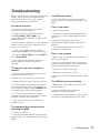
Installing OS, Drivers & MSI Center .................................................................... 69
Installing Windows® 10 ......................................................................................... 69
Installing Drivers .................................................................................................. 69
MSI Center ............................................................................................................ 69
UEFI BIOS ............................................................................................................. 70
BIOS Setup ............................................................................................................ 71
Entering BIOS Setup ............................................................................................. 71
BIOS User Guide ................................................................................................... 71
Resetting BIOS ...................................................................................................... 72
Updating BIOS ....................................................................................................... 72

16
Contents
Nahimic 3 ............................................................................................................. 74
Installation and Update ........................................................................................ 74
Audio Tab .............................................................................................................. 74
Microphone Tab .................................................................................................... 75
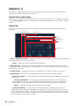
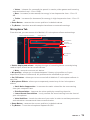
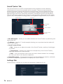
Sound Tracker Tab ............................................................................................... 76
Settings Tab .......................................................................................................... 76
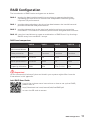
RAID Configuration .............................................................................................. 77
Intel® Optane™ Memory Configuration .............................................................. 78
Troubleshooting ................................................................................................. 79

17
Specifications
Specifications
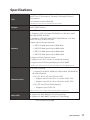
CPU
∙ Supports 10th Gen Intel® Core™ Processors, 11th Gen
Intel® Core™ Processors, Pentium® Gold and Celeron®
Processors*
∙ Processor socket LGA1200
* Please go to intel.com for compatibility information
Chipset Intel® Z590 Chipset
Memory
∙ 4x DDR4 memory slots, support up to 128GB*
∙ Supports 1R 2133/ 2666/ 2933 MHz for 10th Gen Intel®
CPU (by JEDEC & POR)*
∙ Supports 1R 2133/ 2666/ 2933/ 3200 MHz for 11th Gen
Intel® CPU (by JEDEC & POR)*
∙ Max. overclocking frequency:
▪ 1DPC 1R Max speed up to 5600 MHz
▪ 1DPC 2R Max speed up to 4800+ MHz
▪ 2DPC 1R Max speed up to 4400+ MHz
▪ 2DPC 2R Max speed up to 4000+ MHz
∙ Supports Dual-Channel mode
∙ Supports non-ECC mode, un-buffered memory
∙ Supports Intel® Extreme Memory Profile (XMP)
* Please refer www.msi.com for more information on compatible memory.
Expansion Slot
∙ 3x PCIe x16 slots
▪ Support x16/x0/x4, x8/x8/x4, x8/x4+x4/x4, x8+x8/x0/x4,
x8+(x4+x4)/x0/x4
▪ PCI_E1 & PCI_E2 slots (From CPU)
▫ Support up to PCIe 4.0 for 11th Gen Intel® CPU
▫ Support up to PCIe 3.0 for 10th Gen Intel® CPU
▪ PCI_E3 slot (From Z590 chipset)*
▫ Supports up to PCIe 3.0
* PCI_E3 will run at x1 speed when installing device in M2_4 slot.
Multi-GPU
∙ Supports 2-Way NVIDIA® SLI™ Technology
∙ Supports 3-Way AMD® CrossFire™ Technology
Continued on next page

18
Specifications
Continued from previous page
Thunderbolt 4
Intel® JHL8540 Thunderbolt™ 4 Controller
∙ 2x Thunderbolt™ 4 (Type-C) ports on the back panel
▪ Support up to 40 Gbps transfer rate with Thunderbolt
devices
▪ Support up to 20 Gbps transfer rate with USB4 devices
▪ Support up to 10Gbps transfer rate with USB 3.2
devices
▪ Support up to 5V/3A , 15W power charging
▪ Each port can daisy-chain up to three Thunderbolt 4
devices or five Thunderbolt 3 devices
▪ Supports up to 8K display (need to connect the
DisplayPort of the motherboard or discrete graphics card
to the Mini DisplayPort Input port on the back panel)
Storage
∙ 6x SATA 6Gb/s ports (from Z590 chipset)
∙ 4x M.2 slots (Key M)
▪ M2_1 (from CPU)
▫ Available only on 11th Gen Intel® CPU
▫ Supports up to PCIe 4.0 x4
▫ Supports 2242/ 2260/ 2280/ 22110 storage devices
▪ M2_2*, M2_3** & M2_4 slots (from Z590 chipset)
▫ M2_2 supports up to PCIe 3.0 x4 and SATA 6Gb/s,
2242/ 2260/ 2280 storage devices
▫ M2_3 supports up to PCIe 3.0 x4 and SATA 6Gb/s,
2242/ 2260/ 2280/ 22110 storage devices
▫ M2_4 supports up to PCIe 3.0 x4, 2242/ 2260/ 2280
storage devices***
▫ Intel® Optane™ Memory Ready****
∙ Supports Intel® Smart Response Technology for Intel
Core™ processors
* SATA2 will be unavailable when installing M.2 SATA SSD in the M2_2 slot.
** SATA5 & SATA6 will be unavailable when installing M.2 SSD in the M2_3 slot.
*** M2_4 will run at x2 speed when installing device in PCI_E3 slot.
**** Before using Intel® Optane™ memory modules, please ensure that you have
updated the drivers and BIOS to the latest version from MSI website.
Continued on next page

19
Specifications
Continued from previous page
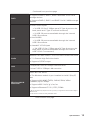
RAID
∙ Supports RAID 0, RAID 1, RAID 5 and RAID 10 for SATA
storage devices
∙ Supports RAID 0, RAID 1 and RAID 5 for M.2 NVMe storage
devices
USB
∙ Intel® Z590 Chipset
▪ 3x USB 3.2 Gen 2 10Gbps ports (2 Type-A ports on the
back panel and 1 Type-C internal connector)
▪ 2x USB 2.0 ports are available through the internal
USB 2.0 connector
∙ Hub GL850G
▪ 2x USB 2.0 ports are available through the internal
USB 2.0 connector
∙ Asmedia® 1074 Chipset
▪ 10x USB 3.2 Gen 1 5Gbps ports (6 Type-A ports on the
back panel, 4 ports are available through the internal
USB 3.2 Gen 1 connectors)
Audio
Realtek® ALC4082 Codec + ESS ES9218PQ Combo DAC/HPA
∙ 7.1-Channel High Definition Audio
∙ Supports S/PDIF output
LAN
1x Aquantia® AQC107 10Gbps LAN controller
1x Intel® I225-V 2.5Gbps LAN controller
Wireless LAN &
Bluetooth®
Intel® WiFi-6E AX210
∙ The Wireless module is pre-installed in the M.2 (Key-E)
slot
∙ Supports MU-MIMO TX/RX, 2.4GHz/ 5GHz/ 6GHz*
(160MHz) up to 2.4Gbps
∙ Supports 802.11a/ b/ g/ n/ ac/ ax
∙ Supports Bluetooth® 5.2**, FIPS, FISMA
* Wi-Fi 6E 6GHz may depend on every country’s regulations and will be ready in
WIN10 21H1.
** Bluetooth 5.2 will be ready in WIN10 21H1.
Continued on next page

20
Specifications
Continued from previous page
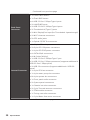
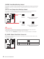
Back Panel
Connector
∙ 1x Clear CMOS button
∙ 1x Flash BIOS button
∙ 6x USB 3.2 Gen 1 5Gbps Type-A ports
∙ 2x LAN (RJ45) ports
∙ 2x USB 3.2 Gen 2 10Gbps Type-A ports
∙ 2x Thunderbolt 4 (Type-C) ports
∙ 2x Mini DisplayPort Input (for Thunderbolt 4 passthrough)
∙ 2x Wi-Fi Antenna connectors
∙ 5x OFC audio jacks
∙ 1x Optical S/PDIF Out connector
Internal Connector
∙ 1x 24-pin ATX main power connector
∙ 2x 8-pin ATX 12V power connectors
∙ 1x 6-pin ATX PCIE power connector
∙ 6x SATA 6Gb/s connectors
∙ 4x M.2 slots (M-Key)
∙ 1x USB 3.2 Gen 2 10Gbps Type-C port
∙ 2x USB 3.2 Gen 1 5Gbps connectors (supports additional 4
USB 3.2 Gen 1 5Gbps ports)
∙ 2x USB 2.0 connectors (supports additional 4 USB 2.0
ports)
∙ 1x 4-pin CPU fan connector
∙ 1x 4-pin water-pump fan connector
∙ 8x 4-pin system fan connectors
∙ 1x Front panel audio connector
∙ 2x System panel connectors
∙ 1x Chassis intrusion connector
∙ 2x 2-pin Thermal sensors connectors
∙ 1x TPM module connector
∙ 1x Tuning controller connector
∙ 1x 3-pin Water flow meter connector
Continued on next page
La pagina sta caricando ...
La pagina sta caricando ...
La pagina sta caricando ...
La pagina sta caricando ...
La pagina sta caricando ...
La pagina sta caricando ...
La pagina sta caricando ...
La pagina sta caricando ...
La pagina sta caricando ...
La pagina sta caricando ...
La pagina sta caricando ...
La pagina sta caricando ...
La pagina sta caricando ...
La pagina sta caricando ...
La pagina sta caricando ...
La pagina sta caricando ...
La pagina sta caricando ...
La pagina sta caricando ...
La pagina sta caricando ...
La pagina sta caricando ...
La pagina sta caricando ...
La pagina sta caricando ...
La pagina sta caricando ...
La pagina sta caricando ...
La pagina sta caricando ...
La pagina sta caricando ...
La pagina sta caricando ...
La pagina sta caricando ...
La pagina sta caricando ...
La pagina sta caricando ...
La pagina sta caricando ...
La pagina sta caricando ...
La pagina sta caricando ...
La pagina sta caricando ...
La pagina sta caricando ...
La pagina sta caricando ...
La pagina sta caricando ...
La pagina sta caricando ...
La pagina sta caricando ...
La pagina sta caricando ...
La pagina sta caricando ...
La pagina sta caricando ...
La pagina sta caricando ...
La pagina sta caricando ...
La pagina sta caricando ...
La pagina sta caricando ...
La pagina sta caricando ...
La pagina sta caricando ...
La pagina sta caricando ...
La pagina sta caricando ...
La pagina sta caricando ...
La pagina sta caricando ...
La pagina sta caricando ...
La pagina sta caricando ...
La pagina sta caricando ...
La pagina sta caricando ...
La pagina sta caricando ...
La pagina sta caricando ...
La pagina sta caricando ...
La pagina sta caricando ...
La pagina sta caricando ...
La pagina sta caricando ...
La pagina sta caricando ...
La pagina sta caricando ...
-
 1
1
-
 2
2
-
 3
3
-
 4
4
-
 5
5
-
 6
6
-
 7
7
-
 8
8
-
 9
9
-
 10
10
-
 11
11
-
 12
12
-
 13
13
-
 14
14
-
 15
15
-
 16
16
-
 17
17
-
 18
18
-
 19
19
-
 20
20
-
 21
21
-
 22
22
-
 23
23
-
 24
24
-
 25
25
-
 26
26
-
 27
27
-
 28
28
-
 29
29
-
 30
30
-
 31
31
-
 32
32
-
 33
33
-
 34
34
-
 35
35
-
 36
36
-
 37
37
-
 38
38
-
 39
39
-
 40
40
-
 41
41
-
 42
42
-
 43
43
-
 44
44
-
 45
45
-
 46
46
-
 47
47
-
 48
48
-
 49
49
-
 50
50
-
 51
51
-
 52
52
-
 53
53
-
 54
54
-
 55
55
-
 56
56
-
 57
57
-
 58
58
-
 59
59
-
 60
60
-
 61
61
-
 62
62
-
 63
63
-
 64
64
-
 65
65
-
 66
66
-
 67
67
-
 68
68
-
 69
69
-
 70
70
-
 71
71
-
 72
72
-
 73
73
-
 74
74
-
 75
75
-
 76
76
-
 77
77
-
 78
78
-
 79
79
-
 80
80
-
 81
81
-
 82
82
-
 83
83
-
 84
84


MSI 7D03 Manuale del proprietario
- Categoria
- Schede madri
- Tipo
- Manuale del proprietario
- Questo manuale è adatto anche per
in altre lingue
- English: MSI 7D03 Owner's manual
Documenti correlati
-
MSI MPG Z490M GAMING EDGE WIFI Manuale del proprietario
-
MSI MPG Z490 GAMING EDGE WIFI Manuale del proprietario
-
MSI MEG Z590 ACE Manuale del proprietario
-
MSI 7C71 Manuale utente
-
MSI MS-7C75 1.0 Manuale del proprietario
-
-
-
-
MSI MPG Z490 GAMING CARBON WIFI Manuale del proprietario
-
Altri documenti
-
Gamdias KRATOS E1-500 Manuale utente
-
Buffalo SSD-WA1.0T Manuale utente
-
Corsair CO-9050092-WW Manuale utente
-
Cable Matters 201034 Manuale utente
-
Peavey MA Series Module GEN- Manuale del proprietario
-
Corsair 32QHD240 Manuale utente
-
Corsair EX100U Manuale utente
-
Corsair XG5 Guida utente
-
Elgato Light Strip RGB LED 2000 Lumens Guida utente
-
Asus ROG Balteus QI Guida Rapida