Rockford Fosgate Prime R152 Installation & Operation Manual
- Categoria
- Altoparlanti per auto
- Tipo
- Installation & Operation Manual
Questo manuale è adatto anche per

I
E:
TM
Full
Range
Speakers
Serial
Number:
------
5.25"
-
R1
52
6.5"
-
R1653
6"x
9"
-R1693
Installation
&
Operation
Installation
et
fonctionnement
Instalaci6n
y
funcionamiento
Einbau
und
Betrieb
Installazione
e
funzionamento
Date
of
Purchase:
------

SAFETY
Before installatipn,
disconnect
the
battery
negative (-) terminal
to
prevent
damage
to
the
unit, fire
and/or
possible injury.
CARTON CONTENTS
(I)
Set Prime Series
Full
Range Speakers
(I)
Set of decorative trim rings
Mounting Hardware
INSTALLATION CONSIDERATIONS
Before beginning
any
installation, follow these simple rules:
I.
Be
sure
to
carefully read and understand
the
instructions before attempting
to
install these speakers.
2.
For safety, disconnect the negative lead from
the
battery prior
to
beginning
the
installation.
3.
For easier assembly, we suggest you run
all
wires prior
to
mounting your speakers
in
place.
4.
Use
high
quality connectors for a reliable installation and
to
minimize
signal
or
power loss.
5.
Think
before
you
drill!
Be
careful
not
to
cut
or
drill into gas tanks,
fuel
lines,
brake
or
hydraulic lines, vacuum lines
or
electrical wiring when working
on
any
vehicle.
If
installation
in
a boat, take care
not
to
cut
or
drill
through
the
main
hull.
6.
Never run wires underneath
the
vehicle. Running
the
wires inside
the
vehicle
or
hull
area provides tt)e
best
protection.
7.
Avoid running wires
over
or
through sharp edges. Use rubber
or
plastic
grommets
to
protect
any wires routed through metal, especially
the
firewall.
MOUNTING
I.
Determine where
the
speakers
will
be
mounted. Ensure
an
area large enough for
the
speaker
to
mount
evenly.
Be
sure
that
the
mounting location
is
deep enough
for
the
speaker
to
fit:
if
mounting
in
a door,
operate
all
functions (windows. locks,
etc.) through their entire operating range
to
ensure there
is
no obstruction.
2.
Refer
to
the specification
chart
to
determine
the
proper
diameter hole
to
cut
for
your speaker model.The template provided also gives the
proper
cutout
size.
3.
Using
the
template provided, mark the locations for the mounting screws. Drill
the
holes with a
1/8"
bit.
4.
Feed the speaker wires through the
cutout
and connect
to
the speaker terminals.
Be
sure
to
observe
proper
polarity when connecting the wires.The speaker's
positive terminal
is
indicated with a "+".
5.
Fit
the trim ring over
the
speaker and
mount
into place using four (4) screws.
6.
Tighten the screws until the speaker and trim ring are snug
in
place
to
prevent
rattling.
Do
not
over tighten the screws.
2
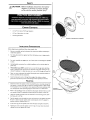
<Q1"
Example
of
standard
door
installation
,
Rear
Deck
Example
of
rear
deck
installation

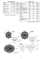
PHYSICAL
DIMENSIONS
SPECIFICATIONS
PRIME
R152
Rl653
R1693
Trim
Ring
Diameter-inch
6.10
9.06
7.56
x
10.20
(mm)
(154.6)
(178.00)
(192.0
x
259.0)
Trim
Ring
Height-inch
0.70
0.67
5.39
(mm)
(17.85) (17.08)
(23.00)
Mounting
Diameter-inch
4.78
5.61
6.02
x
6.74
(mm)
(121.0)
(147.5)
(153.0
x
222.0)
Mounting
Depth-inch
1.91
2.00
2.65
(mm)
(49.5) (51.2)
(72.4)
Screw
Hole
Diameter-inch
5.41
6.46
See
Below
(mm)
(137.5) (164.0)
See
Below
Specifications
subject
to
change
without
notice
PRIME
R152
Rl653
R1693
Nominal
Diameter
-
inch
5.25
6.5
6x9
(mm)
(133.4) (165.1)
(152.4
x
228.6)
Description
2-Way
3-Way
3-Way
Nominal
Impedance
(ohms)
4
4 4
Frequency
Response
(Hz)
53-22kHz
48-22kHz
48-22kHz
Voice
Coil
Diameter
-
inch
1.0
1.25 1.25
(em)
(2.54)
(3.23)
(3.23)
Fs
-
Free
Air
Resonance
(Hz)
74
67 66
Qts
0.91
0.78
0.81
Vas
-
cu.
ft.
0.27 0.53
0.64
(Liter)
(7.6)
(14.9) (18.0)
Xmax
-
inch
0.13
..
0.17 0.20
(em)
(0.34)
(0.43)
(0.51)
SPL
(dB
@
1w/1m)
87
89
90
Power
Handling-Watts
(RMS)
35
40
60
(Peak)
70
80
120
Specifications
subject
to
change
without
notice
4.57"
(115.96mm)
6.48"
---
(164.5mm) -
R1693
, 3.89"
(98.85mm)
2.85"
(72.40mm)
0.67"
(17.09mm)
R1653
8.74"
(222.00mm)
6.46"
(164.00mm)
=
_--..-1.-
r I
__
= I
~17'd
I
(6823~~m)
~
• 2.0" i
t
:J
(51.20mm) I
" I I
581"
(147.50mm)
,
/'
%
(])
~
"-...
118"
tl-==~====-~'-~======:JI
(~0.05mm)
0.70"
(17.85mm)
S:i2
'----
10.20" x 7.56"
(259.0mm x 192.0mm)
R152
o
5.41"
(137.5mm)
3.83"
-(97.23mm)
3

Fran~ais
-t MISE
EN
GARDE:
avant
d'entamer
I'installation,
deconnectez
la
Lll
broche
negative (-)
de
la
batterie
pour
eviter
tout
risque
de
blessures,
d'incendie
ou
de
dommages
it
I'apparel!.
PRATIQUEZ
UNE
ECOUTE
SANS
RISQUESMD
Une eXposition continue a
des
niveaux de pression acoustlque supeneurs
a J
00
dB
peue causer une perce
d'acUite
auditive permanence Les
systemes audio de forte
pUissance
pour auto peuvent produll e des
mveaux de presSion acoustlque bIen au-dela de
130
dB
Fa,tes preuve de
bon sens
et
pratlquez une
ecoute
sans nsques
Notes
pour
I'installation
Avant de
commencer
J'installation. suivez les
rcgles
ci·dessous :
I.
Veiflez
a bien lire
et
comprendre
les
instructions avant d'essayer d'installer
les
haut-parleurs.
2.
Par mesure de securite, debranchez
Ie
fiI
negatif de
la
batterie avant de com-
mencer
I'installation.
3.
Pour faciliter
Ie
montage des haut-parleurs,
if
est
conseille d'installer tous
les
dbles
au
prealable.
4.
Utilisez des connecteurs de haute qualite pour assurer une installation fiable
et
reduire
au
minimum
la
perte
de
signal
eu
de puissance.
S.
Reflechissez bien avant de percer.Veillez ane
pas
couper au percer
Ie
reser-
voir d'essence,
Ie
dblage
electrique ou les conduites
de
carburant. de freinage
hydraulique au de depression en travaillant sur
un
vehicule.
En
cas
d'installa-
tion sur
un
bateau. veillez ane
pas
couper ou percer
la
(oque
principale.
6.
Ne
jamais faire passer de
fils
sous
Ie vehi(ule. Leur installation aI'interieur
du
vehicule ou de
13
coque assure
la
meilleure protection.
7.
Evitez
de
faire passer des
fils
sur
des bords tranchants ou dans des orifices a
aretes
vives.
Utilisez
des
bagues
en caoutchouc ou
en
plastique
pour
proteger
les
fils
traversant une plaque de metal. notamment
Ie
tablier.
Montage
I.
Determinez I'emplacement des haut-parleurs.
Veillez
a ce que
la
surface plane soit
assez
grande pour assurer
un
contact unitorme du haut-parleur.Verifiez que I'em-
placement
est
assez profond pour
Ie
haut-parleur ;en cas
de
montage dans une
portiere, actionnez toutes
les
commandes (fenetres. serrures, etc.) iusqu'aux
extremites de leurs courses pour
vous
assurer qu'il n'y a
pas
d'obstruction.
2.
Consultez
Ie
tableau
des
caracteristiques pour determiner
Ie
diametre de I'orifice
a decouper pour votre modele de haut-parleur.
Le
gabarit fourni donne aussi
Ie
bon diametre de decoupe.
3.
Utilisez
Ie
gabarit fourni pour marquer I'emplacement des
vis
de montage. Percez
les
trous
avec
une meche de
1/8
de pouce (3,2 mm).
4.
Faites passer
les
fils
de haut-parleur a travers I'orifice decoupe
et
branchez-Ies
aux bornes du haut-parleur.
Veillez
abien respecter
la
polarite lors
du
branche-
ment.
La
borne positive
du
haut-parleur
est
indiquee par
un
« +
».
5.
Disposez j'anneau de garniture sur
Ie
haut-parleur
et
fixez-Ie
avec
quatre
(4)
vis.
6 Serrez
les
vis
jusqu'a ce que
Ie
haut-parleur
et
I'anneau de garniture soient bien
ajustes
de
fa~on
aprevenir
tout
c1iquetis.
Ne
pas
trop
serrer
les
vis.
4
Espanal
-t
PRECAUCION:
Antes
de
la
instalaci6n,
desconeete
el terminal
~
negativo
de
la
bateria (-)
para
prevenir
dana
a
la
unidad, incendio y/o
posibles lesiones.
PRACTIQUE
EL
SONIDO
SEGURO
EI
contacto contmuo con
mveles
de preSion de
sonodo
supenores a
100
dB
puede
causar
la
perduja permanente
de
la
audlclon
Los
sistemas
de
sonlde para
automovlles de alta petenCia pueden produClr
n1veles
de presion
de
somdo
supenores a
los
130
dB
Use
su
sentJdo comun y praetJque
el
sonldo segura
Consideraciones
para
la
instalaci6n
Antes
de
comenzar cualquier instalacion,
siga
escas
Simples
normas;
I.
AsegUrese de leer cuidadosamente y de entender
las
instrucciones antes de
tratar de instalar estos altavoces.
2.
Por seguridad. desconecte
el
conductor negativo de
la
bateda antes de comenzar
la
instalacion.
3.
Para facilitar
el
montaie, sugerimos que tienda todos los cables antes de montar
sus
altavoces
en
su
sirio.
4.
Utilice conectores de alta calidad para tener una instalacion confiable y para
reducir
al
minimo
las
perdidas de senal 0 de potencia.
S.
jPiense siempre antes
de
perlorar!
Tenga
cuidado
de
no
cortar
ni
perlorar en tan-
ques de combustible, tubedas de combustible. frenos 0 hidritul;cas, tuberias de
vado
0 cableado electrico
al
trabajar
en
un
vehiculo.
Si
la
instalation
se
hace en
un
bote. tenga
cui
dado de
no
cortar
ni
perforar a traves
del
casco principal.
6.
Nunca tienda cables abajo
del
vehiculo.Tender los cables adentro
del
vehiculo 0
casco
proporciona
la
mejor
protecd6n.
7.
Evite
tender cables arriba 0 a traves de bordes filosos. Use arandelas aislantes de
caucho para proteger los cables tendldos a traves de metal, especialmente
la
mampara cortafuegos.
Montaje
I.
Determine
ad6nde
se
montara
los
altavoces.Asegurese de que
haya
un
area sufi-
cientemente grande para rnontar de manera plana
el
alcavoz.Asegurese de que
el
lugar de montaie sea suficientemente profundo para que quepa
el
altavoz,
si
se
manta
en
una puerta. accione todas
las
funciones (ventanas. cerradura. etc.)
en
toda
su
gama de funcionamiento para asegurarse de que no
haya
obstrucciones.
2.
Consulte
la
tabla
de
especificaciones para determinar
cuales
son
los
diametros
correctos para
el
aguiero a
cortar
para su modelo de altavoz.
La
plantilla propor-
cionada tambien
Ie
da
la
medida correcta del recorte.
3.
Usando
la
plantilla proporcionada, marque los lugares para los tornillos de monta-
ie.
Perfore
los
agujeros usando una braea de
1/8
pulg.
4.
Tienda
los
cables del altavoz a traves
del
recorte y conecte a los terminales
del
altavoz.Asegurese de usar
la
polaridad correcta
al
conectar
los
cables.
EI
terminal
positivo del altavoz
est3.
identificade con
un
simbolo "+".
6.
Coloque
el
anillo
de acabado arriba del altavoz y montelo
en
su sitio usando cua-
tro
(4)
tornillos.
7.
Apriete los tornillos hasta que
el
altavoz y
el
anillo
de
acabado esten aiustados en
su
sitia para evitar vibraciones.
No
apriete demasiado
los
tornillos.
•

Deutsch
JjI.
VORSICHT:
Entfernen
Sie
vor
dem
Einbau
den
negative
Batteriepol,
~
um
Schiiden
am
Geriit,
Feuer
bzw.
mogliche
Verletzungen
zu
vermeiden.
PRAKTIZIEREN
SIE
SICHEREN
SOUND
Fortgesetzte Gerauschdruckpegel von uber 100
dB
konnen belm Menschen
zu
permanentem Horverlust fuhren Le,stungsstarke Autosoundsysterne konnen
Gerauschdruckpegel erzeugen,
dIe
we't
uber I
30
dB
IJegen
Bitte wenden S,e
gesunden Menschenverstand an und praktJZlercn
SIC
slcheren Sound
Eklbauuberlegungen
Befolgen Sie
vor
dem
Einbau diese einfachen Regeln;
I.
Lesen
Sie
die Anleitung
sorgf.iJtig.
bevor
Sie
versuchen diese Lautsprecher einzubauen.
2 Entfemen
Sie
vor dem
Einbau
aus Sicherheitsgriinden
clas
negative
Kabel
von
der
Batterie.
3.
Urn
die Montage zu erIeichtem.empfehlen wir aile
Kabel
vor
der
Befestigung Ihrer
Lautsprecher
zu
verlegen.
4. Verwenden
Sie
nur Qualitatssteeker, urn einen zuverliissigen
Einbau
zu
gew3hrleisten
und
Signal-
und Stromverlust
zu
minimieren.
5.
Denken
Sie
nach, bevor
Sie
bohren' Achten
Sie
darauf, nicht
in
den Benzintank, die
Benzin-, Brems-
oder
hydraulischen Leitungen,Vakuumleitungen
oder
Elektrokabel
zu
schneiden
oder
zu
bohren, wenn
Sie
am Fahrzeug arbeiten.Achten
Sie
beim
Einbau
in
einem Boot darauf, nicht durch den Bootsrumpf
zu
schneiden
oder
zu bohren.
6.
Verlegen
Sie
Kabel
nie unter dem Fahrzeug. Die
Kabel
im
Fahrzeug
oder
Bootsrumpf
zu
verlegen, bietet den besten Schutz.
7.
Venmeiden
Sie
es, Kabel iiber scharfe Kanten zu verlegenVerwenden
Sie
Gummi-
oder
Plastikringe.
urn
Kabel
zu
schiitzen. die durch
Metall
verlegt werden (besonders die
Feuerwand).
Befestigung
I.
Entscheiden.
wo
die Lautsprecher befestigt werden sollen. Gew.ihrleisten,
class
der
Platz ausreicht. um den Lautsprecher gteichmallig zu befestigen. Gew3hrleisten, dass
die Befestigungsstelle ausreichendeTiefe fur den Lautsprecher
hat;
beim Einbau
in
einerTiire aile Funktionen (Fenster, Schloss usw.)
in
ihrem ganzen Bereich auspro-
bieren urn zu gew.ihrleisten,
class
keine B10ckierung eintritt.
2. Die Tabelle
in
den
Technischen Daten gibt den richtigen Lochdurchmesser fur Ihr
LautsprechermodeU zum Ausschneiden
an.
Die beiliegende Schablone zeigt ebenfaJls
die richtige Ausschneidegrolle
an.
3.
Mit
der
beiliegenden Schablone die Stellen fiir die Befestigungsschrauben markieren.
Die Locher mit einer
1/8-Zol1
(3,2
mm) Bohrerspitze bohren.
4.
Die Lautsprecherkabel durch das Loch fiihren und
an
den Lautsprecherausgiingen
anschliellen.
Beim
Anschliellen
der
Kabel die ordnungsgemalle Polaritat beachten.
Der
positive Anschluss des Lautsprechers ist mit einem ,,+" markiert.
5.
Den Zierring iiber den Lautsprecher legen und mit 4 (vier) Schrauben an seinem
Platz befestigen.
6.
Die Schrauben anziehen, bis
der
Lautsprecher und
der
Zierring eng an ihrem Platz
anliegen,
urn
Klappem zu verhindem. Die Schrauben nicht
zu
fest anziehen.
s
Italiano
JjI.
ATTENZIONE:
Prima
dell'installazione,
scollegate
il
terminale
Ll..:i.
negativo
(-) della
batteria
per
evitare
danni
all'unitil,
pericoli
d'incendio
eJo
potenziali
lesioni
personali.
OSSERVATE LE
REGOLE
DEL
"SUONO
SENZA
PERICOLl"
I 1 (
)-.,1
"lie
eSf)'J'I2'I
I
)1
e 1
II"t~11
dl
\-
....
1
f"
,'J'
)('
l~I'
1
,-,1
cl.l
~'I
:,Opl
J.
del
I
(,L!
jp.
f:'c,':>"
,'10
'
LSirf'
I,:
[~O,
rl
j I
P(Crn"l
on·
nt('
ie'
,\
~
'I
i(
~~I
)1
h.J
-..
C 11t!
~l')~U
~'1
pn
--Ul
)
~\IO(Jt
,0,
.t..,q
~
_~
l'~SlJlll_
lC
~'
I)'
I
'J
-"':
:
~
1\
L'....
...
l.l
II)
...
)I~c,e~""'--,CI'-.J-..',r'.J':..1l"E'e
r~2'
"\'1
-'~L;"':.rrlL<
iJ'
(
Considerazioni sull'installazione
Prima
di
iniziare qualsiasi operazione d'installazione.
vi
consigliamo
di
seguire
queste
semplici regole;
I. Assicuratevi
di
aver letta
tutte
Ie
istruzioni con cura e
di
averle capite prima
di
effet-
tuare
qualsiasi tentative dinstallazione neiconfronti dell'unici.
2.
Per motivi
di
sicurezza, scoUegate
il
cave negative
da/Ia
batteria prima
di
dare
I'avvio
all'installazione.
3.
Per facilitare
iI
montaggio.
vi
suggeriamo
di
far scorrere tutti i
fili
prima
di
montare
Ia
vostra
uniti nella sua ubicazione.
4.
Usate connettori
di
alta
qualiti per garantire un'installazione che dil aflidamento e per
ridurre
aI
minima
Ia
perdita
di
segoali
0
di
potenza
5.
State attenti prima
di
uapanare!
Cercate
di
non trapanare e
di
non incidere i serbatoi
della benzina;
Ie
condutture del carburante, dei
freni,
del sistema idraulico e a depres.
sione; nonche i
fili
elettrici quando state Iavorando su
qualsiasi
veicolo.
6.
Non
fate mai scorrere i
fili
SOtte
il
veicolo.Avrete
Ia
protezione migtiore faecendo
scorrere
i
fili
all'interne del veicolo.
7.
Evitate
di
far scorrere i
fili
sopra 0 attraverso delle estremiti
affilate.
Usate guamizioni
di
tenuta
in
gamma 0
in
plastica per proteggere
qualsiasi
filo
che
passi
attraverso
del
metallo, soprattutto
il
parafiamma.
Montaggio
I.
Decidete dove montare
gti
a1toparlanti.Assicuratevi che sia un'area abbastanza
grande
per
poter
montare I'altoparlante a
Iivello
e abbastanza profonda per poterlo
collocare comedamente.Se
10
montate
all'intemo
di
uno sportello. controllate
tutte
Ie
funzioni (finestre. serrature, ecc.), una
alia
volta.
per
assicurarvi
che
non
ci
siano
ostruzioni.
2 Fate rilerimento alia tabella delle specifiche
per
stabilire
il
diametro
corretto
del foro
che dovrete praticare
per
II
modello del vostro altoparlante.
La
mascherina
in
dowione
fornisee anche
la
misura giusta
per
il
foro
di
ritaglio.
3.
Utilizzando
la
mascherina
in
dowione
segnare
Ie
posizioni delle
viti
di
montaggio.
Praticare i fori con una punta da trapano
di
1/8
di
pollice
(3,2
mm).
4. Passare i
cavi
del diffusore tramite I'apertura e collegarli
ai
terminali.Verifcare che
Ia
polarita sia
corretta
quando
si
eollegano i
cavi.
II
terminale positivo del diffusore e
identificato dal
"+".
5.
Adattare I'anello
di
finitura sui diffusore e montare
in
posizione servendosi delle
quattro
(4)
viti.
6.
Per evitare
rumore
dovuto a vibrazioni serrare
Ie
viti
finche
il
diffusore e I'anello
di
finitura non siano saldamente
in
posizione. Non serrare
Ie
viti
in
modo
eccessivo.

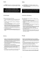
FEATURES
Rl52
• 0.5"
Balanced
Dome
MYLAR
Tweeter
•
Mica
injected
polypropylene
cone
•
Cold
Rolled
Steel
Frame
Rl653
•
Piezo
Super
MYLAR
Tweeter
• 0.5"
Balanced
Dome
MYLAR
Tweeter
•
Mica
injected
polypropylene
cone
•
Cold
Rolled
Steel
Frame
Rl693
• 0.5"
Balanced
Dome
MYLAR
Tweeter
• 1.75"
Midrange
MYLAR
Speaker
•
Mica
injected
polypropylene
cone
•
Cold
Rolled
Steel
Frame
Rockford
Fosgate
Rockford Corporation
600 South Rockford Drive
Tempe.Arizona 85281
U.S.A.
In
U.S.A..
(480) 967-3565 -
Customer
Service 1-800-669-9899
www.rockfordfosgate.com
6

LIMITED
WARRANTY
STATEMENT
.
Rockford Corporation offers a limited warranty on Rockford Fosgate products on the following terms:
Length
of
Warranty
Speakers - I Year. Any Factory Refurbished Product - 90
days
(receipt required)
What
is
Covered
This warranty applies only
to
Rockford Fosgate products sold
to
consumers
by
Authorized Rockford Fosgate
Dealers
in
the
United States ofAmerica
or
its
possessions. Product purchased
by
consumers from
an
Authorized Rockford Fosgate Dealer
in
another country are covered only
by
that country's Distributor and
not
by
Rockford Corporation.
Who
;s
Covered
This warranty covers only the original purchaser
of
Rockford product purchased from
an
Authorized
Rockford Fosgate Dealer
in
the
United States.
In
order
to
receive service,
the
purchaser must provide
Rockford with a copy
of
the
receipt stating
the
customer name, dealer name, product purchased and date of
purchase. Products found
to
be defective during
the
warranty period
will
be repaired
or
replaced
(with a product deemed
to
be equivalent)
at
Rockford's discretion.
What
is
Not Covered
I.
Damage caused
by
accident, abuse, improper operations, water, theft, shipping
2.Any cost
or
expense related
to
the removal
or
reinstallation of product
3.
Service performed
by
anyone
other
than Rockford
or
an Authorized Rockford Fosgate Service
Center
4.Any product which has had
the
serial number defaced, altered,
or
removed
5.
Subsequent damage
to
other
components
6.Any product purchased outside the
U.S.
7.Any product
not
purchased from
an
Authorized Rockford Fosgate Dealer
Umit
on
Implied Warranties
Any
implied
warranties
including
warranties offitness for use and merchantability are limited
in
duration
to
the
period of the express warranty
set
forth above. Some states do
not
allow limitations on the length ofan
implied
warranty, so this limitation
may
not
apply.
No
person
is
authorized
to
assume for Rockford Fosgate
any
other
liability
in
connection with the
sale
ofthe product.
How to Obtain Service
Contact theAuthorized Rockford Fosgate Dealer you purchased this product from.
If
you need further
assistance,
call
1-800-669-9899 for Rockford
Customer
Service.You must obtain an RA# (Return
Authorization number)
to
return
any
product
to
Rockford Fosgate.You are responsible for shipment
of product
to
Rockford.
fUWarranty
This product meets the current
EU
warranty requirements, see yourAuthorized dealer for details.
Check
our
website
for
additional
information
and
updates on these products.
www.RockfordFosgate.com
©2009
Rockford
Corporation.
All
rights reserved.
Rockford Fosgate,
the
Rockford Fosgate logo and
the
PRIME
logo
are
either
registered
trademarks
or
trademarks
of
Rockford
Corporation.
12/2008
B.M.
1230-55419-01
Printed in China

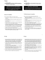
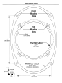
SPEAKER
MOUNTING
TEMPLATE
6.48"
(164.5mm)
--
--
-------
\
\
\
\
\
\
\
\
\
I
I
I
I
,
J
J
I
I
I
I
I
I
R152
H~~~"Cutout
~
(121.0mm)
---------
4.78"
(121.5mm)
R1693
Hole
Cutout
~
6.02" x 8.74"
~
(153.0mm x 222.0mm)
R152
'------
Mounting
Holes
R1693
,---,~---
Mounting
---~~
Holes
'-----
5.41"
(137.5mm)
Verify Scale
Before Using
Template
1.00"
(25.40mm)
8
-
 1
1
-
 2
2
-
 3
3
-
 4
4
-
 5
5
-
 6
6
-
 7
7
-
 8
8


Rockford Fosgate Prime R152 Installation & Operation Manual
- Categoria
- Altoparlanti per auto
- Tipo
- Installation & Operation Manual
- Questo manuale è adatto anche per
in altre lingue
- English: Rockford Fosgate Prime R152
- français: Rockford Fosgate Prime R152
- español: Rockford Fosgate Prime R152
- Deutsch: Rockford Fosgate Prime R152
Documenti correlati
-
Rockford Fosgate PRIME R1653 Installation & Operation Manual
-
Rockford Fosgate R1693 Manuale utente
-
 Rockford Fosgate PUNCH PM2T-S Installation & Operation Manual
-
Rockford Fosgate power T252-S Installation & Operation Manual
-
 Rockford Fosgate T4652-S Installation & Operation Manual
-
Rockford Fosgate T165-S Installation & Operation Manual
-
Rockford Fosgate T1 T-S Installation & Operation Manual
-
Rockford Fosgate Punch P152 Installation & Operation Manual
-
Rockford Fosgate PUNCH PPS8-6 Manuale del proprietario
-
Rockford Fosgate M282-Wake Installation & Operation

