CARLO GAVAZZI CLD2EB1BU24 Manuale utente
- Tipo
- Manuale utente

2-point level controller
Type CL with potentiometer
CLD2EB1BU24
User Manual
Bedienungsanleitung / Manuel de l’utilisateur / Manual del
Usuario / Manuale d’istruzione / Brugervejledning / 用户手册
µ-Processor based level controller for liquids with a wide sensitivity range
(like sewage water, chemicals, salt water etc.).
Max./min. control of charging/ discharging. The sensitivity is adjustable
by means of the potentiometer.
1 x 8A SPDT relay output.
• Conductive level controller
• Sensitivity adjustment from 250 Ω to 500 KΩ
• For filling or emptying applications
• Low-voltage AC electrodes
• Easy installation on DIN rails
• Rated operational voltage: 24 to 240 VAC/DC
• Output 1 x 8 A / 250 VAC, SPDT relay
• LED indication for: Output ON and Power ON
Product Description GB
Specifications
Rated operational voltage (U
B
)
Pin 2 & 10 20 to 265 VAC/DC, 45 to 65 Hz
Rated insulation voltage <2.0 kVAC (rms)
Rated impulse withstand voltage 4 kV (1.2/50 µs) (line/neutral)
Relay Rating (AgCdO) µ (micro gap)
Resistive loads AC1 8 A / 250 VAC (2500 VA)
DC1 1 A / 250 VDC (250 W)
or 10 A / 25 VDC (250 W)
Small induc. Loads AC15 0,4 A / 250 VAC
DC13 0,4 A / 30 VDC
Mechanical life (typical) ≥ 30 x 10
6
operations
@ 18’000 imp/h
Electrical life (typical) AC1 > 250’000 operations
Level probe supply Max. 5 VAC
Level probe current Max. 2 mA
Sensitivity 250Ω to 500KΩ
Factory settings standard range
“S” 100KΩ
Ranges L (Low sensitivity) 250 Ω to 5 KΩ, C
F
* = 4.7 nF
Ranges S (Standard sensitivity) 5 KΩ to 100 KΩ, C
F
* = 2.2 nF
Ranges H (High sensitivity) 50 KΩ to 500 KΩ, C
F
* = 1.0 nF
Operating frequency (f)
Relay output 1 HZ
Degree of protection IP 20 (IEC 60529, 60947-1)
Temperature
Operating -20º to +50ºC (-4º to + 122ºF)
Storage -40º to +85ºC (-40º to +185ºF)
UL Approvals cULus UL508
CE marking Yes
*C
F
= maximum Cable Capacitance
Mikroprozessor-gesteuerter Flüssigkeits-Füllstandsregler mit breitem
Empfindlichkeitsbereich (geeignet u.a. für Abwasser, Chemikalien und
Salzwasser).
Füllstandsmessung (Max. und Min.) für Füll- und Entleerungsanlagen.
Empfindlichkeitseinstellung durch Potentiometer.
SPDT-Relaisausgang 1 x 8A.
• Konduktiver Füllstandsregler
• Empfindlichkeit einstellbar von 250 Ω bis 500 kΩ
• Für Füll- und Entleerungs-Anlagen
• AC-Niederspannungselektroden
• Einfacher Einbau auf DIN-Schienen
• Nennbetriebsspannung: 24-240 VAC/DC
• Ausgabe 1 x 8 A /250 VAC, SPDT-Relais
• LED-Anzeige für: Ausgang EIN und Gerät EIN
Produktbeschreibung D
Eigenschaften
Nennbetriebsspannung (U
B
)
Pin 2 & 10 20 bis 265 VAC/DC, 45 bis 65 HZ
Nennisolierspannung <2,0 kVAC (eff.)
Nennstehstoßspannung 4 kV (1,2/50 µs) (Leiter/Neutral)
Relais (AgCdO) µ (Mikrokontakt)
Ohmsche Last AC1 8 A / 250 VAC (2500 VA)
DC1 1 A / 250 VDC (250 W) bzw.
10 A / 25 VDC (250 W)
Induk. Kleinlast AC15 0,4 A/ 250 VAC
DC13 0,4 A / 30 VDC
Mechanische Lebensdauer (typ.) ≥ 30 x 10
6
Schaltzyklen
bei 18.000 Imp./h
Elektrische Lebensdauer (typ.)
AC1 > 250.000 Schaltzyklen
Leistung Füllstandssensor Max. 5 VAC
Strom Füllstandssensor Max. 2 mA
Empfindlichkeit 250Ω bis 500 kΩ
Serienmäßige Voreinstellung
Bereich S: 100kΩ
Bereich L (niedrige Empfindlichkeit) 250 Ω bis 5 kΩ, C
F
* = 4,7 nF
Bereich S (Standardempfindlichkeit) 5 kΩ bis 100 kΩ, C
F
* = 2,2 nF
Bereich H (hohe Empfindlichkeit) 50 kΩ bis 500 kΩ, C
F
* = 1,0 nF
Betriebsfrequenz (f)
Relaisausgang 1 Hz
Schutzart IP 20 (IEC 60529, 60947-1)
Temperatur
Betrieb -20 bis +50 ºC
Lagerung -40 bis +85 ºC
UL-Zulassungen cULus UL508
CE-Kennzeichnung Ja
*C
F
= max. Kabelkapazität
Régulateur de niveau basé sur le processeur µ pour liquides avec une
large plage de sensibilité (par ex. eaux d’égout, produits chimiques, eau
saline, etc.).
Régulation max./min. charge/décharge. La sensibilité est réglable à l’aide
du potentiomètre.
Sortie relais 1 X 8A SPDT.
• Régulateur de niveau conducteur
• Réglage de sensibilité de 250 Ω à 500 KΩ
• Pour applications de remplissage ou de vidange
• Électrodes CA à faible tension
• Installation facile sur les rails DIN
• Tension de fonctionnement nominale : 24 à 240 VCA/CC
• Sortie 1x8A/250 relais VCA SPDT
• Indication DEL pour : Sortie MARCHE et puissance MARCHE
Description du produit F
Spécifications
Tension de fonctionnement nominale (U
B
)
Broches 2 et 10 20 à 265 VAC/DC, 45 à 65 Hz
Tension d’isolation nominale <2.0 kVAC (rms)
Tension nominale de résistance
impulsion 4 kV (1,2/50 μs) (ligne/neutre)
Régime nominal du relais (AgCdO) µ (espace micro)
Charges résistives CA1 8 A / 250 VCA (2500 VA)
CC1 1 A / 250 VCC (250 W) ou
10 A / 25 VCC (250 W)
Petites charges inductives CA15 0,4 A/ 250 VCA
CC13 0,4 A / 30 VCC
Longévité mécanique (typique) ≥ 30 x 10
6
opérations
@ 18 000 imp/h
Longévité électrique (typique)
CA1 > 250 000 opérations
Alimentation sonde de niveau Max. 5 VCA
Courant sonde de niveau Max. 2 mA
Sensibilité 250Ω à 500KΩ
Plage standard de réglage
usine “S” 100KΩ
Plages L (Faible sensibilité) 250 Ω à 5 KΩ, CF* = 4,7 nF
Plages S (Sensibilité standard) 5 KΩ à 100 KΩ, CF* = 2,2 nF
Plages H (Forte sensibilité) 50 KΩ à 500 KΩ, CF* = 1,0 nF
Fréquence de fonctionnement (f)
Sortie relais 1 HZ
Degré de protection IP 20 (IEC 60529, 60947-1)
Température
Fonctionnement -20º à +50ºC
Stockage -40º à +85ºC
Certification cULus UL508
Marquage CE Oui
*C
F
= capacité maximale du câble
Control de nivel basado en microprocesador para líquidos con un amplio
rango de sensibilidad (aguas residuales, productos químicos, agua
sa lada, etc.).
Control máx./mín. de carga/ descarga. La sensibilidad se ajusta median-
te potenciómetro.
Salida de relé SPDT 1 x 8A.
• Controlador de nivel conductivo
• Ajuste de sensibilidad de 250 Ω a 500 KΩ
• Para aplicaciones de llenado y vaciado
• Electrodos de CA de baja tensión
• Fácil instalación a carril DIN
• Tensión de funcionamiento nominal: 24 a 240 VCA/CC
• Salida de relé: 1 x 8A/250VCA, SPDT
• Indicación LED para: Salida y alimentación conectadas
Descripción del producto E
Especificaciones
Tensión nominal de funcionamiento (U
B
)
Patillas 2 y 10 20 a 265 VCA/CC, 45 a 65 Hz
Tensión nominal de aislamiento <2,0 kVCA (rms)
Impulso de tensión nominal
soportada 4 kV (1,2/50 µs) (línea-neutro)
Clasificación de contactos (AgCdO) µ (microgap)
Cargas resistivas AC1 8 A / 250 VCA (2500 VA)
DC1 1 A / 250 VCC (250 W) ó
10 A / 25 VCC (250 W)
Pequeñas cargas inductivas AC15 0,4 A / 250 VCA
DC13 0,4 A / 30 VCC
Vida útil mecánica (típica) ≥ 30 x 10
6
operaciones
@ 18.000 pulsos/h
Vida útil eléctrica (típica) AC1 > 250.000 operaciones
Alimentación de la sonda de nivel Máx. 5 VCA
Intensidad en la sonda de nivel Máx. 2 mA
Sensibilidad 250Ω a 500KΩ
Rango “S” estándar de ajuste de
fábrica 100KΩ
Rango L (sensibilidad baja) 250 Ω a 5 KΩ, CF* = 4,7 nF
Rango S (sensibilidad estándar) 5 KΩ a 100 KΩ, CF* = 2,2 nF
Rango H (sensibilidad alta) 50 KΩ a 500 KΩ, CF* = 1,0 nF
Frecuencia de funcionamiento (f)
Salida del relé 1 Hz
Grado de protección IP 20 (IEC 60529, 60947-1)
Temperatura
Funcionamiento -20º a +50ºC
Almacenamiento -40º a +85ºC
Homologación cULus UL508
Marca CE Sí
*C
F
= máxima capacitancia del cable
A1
A2
Y1
Y2
Y3
(PE)
12 14
11
Ref
Relay 1
Lo
Hi
Example 1
A1
A2
Y1
Y2
Y3
(PE)
12 14
11
Ref
Relay 1
Lo
Hi
Beispiel 1
A1
A2
Y1
Y2
Y3
(PE)
12 14
11
Ref
Relay 1
Lo
Hi
Exemple 1
A1
A2
Y1
Y2
Y3
(PE)
12 14
11
Ref
Relay 1
Lo
Hi
Ejemplo 1
2-punkt-Füllstandsregler
Typ CL mit Potentiometer
Régulateur du niveau à 2 points
Type CL avec potentiométre
Controlador de nivel en 2 puntos
Modelo CL con potenciómetro
Controllore di livello a 2 punti
Tipo CL con potenziometro
2-punkts niveaustyreenhed
CL-type med potentiometer
2极式液位控制器
电位计调节
Anschlusskabel
PVC-Kabel (2 bis 4 Adern), normal geschirmt. Leitungslänge max.
100 m. Der Widerstand zwischen Leiter und Masse muss mindestens
500 k betragen. Das Kabel zwischen Fühlerkopf und Regler soll-
te abgeschirmt sein (insbesondere bei Verlegung direkt neben dem
Stromversorgungskabel). Die Abschirmung muss an die Referenz ange-
schlossen werden. Die Anschlussklemme für die Referenz muss mit der
Schutzerde (PE) verbunden werden
Beispiel 1
Das Diagramm zeigt eine Zweipunkt-Füllstandsmessung. Die Relais
sprechen auf den Niederwechselstrom an, der zwischen den Elektroden
in der Flüssigkeit fließt.
Der Referenzpunkt (Ref) muss mit dem Behälter elektrisch leitend ver-
bunden sein; bei Behältern aus nicht leitfähigem Material muss er mit
einer Zusatzelektrode verbunden werden. Der Anschluss erfolgt an Y3.
Im Diagramm ist die Elektrode durch eine Punktlinie dargestellt.
Bemerkung! Brücken Sie die Anschluss klemmen Y1 und Y2, falls nur ein
Füllstand überwacht wird.
Funktionsweise
Câble de connexion
Câble PVC à 2, 3 ou 4 conducteurs, normalement blindé Longueur du
câble : max. 100 m. La résistance entre les noyaux et la terre doit être
d’au moins de 500k. Normalement, il est recommandé d’utiliser un câble
blindé entre la sonde et le régulateur, par exemple là où le câble est
placé en parallèle aux câbles de charge (réseau électrique). Le blindage
doit être raccordé à la réference (Ref). Le câble de réference doit être
raccordé à la terre (PE).
Exemple 1
Le diagramme indique le régulateur de niveau connecté comme régu-
lateur max. et min. Les relais réagissent au faible courant alternatif créé
lorsque les électrodes sont en contact avec le liquide,
La référence (Réf) doit être connectée au conteneur, ou si le conteneur
est un matériel non conducteur, à une électrode additionnelle. (À connec-
ter à la broche Y3).
(Dans le diagramme cette électrode est indiquée par la ligne pointillée).
Nota! Si un seul niveau de détection est souhaité - connecter ensemble
les 2 entrées Y1 et Y2.
Mode de fonctionnement
Cable de conexión
Cable PVC de 2, 3 o 4 conductores, normalmente apan tallado.
Longitud del cable: máx. 100 m. La resistencia entre el hilo conduc-
tor y tierra debe ser al menos de 500K. Normalmente, se recomienda
utilizar un cable apantallado entre la sonda y el relé, por ejemplo, si el
cable se coloca en paralelo con los cables de potencia (red).
Ejemplo 1
El diagrama muestra el control de nivel conectado como control máx. y
mín. Los relés reaccionan a la corriente alterna baja generada cuando los
electrodos están en contacto con el líquido.
La referencia (Ref) debe conectarse al depósito, o si el depósito, está
fabricado con un material no conductor, a un electrodo adicional. (Se
conectará a la patilla Y3).
(En el diagrama, dicho electrodo se indica con una línea de puntos).
NOTA! Si hay que detectar solo un nivel, interconectar las entradas Y1
e Y2.
Modo de funcionamientoMode of Operation
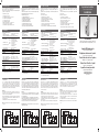
Connection cable
2, 3, or 4 conductor PVC cable, normally screened. Cable length: max.
100 m. The resistance between the cores and the ground must be
at least 500k. Normally, it is re commended to use a screened cable
between probe and controller, e.g. where the cable is placed in parallel to
the load cables (mains). The screen has to be connected to the reference
port (Ref) must be connected to Protective Earth (PE).
Example 1
The diagram shows the level control connected as max. and min. con-
trol. The re lays react to the low alternating current created when the
electrodes are in contact with the liquid.
The reference (Ref) must be connected to the container or if the container
consists of a non-conductive mater ial, to an additional electrode. (To be
connected to pin Y3).
(In the diagram this electrode is shown by the dotted line).
NB! If only one level detection is required - interconnect the two inputs
Y1 and Y2.

Wiring Diagram / Shaltplan / Diagramme de
câblage / Diagrama de conexiones / Schema
elettronico / Forbindelsesdiagram / 接线图
A1 A2
12 14 11
Y3Y2 Y1
Conductive Level Controller
Sensitivity
1
2
3
10
4
5 6
8
7
9
Fill Empty
L
S
H
L
S
H
Controllore di livello basato su processore µ per liquidi con una vasta
gamma di sensibilità (come liquami, prodotti chimici, acqua salata, ecc.).
Controllo massimo/minimo del carico/scarico. La sensibilità può essere
regolata con il potenziometro.
Uscita a relè SPDT 1 X 8A.
• Controllore di livello conduttivo
• Regolazione della sensibilità da 250 Ω a 500 KΩ
• Per applicazioni di riempimento o svuotamento
• Elettrodi CA a bassa tensione
• Facile installazione su guide DIN
• Tensione operativa nominale: 24 a 240 VCA/CC
• Uscita a relé SPDT 1 x 8 A / 250 VCA
• Indicazione LED per: Uscita ON e Alimentazione ON
Descrizione del prodotto I
Specifiche
Tensione nominale operativa (U
B
)
Pin 2 & 10 da 20 a 265 VCA, da 45 a 65 Hz
Tensione di isolamento nominale <2,0 kVCA (rms)
Tensione nominale di tenuta alle
scariche a impulso 4 kV (1.2/50 µs) (linea/neutro)
Classificazione relè (AgCdO) µ (micro gap)
Carichi resistivi CA1 8 A / 250 VCA (2500 VA)
CC1 1 A / 250 VCC (250 W) o
10 A / 25 VCC (250 W)
Piccoli carichi induttivi CA15 0,4 A250 VCA
CC13 0,4 A / 30 VCC
Durata meccanica (tipica) ≥ 30 x 10
6
operazioni
@ 18’000 imp/h
Durata elettrica (tipica) CA1 > 250’000 operazioni
Alimentazione sonda di livello Massimo 5 VCA
Corrente sonda di livello Massimo 2 mA
Sensibilità da 250Ωa 500KΩ
Gamma standard delle impo-
stazioni di fabbrica “S” 100KΩ
Gamme L (bassa sensibilità) da 250 Ω a 5 KΩ, CF* = 4,7 nF
Gamme S (sensibilità standard) da 5 KΩ a 100 KΩ, CF* = 2,2 nF
Gamme H (alta sensibilità) da 50 KΩ a 500 KΩ, CF* = 1,0 nF
Frequenza operativa (f)
Uscita a relè 1 HZ
Grado di protezione IP 20 /CEI 60529, 60947-1)
Temperatura
Operativa da -20º a +50ºC
Conservazione da -40º a +85ºC
Approvazioni cULus UL508
Marchio CE Sì
*C
F
= capacitanza massima del cavo
基于μ-处理器的液位控制器,用于具有宽感光度范围的液体(如污水,化
学品,盐水等)。
控制注水/排水的最大/最小值。灵敏度由电位计进行调节。
1个8A SPDT继电器输出。
· 电容式液位控制器
· 灵敏度可从250Ω调整到500KΩ
· 适合填充或排空的应用
· 低压交流电极
· 在DIN导轨上安装简便
· 额定工作电压: 24到240 VAC / DC
· 1个8A/250 VAC 单刀双掷继电器输出
· LED指示灯亮为:输出开和电源开
产品描述 CHN
产品规格
额定工作电压 (U
B
)
针脚 2 & 10 20 to 265 VAC/DC, 45 to 65 Hz
额定绝缘电压 <2.0 kVAC (rms)
额定冲击耐受电压 4 kV (1.2/50 μs) (火线/零线)
继电器额定值 (AgCdO) μ (微隙)
阻性负载 AC1 8 A / 250 VAC (2500 VA)
DC1 1 A / 250 VDC (250 W)
or 10 A / 25 VDC (250 W)
低电感负载 AC15 0,4 A / 250 VAC
DC13 0,4 A / 30 VDC
机械寿命(标准值) ≥ 30 x 10
6
次
@ 18’000 脉冲/小时
电子寿命(标准值) AC1 > 250’000 操作
液位探头电压 Max. 5 VAC
液位探头电流 Max. 2 mA
灵敏度 250Ω to 500KΩ
出厂设置标准范围 “S”100KΩ
范围L(低灵敏度) 250 Ω to 5 KΩ, CF* = 4.7 nF
范围S(标准灵敏度) 5 KΩ to 100 KΩ, CF* = 2.2 nF
范围H(高灵敏度 50 KΩ to 500 KΩ, CF* = 1.0 nF
工作频率 (f)
继电器输出 1 Hz
防护等级 IP 20 (IEC 60529, 60947-1)
温度
工作温度 -20°C to +50°C
储存温度 -40°C to +85°C
UL认证 cULus UL508
CE标志 Yes
*CF =最大电缆电容
A1
A2
Y1
Y2
Y3
(PE)
12 14
11
Ref
Relay 1
Lo
Hi
Esempio 1
A1
A2
Y1
Y2
Y3
(PE)
12 14
11
Ref
Relay 1
Lo
Hi
例1
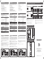
Mode of Operation / Funktionsweise / Mode de fonctionnement / Modo de funcionamiento /
Descrizione del prodotto / Produktbeskrivelse / 操作模式
Y3
Y3
Level
Level
Relay ON [11-14]
Relay ON [11-14]
Y1
Y1
Y2
Y2
Power supply ON
Power supply ON
Emptying
Filling
Time
Time
Fill
Empty
L
S
H
L
S
H
Fill
Empty
L
S
H
L
S
H
Power supply ON / Stromversorgung EIN / Alimentation électrique
MARCHE / Alimentación activada / Alimentatore ON / Strømforsyning
tændt / 电源开
Level / Füllstand / Niveau / Nivel / Livello / Level / 水平.等级
Time / Zeit / Temps / Tiempo / Tempo / Tid / 时间
Fill / Füllen / Remplir / Llenar / Riempi / Fylde / 满水
Empty / Leer / Vider / Vaciar / Svuota / Tømme / 空水
Filling / Füllen / Remplissage / Llenado / Riempimento / Påfyldning / 填充
Emptying / Entleeren / Vidange / Vaciado / Svuotamento / Tømning /
排空
Relay ON / Relais EIN / Relais MARCHE / Relé activado / Relé ON /
Relæ ON / 继电器开
17,5
90
67,2
5
43,8
45
Dimensions / Maßzeichnungen / Dimensions /
Dimensiones / Disegni dimensionali / Dimensioner
/ 尺寸图
Cavo di collegamento
cavo a 2, 3 o 4 conduttori in PVC, normalmente schermato. Lunghezza
del cavo: massimo 100 m. La resistenza tra il nucleo e la terra deve
essere almeno 500k. Normalmente, si consiglia di utilizzare un cavo
schermato tra sonda e controllore, ad esempio nel caso in cui il cavo
venga posizionato in parallelo rispetto ai cavi di carico (di alimentazione).
Lo schermo deve essere connesso al riferimento (Ref). L’ingresso di
riferimento(Ref) deve essere connesso a terra (PE).
Esempio 1
Il diagramma illustra il controllo di livello collegato come controllo massi-
mo e minimo. I relè reagiscono alla corrente alternata bassa che si crea
quando gli elettrodi sono a contatto con il liquido.
Il riferimento (Ref) deve essere collegato al contenitore o se nel conteni-
tore si trova un materiale non conduttivo, a un elettrodo aggiuntivo. (Da
collegare al pin Y3).
(Nel diagramma questo elettrodo è indicato con la linea tratteggiata.)
Nota! Se è richiesto il rilevamento di un solo livello - interconnettere i
due ingressi Y1 e Y2.
Modalità di funzionamento
电缆连接
2,3,或4个导线PVC电缆,通常是屏蔽电缆。电缆长度:最大100百米。芯
和接地之间的电阻必须至少为500K。通常,从探头和控制器之间,建议用
屏蔽电缆,例如当电缆被放置在平行于负载电缆(主电源)。屏蔽必须被
连接到基准端口(Ref),基准端口(Ref)必须与保护地线连接(PE)。
例1
该图显示了液位控制连接的最大和最小控制。当电极与液体接触时,产生
的低交变电流触发继电器。基准(Ref)必须连接到所述容器,如果所述容
器由非导电材料制成的,则需要到一个额外的电极。(要连接到引脚Y3)
(在该图中该电极是由虚线示出)
注意!
如果只需要一个液位检测 - 互连两个输入端Y1和Y2。
操作模式
CARLO GAVAZZI
www.gavazziautomation.com
Certified in accordance with ISO 9001
Gerätehersteller mit dem ISO 9001/EN 29 001 Zertifikat
Une société qualifiée selon ISO 9001
Empresa que cumple con ISO 9001
Certificato in conformità con l’IS0 9001
Kvalificeret i overensstemmelse med ISO 9001
按照 ISO 9001认证标准
MAN CLD2EB1BU24 MUL rev.00 - 07.2014
15-029-597
Mikroprocessorbaseret ni veau kontrolenhed til væsker med et bredt føl-
somhedsområde (såsom spildevand, kemikalier, saltvand osv.).
Maks./min.-styring af påfyldning/tømning. Følsomheden er justerbar ved
hjælp af potentiometer.
1 X 8A SPDT relæudgang.
• Ledende niveaukontrolenhed
• Justering af følsomhed fra 250 Ω til 500 KΩ
• Til påfyldnings- eller tømningsanlæg
• Lavspændingselektroder (AC)
• Nem installation på DIN-skinner
• Nominelt spændingsområde: 24 til 240 VAC/DC
• Udgang: 1x8A/250 V AC 2-polet relæ (SPDT)
• Lysdiodeindikation for: Udgang aktiveret og Power aktiveret
Produktbeskrivelse DK
Specifikationer
Nominelt spændingsområde (U
B
)
Ben 2 og 10 20 til 265 VAC/DC, 45 til 65 Hz
Nominel isoleringsspænding < 2,0 kV AC (rms)
Nominel stødspænding 4 kV (1,2/50 µs) (fase/neutral)
Relæbelastning (AgCdO) µ (mikrokontakt)
Ohmske belastninger AC1 8 A / 250 VAC (2500 VA)
DC1 1 A / 250 VDC (250 W)
or 10 A / 25 VDC (250 W)
Små induktive belastninger AC15 0,4 A / 250 VAC
DC13 0,4 A / 30 VDC
Mekanisk levetid (typisk) ≥ 30 x 10
6
aktiveringer
@ 18.000 impulser/time
Elektrisk levetid (typisk) AC1 > 250.000 aktiveringer
Niveaufølerforsyning Max. 5 VAC
Niveaufølerstrøm Max. 2 mA
Følsomhed 250Ω to 500KΩ
Fabriksindstilling: “S” 100KΩ
Område L (Lav følsomhed) 250Ω til 5KΩ, CF* = 4,7 nF
Område S (Standard følsomhed) 5KΩ til 100KΩ, CF* = 2,2 nF
Område H (Høj følsomhed) 50 KΩ til 500 KΩ, CF * = 1,0 nF
Tastefrekvens (f)
Relæudgang 1 HZ
Tæthedsgrad IP 20 (IEC 60529, 60947-1)
Temperatur
Drift -20º til +50ºC
Lager -40º til +85ºC
Godkendelser cULus UL508
CE-mærkning Ja
*CF = maksimal kabelkapacitet
A1
A2
Y1
Y2
Y3
(PE)
12 14
11
Ref
Relay 1
Lo
Hi
Eksempel 1
Tilslutningskabel
2, 3, 4 eller 5-leder PVC-kabel, normalt skærmet. Kabellængde: maks.
100 m. Modstanden mellem kernerne og jord skal være mindst 500k.
Normalt anbefales det at bruge et skærmet kabel mellem føler og
styreenhed, f.eks. hvis kablet er placeret parallelt med belastningskab-
lerne (strømforsyning). Afskærmningen skal tilsluttes referencen (Ref).
Referenceterminalen skal tilsluttes beskyttelseslederen (PE).
Eksempel 1
Diagrammet viser niveaustyringen tilsluttet som maks. og min. styring.
Relæet reagerer på den lave vekselstrøm der skabes når elektroderne er
i kontakt med væsken.
Referencen (Ref) skal forbindes til beholderen, eller, hvis beholderen er
lavet af ikke-ledende materiale, til en ekstra elektrode. (Skal sluttes til
ben Y3).
(I diagrammet er denne elektrode vist ved en stiplet linje).
Bemærk! Hvis det kun er nødvendigt med ét niveau, forbindes de to
indgange Y1 og Y2 med hinanden.
Funktionsbeskrivelse
继电器 1
-
 1
1
-
 2
2


CARLO GAVAZZI CLD2EB1BU24 Manuale utente
- Tipo
- Manuale utente
in altre lingue
Documenti correlati
-
CARLO GAVAZZI CLP2FA1B115 Guida d'installazione
-
-
-
-
-
CARLO GAVAZZI CB32CLN20TCFTAX Manuale utente
-