Grundfos CU 401 Installation And Operating Instructions Manual
- Tipo
- Installation And Operating Instructions Manual

CU 401
GRUNDFOS INSTRUCTIONS
Installation and operating instructions

2
Declaration of Conformity
We Grundfos declare under our sole responsibility that the product
CU 401, to which this declaration relates, is in conformity with the
Council Directives on the approximation of the laws of the EC Member
States relating to
– Electromagnetic compatibility (89/336/EEC).
Standards used: EN 61000-6-2 and EN 61000-6-3.
– Electrical equipment designed for use within certain voltage limits
(73/23/EEC) [95].
Standard used: EN 60335-1: 2002.
Konformitätserklärung
Wir Grundfos erklären in alleiniger Verantwortung, dass das Produkt
CU 401, auf das sich diese Erklärung bezieht, mit den folgenden
Richtlinien des Rates zur Angleichung der Rechtsvorschriften der EG-
Mitgliedstaaten übereinstimmt:
– Elektromagnetische Verträglichkeit (89/336/EWG).
Normen, die verwendet wurden: EN 61000-6-2 und EN 61000-6-3.
– Elektrische Betriebsmittel zur Verwendung innerhalb bestimmter
Spannungsgrenzen (73/23/EWG) [95].
Norm, die verwendet wurde: EN 60335-1: 2002.
Déclaration de Conformité
Nous Grundfos déclarons sous notre seule responsabilité que le
produit CU 401 auquel se réfère cette déclaration est conforme aux
Directives du Conseil concernant le rapprochement des législations des
Etats membres CE relatives à
– Compatibilité électromagnétique (89/336/CEE).
Standards utilisés: EN 61000-6-2 et EN 61000-6-3.
– Matériel électrique destiné à employer dans certaines limites
de tension (73/23/CEE) [95].
Standard utilisé: EN 60335-1: 2002.
Dichiarazione di Conformità
Noi Grundfos dichiariamo sotto la nostra esclusiva responsabilità che
il prodotto CU 401 al quale questa dichiarazione si riferisce è conforme
alle Direttive del Consiglio concernente il ravvicinamento delle legisla-
zioni degli Stati membri CE relative a
– Compatibilità elettromagnetica (89/336/CEE).
Standard usati: EN 61000-6-2 e EN 61000-6-3.
– Materiale elettrico destinato ad essere utilizzato entro certi limiti di
tensione (73/23/CEE) [95].
Standard usato: EN 60335-1: 2002.
Declaración de Conformidad
Nosotros Grundfos declaramos bajo nuestra única responsabilidad que
el producto CU 401 al cual se refiere esta declaración es conforme con
las Directivas del Consejo relativas a la aproximación de las legislacio-
nes de los Estados Miembros de la CE sobre
– Compatibilidad electromagnética (89/336/CEE).
Normas aplicadas: EN 61000-6-2 y EN 61000-6-3.
– Material eléctrico destinado a utilizarse con determinadas límites
de tensión (73/23/CEE) [95].
Norma aplicada: EN 60335-1: 2002.
Declaração de Conformidade
Nós Grundfos declaramos sob nossa única responsabilidade que o
produto CU 401 ao qual se refere esta declaração está em conformi-
dade com as Directivas do Conselho das Comunidades Europeias
relativas à aproximação das legislações dos Estados Membros respei-
tante à
– Compatibilidade electromagnética (89/336/CEE).
Normas utilizadas: EN 61000-6-2 e EN 61000-6-3.
– Material eléctrico destinado a ser utilizado dentro de certos limites
de tensão (73/23/CEE) [95].
Norma utilizada: EN 60335-1: 2002.
∆ήλωση Συµµόρφωσης
Εµείς η Grundfos δηλώνουµε µε αποκλειστική µας ευθύνη ότι το προιόν
CU 401, µε το οποίο σχετίζεται η παρούσα δήλωση, είναι σε συµφωνία
µε την Οδηγία του Συµβουλίου επί της σύγκλισης των νόµων των
Κρατών Mελών της Ευρωπαικής Ενωσης σε σχέση µε τα
– Ηλεκτροµαγνητική συµ
βατότητα (89/336/EEC).
Πρότυπα που χρησιµοποιήθηκαν: EN 61000-6-2 και EN 61000-6-3.
– Ηλεκτρικές συσκευές σχεδιασµένες γιά χρήση εντός ορισµένων
ορίων ηλεκτρικής τάσης (73/23/EEC) [95].
Πρότυπο που χρησιµοποιήθηκε: EN 60335-1: 2002.
Overeenkomstigheidsverklaring
Wij Grundfos verklaren geheel onder eigen verantwoordelijkheid dat
het product CU 401, waarop deze verklaring betrekking heeft in over-
eenstemming zijn met de Richtlijnen van de Raad inzake de onderlinge
aanpassing van de wetgevingen van de Lid-Staten betreffende
– Elektromagnetische compatibiliteit (89/336/EEG).
Normen: EN 61000-6-2 en EN 61000-6-3.
– Elektrisch materiaal bestemd voor gebruik binnen bepaalde
spanningsgrenzen (73/23/EEG) [95].
Norm: EN 60335-1: 2002.
Försäkran om överensstämmelse
Vi Grundfos försäkrar under ansvar, att produkten CU 401, som
omfattas av denna försäkran, är i överensstämmelse med Rådets
Direktiv om inbördes närmande till EU-medlemsstaternas lagstiftning,
avseende
– Elektromagnetisk kompatibilitet (89/336/EC).
Använda standarder: EN 61000-6-2 och EN 61000-6-3.
– Elektrisk material avsedd för användning inom vissa spännings-
gränser (73/23/EC) [95].
Använd standard: EN 60335-1: 2002.
Vastaavuusvakuutus
Me Grundfos vakuutamme yksin vastuullisesti, että tuote CU 401, jota
tämä vakuutus koskee, noudattavat direktiivejä jotka käsittelevät EY:n
jäsenvaltioiden koneellisia laitteita koskevien lakien yhdenmukaisuutta
seur.:
– Elektromagneettinen vastaavuus (89/336/EY).
Käytetyt standardit: EN 61000-6-2 ja EN 61000-6-3.
– Määrättyjen jänniterajoitusten puitteissa käytettävät sähköiset
laitteet (73/23/EY) [95].
Käytetty standardi: EN 60335-1: 2002.
Overensstemmelseserklæring
Vi Grundfos erklærer under ansvar, at produktet CU 401, som denne
erklæring omhandler, er i overensstemmelse med Rådets direktiver om
indbyrdes tilnærmelse til EF medlemsstaternes lovgivning om
– Elektromagnetisk kompatibilitet (89/336/EØF).
Anvendte standarder: EN 61000-6-2 og EN 61000-6-3.
– Elektrisk materiel bestemt til anvendelse inden for visse spændings-
grænser (73/23/EØF) [95].
Anvendt standard: EN 60335-1: 2002.
Deklaracja zgodności
My, Grundfos, oświadczamy z pełną odpowiedzialnością, że nasz
wyrób CU 401 którego deklaracja niniejsza dotyczy, zgodny jest z
następującymi wytycznymi Rady d/s ujednolicenia przepisów prawnych
krajów członkowskich EG:
– zgodność elektromagnetyczna (89/336/EWG),
zastosowane normy: EN 61000-6-2 i EN 61000-6-3.
–wyposażenie elektryczne do stosowania w określonym zakresie
napięć (73/23/EWG) [95],
zastosowana norma: EN 60335-1: 2002.

3
Свидетельство о соответствии
требованиям
Фирма Grundfos заявляет о своей исключительной
ответственности за то, чтоизделия модели CU 401, на которые
распространяется эта декларация, соответствуют нижеследующим
рекомендациям Совета по унификации правовых норм стран -
членов Европейского Союза:
– Электромагнитная совместимость (89/336/ЕЭС).
Применявшиеся стандарты: Евростандарт EN 61000-6-2 и
EN 61000-6-3.
– Электрические машины для эксплуатации в пределах
определенного диапазона значений напряжения
(73/23/ЕЭС)[95].
Применявшиеся стандарты
: Евростандарт EN 60335-1: 2002.
Konformitási nyilatkozat
Mi, a Grundfos egyedüli felelősséggel kijelentjük, hogy a CU 401
termék, amelyre jelen nyilatkozat vonatkozik, megfelel az Európai Unió
tagállamainak jogi irányelveit összehangoló tanács alábbi
irányelveinek:
– Elektromágneses összeférhetőség (89/336/EGK).
Alkalmazott szabványok: EN 61000-6-2 és EN 61000-6-3.
– Meghatározott feszültség határokon belül használt elektromos
eszközök (73/23/EGK) [95].
Alkalmazott szabvány: EN 60335-1: 2002.
Bjerringbro, 1st April 2006
Jan Strandgaard
Technical Director

4

5
CU 401
Installation and operating instructions 6
Montage- und Betriebsanleitung 20
Notice d'installation et d'entretien 35
Istruzioni di installazione e funzionamento 49
Instrucciones de instalación y funcionamiento 63
Instruções de instalação e funcionamento 77
Οδηγίες εγκατάστασης και λειτουργίας 91
Installatie- en bedieningsinstructies 105
Monterings- och driftsinstruktion 119
Asennus- ja käyttöohjeet 133
Monterings- og driftsinstruktion 147
Instrukcja montażu i eksploatacji 161
Руководство по монтажу и эксплуатации 176
Szerelési és üzemeltetési utasítás 191

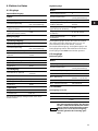
6
CONTENTS
Page
1. Applications 6
2. CU 401 control unit 7
3. Mounting 8
4. Indicator lights 9
5. Electrical data 10
5.1 Inputs 10
5.2 Outputs 10
5.3 Terminals 10
5.4 Conductors 11
6. Technical data 12
7. Module bus 12
7.1 UPS battery back-up 12
7.2 GENIbus (RS-485) 12
7.3 IR communication 12
7.4 Operator display (OD 401) 12
7.5 Communication to PC (RS-232) 12
8. Replacement of internal battery 13
9. Terminator 14
10. Replacement of CU 401 15
11. Replacement of modem 15
12. Network connection 16
13. Block diagram 17
14. Example of wiring diagram 18
15. Maintenance 19
16. Dimensions 19
17. Disposal 19
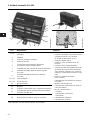
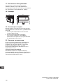
1. Applications
The CU 401 control unit is designed for the monitor-
ing and control of a number of Grundfos pumps.
Optimum pump operation is thereby ensured.
The CU 401 unit is the "brain" of a main control sys-
tem.
The CU 401 unit can be used alone or together with
various modules which can be connected as
required.
The number of pumps that can be monitored and
controlled depends on the modules in the system.
Prior to installation, read these installation
and operating instructions. Installation and
operation must comply with local regula-
tions and accepted codes of good prac-
tice.
All wires to units outside the control panel
must be of the type H05VV-F according to
CENELEC HD21 (to avoid injury from
touching wires).

7
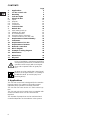
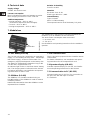
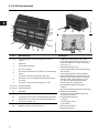
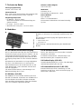
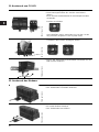
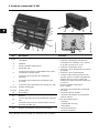
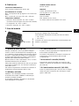
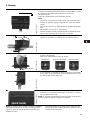
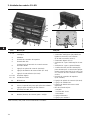
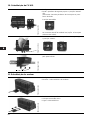
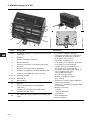
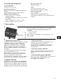
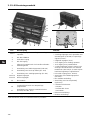
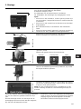
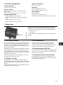
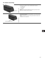
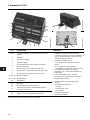
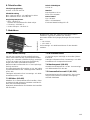
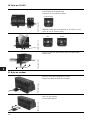
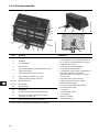
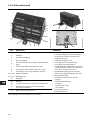
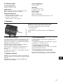
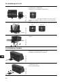
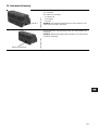
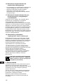
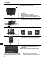
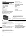
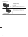
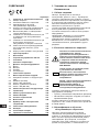
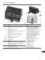
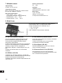
2. CU 401 control unit
* Not standard, but can be ordered from Grundfos.
TM02 6668 1303
TM02 6673 1303TM02 6674 1303
Pos. Description Functions
1 and 4 Analog inputs and supply for analog sensor • GENIbus communication (RS-485).
• 2 analog inputs which can be connected
to sensors with current (4-20 mA) or volt-
age (0-10 V).
• 6 digital inputs (24 V).
• 24 V output for sensor supply.
• 10 V output for potentiometer.
• 2 relay outputs (changeover relay) for
alarms for the control of external equip-
ment (400 VAC/2 A) like for instance
revolving warning light or horn.
• Pulse counter input (max. 10 kHz).
• Connection of operator display (OD 401).
• Module bus connection.
• Connection of UPS battery back-up
(optional).
• Communication buses:
- RS-232*
- Profibus-DP slave*
- DeviceNet.*
• Ethernet connection.*
• Modem connection.*
2 GENIbus
3 Pulse counter input
5 RS-232 input
6
IR communication via Grundfos remote control
R100
7 Connection for operator display (OD 401)
8 Connection for UPS battery back-up (PU 102)
9 Connection for power supply (PU 101)
10 and 14 Digital inputs
11 and 12 Relay outputs
13 Module bus
15 Modem*
16 CompactFlash card for application programs
17
Connection for external communication bus
(RS-232, RS-485, etc.)
18 Battery (internal back-up) for clock
13
14
12
11
10
1
2
3
4
5
6
789
15 16 17
18

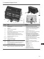
8
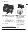
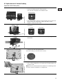
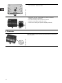
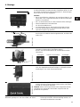
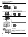
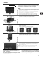
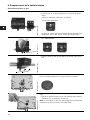
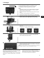
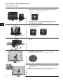
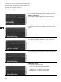
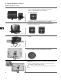
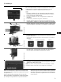
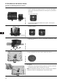
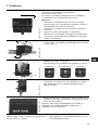
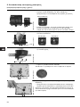
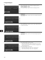
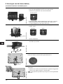
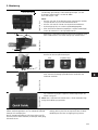
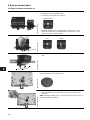
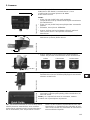
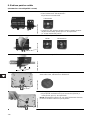
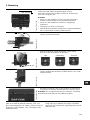
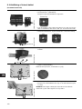
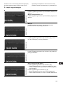
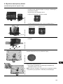
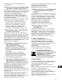
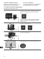
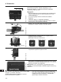
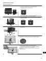
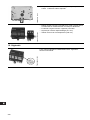
3. Mounting
For EMC reasons, the mounting plate must be made
of an electrically conducting material, e.g. iron.
The two mounting forks, one on each side of the
locking screw, must be fixed, e.g. with self-tapping
screws.
Place CU 401 in a closed control panel so that
access is only possible by means of tools or a key.
Hand out keys only to professional or specially
trained staff.
TM02 7129 2703
The CU 401 control unit must be mounted on a 35 mm stand-
ard DIN rail (EN 50022). Recommended height 7.5 mm.
The size of the unit appears in section 16. Dimensions.
All dimensions are stated in mm.
Note:
• Place the CU 401 unit so that there is sufficient space to
mount a modem, CompactFlash card and communication
bus.
• Place the CU 401 unit to the left of the expansion modules.
• Terminator, see section 9. Terminator.
• Fit the internal battery (supplied in separate packaging)
before the CU 401 unit is mounted on the DIN rail.
TM02 6667 1303
• Mount the CU 401 unit by first hooking the top of the unit to
the DIN rail and then the bottom.
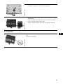
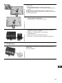
TM02 7135 2703
• Fit the terminals and turn the locking screw to position
"locked".
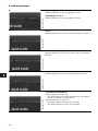
Use a 6 mm screwdriver for slotted screws.
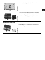
TM02 7133 2703
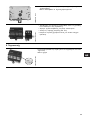
• If the modules are mounted vertically, it is recommended to
fit the end stops supplied to the DIN rail, i.e. below the low-
est module.
TM02 6670 1303
• Check the hardware when all modules have been mounted
and the power supply has been switched on. The indicator
light (P) must be green.
Note: If the CompactFlash card has been inserted, the module
mode will change according to the loaded program.
Min. 100 mm
1
2
UnlockedSlide positionLocked

9
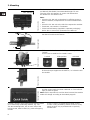
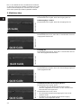
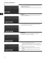
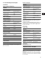
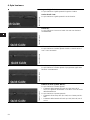
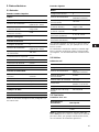
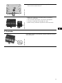
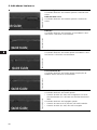
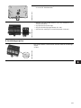
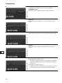
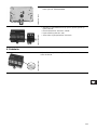
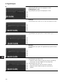
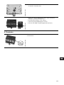
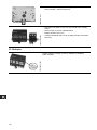
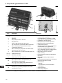
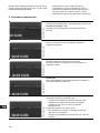
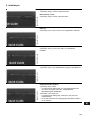
4. Indicator lights
TM02 6670 1303
Digital inputs 1 to 6:
The indicator light is yellow when the input is active.
Relay outputs 7 and 8:
The indicator light is yellow when the output is active.
TM02 6670 1303
Fault (F):
The indicator light is red if the CU 401 unit does not function
correctly.
TM02 6670 1303
Power (P):
The indicator light is green when the CU 401 unit is active
and OK.
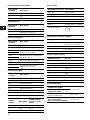
TM02 6670 1303
Run (R):
The indicator light is green when the application program is
running correctly.
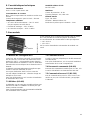
TM02 6670 1303
UPS battery back-up (BATT):
The indicator light is green when
• the battery for the UPS battery back-up (PU 102) is
charged and capable of powering the CU 401 in case of
supply failure.
The indicator light is off when
• the UPS battery back-up (PU 102) has not been fitted.
• the battery for the UPS battery back-up (PU 102) has not
been charged.

10
5. Electrical data
5.1 Inputs
Pulse counter input
Analog inputs
All analog inputs are short-circuit protected.
Digital inputs
The digital inputs are activated by short-circuiting the
input concerned to 0 V, e.g. with a contact or a relay.
The pulse counter input, digital inputs and analog
inputs have the same minus potential. The inputs are
not isolated from each other.
5.2 Outputs
Relay outputs
5.3 Terminals
Supply 24 V ±7%
Note: The supply module PU 101 must only be used
for the CU 401. If the PU 101 is used for other pur-
poses, e.g. sensor supply, the galvanic separation
will be ignored.
Pulse counter input
Data:
Max. frequency 10 kHz
Insulation voltage
50 V
(to system earth)
Output voltage
(open contact)
5 V, internal 1 kΩ
pull-up
Output current
(closed contact)
5 mA
Voltage input:
Voltage category II
Insulation voltage
50 V
(to system earth)
Insulation test voltage 700 VDC
Voltage range, optional
0-10 V
2-10 V
Input resistance 150 kΩ
Input resolution 2.4 mV
Accuracy at 25°C ±0.1%
Resolution 12 bits
Current input:
Current range, optional
0-20 mA
4-20 mA
Input resistance 250 Ω
Input resolution 5 µA
Accuracy at 25°C ±0.1%
Resolution 12 bits
Filter times:
Integration time 40 ms
Reading interval 160 ms
Data:
Voltage category II
Insulation voltage
50 V
(to system earth)
Insulation test voltage 700 VDC
Output voltage
(open contact)
24 V, internal 4.7 kΩ
pull-up
Output current
(closed contact)
5 mA
Input filter times
(software)
0, 15, 30, 45 ms
Input filter times
(hardware)
6 ms
Data:
Voltage category III
Insulation voltage
400 V
(to system earth)
Insulation test voltage 4 kVAC
Max. connection voltage 400 VAC
Max. load
400 VAC, 2 A, AC15/
24 VDC, 2 A, DC13
Min. load 5 V/10 mA
Max. load power AC/DC 400 VA/48 W
Terminal designation Description
+ +24 VDC max. 3 A
–0 VDC
Terminal designation Description
CNT Pulse counter/frequency
0 0 V
SHLD 0 V (screen)

11
GENIbus input
Analog inputs
Digital inputs
RS-232 input
Relay outputs
Operator display (OD 401)
Anybus (9-pole Sub-D)
5.4 Conductors
Terminal designation Description
A+ RS-485
Y Reference 0 V (screen)
B – RS-485
Terminal designation Description
AI1_U Analog input (voltage)
AI1_I Analog input (current)
+24 V
Supply for external trans-
ducer, max. 25 mA
0 V
+10 V
Supply for potentiometer,
min. 5 kΩ (+10 V)
0 V (screen)
AI2_U Analog input (voltage)
AI2_I Analog input (current)
+24 V
Supply for external trans-
ducer, max. 25 mA
0 V
Terminal designation Description
DI1 Digital input
DI2 Digital input
DI3 Digital input
DI4 Digital input
DI5 Digital input
DI6 Digital input
6 x 0 V Common zero point
Pin number Description
0 modem cable for
PC 9-pole Sub-D
2 RxD 3 to 2
3 TxD 2 to 3
5 GND 5 to 5
Terminal designation Description
DO1_NC Relay contact
DO1_NO Relay contact
DO1_C Relay contact - common
DO2_NC Relay contact
DO2_NO Relay contact
DO2_C Relay contact - common
Terminal designation Description
+
24 V supply for OD 401,
max. 500 mA
A+ RS-485
– 0 V (screen)
B – RS-485
Pin number RS-232
1DCD
2TxD
3RxD
4DTE
5GND
6DCE
7CTS
8RTS
9(RI)
Rigid conductors
0.2-2.5 mm
2
Flexible conductors
without insulated ferrule
Conductor size
(American measurement)
24-12 AWG
Flexible conductors
with insulated ferrule.
With/without plastic collar
0.2-1.5 mm
2
132
NC NO C
Changeover relay:

12
6. Technical data
Supply voltage
24 VDC ±7% from PU 101.
Current consumption
Max. 5.9 W when all inputs and outputs are active.
Max. charging current for PU 102 ~ 250 mA.
Ambient temperature
• During operation: –20°C to +60°C
(must not be exposed to direct sunlight).
• In stock: –25°C to +85°C.
• During transportation: –25°C to +85°C.
Relative air humidity
From 5% to 95%.
Materials
Enclosure class: IP 20.
Plastic type: Black PC / ABS.
Internal battery
Type: CR 2032.
Data: 3 V lithium battery.
The expected service life of the battery is 3 years.
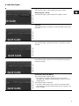
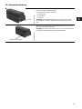
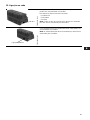
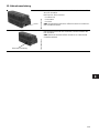
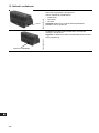
7. Module bus
7.1 UPS battery back-up
The CU 401 unit can be connected to an emergency
supply, i.e. UPS battery back-up (UPS – Uninterrupt-
ible Power Supply), via the PU 102 module. The
emergency supply time depends on the battery size.
The battery is automatically charged as long as the
CU 401 unit is supplied with 24 V.
An indicator light on the CU 401 front shows "battery
OK". The charging state is indicated on the PU 102.
For further information, see installation and operat-
ing instructions for the PU 102.
7.2 GENIbus (RS-485)
The GENIbus is a Grundfos standard using an
RS-485 interface. The GENIbus is used for several
Grundfos products.
Detailed documentation about the GENIbus can be
requested from Grundfos.
7.3 IR communication
The CU 401 unit is prepared for the Grundfos remote
control R100.
For further information, see installation and operat-
ing instructions for the CompactFlash card.
7.4 Operator display (OD 401)
Grundfos operator display for CU 401, see installa-
tion and operating instructions for the OD 401.
7.5 Communication to PC (RS-232)
Communication port for PC Tool. For connection to
the port, see "RS-232 input" in section
5.3 Terminals.
TM02 6668 1303
The module bus is the electrical connection between the
modules. Up to 12 modules can be connected.
The total current consumption must not exceed
• 2 A at 24 V and
• 1.5 A at 5 V.
See installation and operating instructions for the module in
question.
Module bus

13
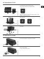
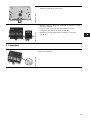
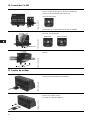
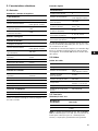
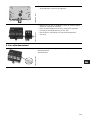
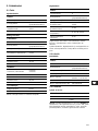
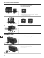
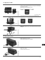
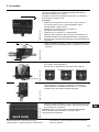
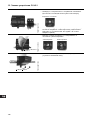
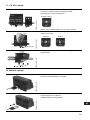
8. Replacement of internal battery
(expected service life 3 years)
TM02 7146 2703
• Switch off the power supply to the CU 401.
• Turn the locking screw to "slide position".
Use a 6 mm screwdriver for slotted screws.
• Push the modules, which are placed next to the CU 401 and
have contact via module bus, away from the CU 401
(approx. 15 mm to each side).
TM02 7135 2703
• Remove the terminals and turn the locking screw to position
"unlocked".
TM02 6667 1303
• Remove the CU 401 unit from the DIN rail by lifting it out at
the bottom.
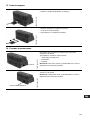
TM02 6674 1303
• Turn the CU 401 unit upside down.
Place the battery so that the text is visible.
.
TM02 6664 1303
The battery is kept into place by four locking elements.
• Use a small screwdriver or a similar tool to lift the battery out
of the CU 401.
Note: The tool used should not be made of a conducting mate-
rial and it must be suitable for a straight slot.
Slide position
UnlockedLocked
Battery

14
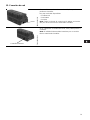
9. Terminator
TM02 6674 1303
• Fit a new battery according to the specifications.
See section 6. Technical data.
TM02 7146 2703
• Mount the CU 401 on the DIN rail, push the modules
together and fit the terminals.
• Turn the locking screw to position "locked".
• Switch on the power supply (PU 101).
• Set the clock using the operator display (OD 401).
TM02 6669 1303
The last module in the row must be terminated by a terminator.
See illustration.

15
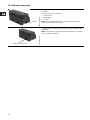
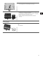
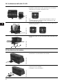
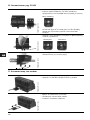
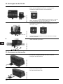
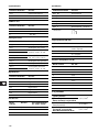
10. Replacement of CU 401
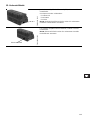
11. Replacement of modem
TM02 7146 2703
• Switch off the power supply to the CU 401.
• Turn the locking screw to "slide position".
Use a 6 mm screwdriver for slotted screws.
• Push the modules, which are placed next to the CU 401
and have contact via module bus, away from the CU 401
(approx. 15 mm to each side).
TM02 7135 2703
• Remove the terminals and turn the locking screw to posi-
tion "unlocked".
TM02 6667 1303
• Remove the CU 401 unit from the DIN rail by lifting it out at
the bottom.
Slide position
Unlocked
Locked
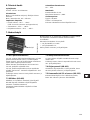
TM02 6673 1303
• Switch off the power supply to the CU 401.
• Remove the telephone cable from the module.
TM02 6671 1303
• Pull the modem out of the CU 401.
• Insert a new modem.
• Connect the telephone cable.

16
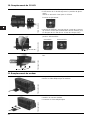
12. Network connection
TM02 6663 1303
If a communication bus is to be used, it can be ordered from
Grundfos.
Three variants are available:
• Profibus-DP
• DeviceNet
• RS-232.
Note: All communication buses must be mounted by an
authorized Grundfos workshop.
TM02 6663 1303
If an Ethernet module is to be used, it can be ordered from
Grundfos.
Note: The Ethernet module must be mounted by an author-
ized Grundfos workshop.
Ethernet connection

17
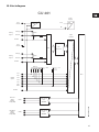
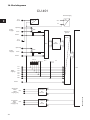
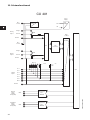
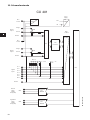
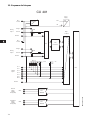
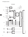
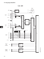
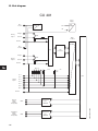
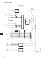
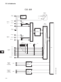
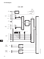
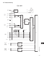
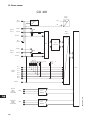
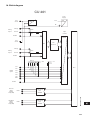
13. Block diagram
TM02 6705 1403
CU 401
Ref/0 V
DI 1
24 V
6x4.7 k
DI 2
DI 3
DI 4
DI 5
Digital
inputs
Power
Supply
0V
24 V
RIV
50 VAC
DI 6
RIV
50 VAC
Voltage
A/D
Converter
Ref/0 V
Current
250
120 k
830 k
24 V
25 mA
Analog
input 1
RIV
50 VAC
Voltage
Ref/0 V
Current
250
120 k
830 k
24 V
25 mA
Analog
input 2
Relay Circuit
RIV
400 VAC
DO 7
General
Alarm
Output
Relay (CO)
Relay Circuit
RIV
400 VAC
DO 8
High Water
Alarm
Output
Relay (CO)
MUX
CPU
CNT
3.5 k
Opto
Isolation
5 V

18
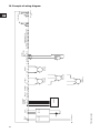
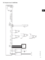
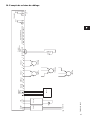
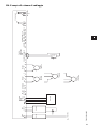
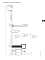
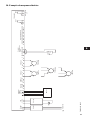
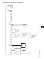
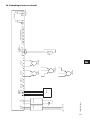
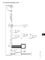
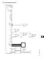
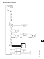
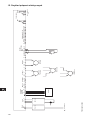
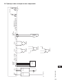
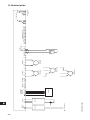
14. Example of wiring diagram
TM02 6454 0603
Power
24 V
UPS
Operator
display
OD 401 RS-232
PU 101 PU 102
123 A B
OD 401
1G1
Two-wire
4-20 mA
1I3
Three-wire
4-20 mA
1I3
Three-wire
0-10 V
1I3
GENIbus
OTxRx A Y B
0
24 V V I
Counter
input 10 kHz
Flow
SHLD CNTO SHLD
Digital Inputs DI 1-6
O DI1 O DI2
O
DI3 O DI4O DI5O DI6
Two-wire
4-20 mA
1I3
0
24 V V I
DO7
DO8
NC
NO
C
NC
NO
C
Max. 400 VAC
2 A
2 110-240 VAC
3P5
1
2
Wh
2 relay outputs
Analog 1 Analog 2

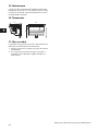
19
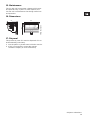
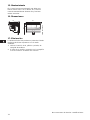
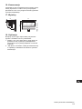
15. Maintenance
The CU 401 unit incorporates a battery which must
be replaced every 3 years. In other respects, the
CU 401 unit is maintenance-free during normal use
and operation.
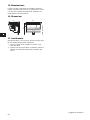
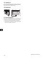
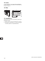
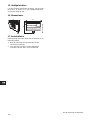
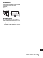
16. Dimensions
17. Disposal
This product or parts of it must be disposed of in an
environmentally sound way:
1. Use the public or private waste collection service.
2. If this is not possible, contact the nearest
Grundfos company or service workshop.
TM02 6715 1403
110
162
136
Subject to alterations.

20
INHALTSVERZEICHNIS
Seite
1. Sicherheitshinweise 20
1.1 Allgemeines 20
1.2 Kennzeichnung von Hinweisen 20
1.3 Personalqualifikation und -schulung 20
1.4 Gefahren bei Nichtbeachtung
der Sicherheitshinweise 20
1.5 Sicherheitsbewusstes Arbeiten 20
1.6 Sicherheitshinweise für den Betreiber/
Bediener 20
1.7 Sicherheitshinweise für Wartungs-,
Inspektions- und Montagearbeiten 21
1.8 Eigenmächtiger Umbau und Ersatzteil-
herstellung 21
1.9 Unzulässige Betriebsweisen 21
2. Verwendungszweck 21
3. CU 401 Steuereinheit 22
4. Montage 23
5. Meldeleuchten 24
6. Elektrische Daten 25
6.1 Eingänge 25
6.2 Ausgänge 25
6.3 Klemmen 25
6.4 Leiter 26
7. Technische Daten 27
8. Modulbus 27
8.1 USV-Batterienotstromversorgung 27
8.2 GENIbus (RS-485) 27
8.3 IR-Kommunikation 27
8.4 Bediendisplay (OD 401) 27
8.5 Kommunikation mit PC (RS-232) 27
9. Austausch der internen Batterie 28
10. Abschlusswiderstand 29
11. Austausch von CU 401 30
12. Austausch des Modems 30
13. Netzwerkverbindung 31
14. Blockdiagramm 32
15. Beispiel eines Schaltbildes 33
16. Wartung 34
17. Abmessungen 34
18. Entsorgung 34
1. Sicherheitshinweise
1.1 Allgemeines
Diese Montage- und Betriebsanleitung enthält grund-
legende Hinweise, die bei Installation, Betrieb und
Wartung zu beachten sind. Sie ist daher unbedingt
vor Montage und Inbetriebnahme vom Monteur
sowie dem zuständigen Fachpersonal/Betreiber zu
lesen. Sie muss ständig am Einsatzort der Anlage
verfügbar sein.
Es sind nicht nur die unter diesem Abschnitt "Sicher-
heitshinweise" aufgeführten, allgemeinen Sicher-
heitshinweise zu beachten, sondern auch die unter
den anderen Abschnitten eingefügten, speziellen
Sicherheitshinweise.
1.2 Kennzeichnung von Hinweisen
Direkt an der Anlage angebrachte Hinweise müssen
unbedingt beachtet und in vollständig lesbarem
Zustand gehalten werden.
1.3 Personalqualifikation und -schulung
Das Personal für Bedienung, Wartung, Inspektion
und Montage muss die entsprechende Qualifikation
für diese Arbeiten aufweisen.
Verantwortungsbereich, Zuständigkeit und die Über-
wachung des Personals müssen durch den Betreiber
genau geregelt sein.
1.4 Gefahren bei Nichtbeachtung der
Sicherheitshinweise
Die Nichtbeachtung der Sicherheitshinweise kann
sowohl eine Gefährdung für Personen als auch für
die Umwelt und Anlage zur Folge haben. Die Nicht-
beachtung der Sicherheitshinweise kann zum Ver-
lust jeglicher Schadenersatzansprüche führen.
Im einzelnen kann Nichtbeachtung beispielsweise
folgende Gefährdungen nach sich ziehen:
• Versagen wichtiger Funktionen der Anlage
• Versagen vorgeschriebener Methoden zur War-
tung und Instandhaltung
• Gefährdung von Personen durch elektrische und
mechanische Einwirkungen.
1.5 Sicherheitsbewusstes Arbeiten
Die in dieser Montage- und Betriebsanleitung aufge-
führten Sicherheitshinweise, die bestehenden natio-
nalen Vorschriften zur Unfallverhütung sowie even-
tuelle interne Arbeits-, Betriebs- und Sicherheits-
vorschriften des Betreibers, sind zu beachten.
1.6 Sicherheitshinweise für den Betreiber/
Bediener
Gefährdungen durch elektrische Energie sind aus-
zuschließen (Einzelheiten hierzu siehe z.B. in den
Vorschriften des VDE und der örtlichen Energiever-
sorgungsunternehmen).
Die in dieser Montage- und Betriebs-
anleitung enthaltenen Sicherheitshin-
weise, die bei Nichtbeachtung Gefähr-
dungen für Personen hervorrufen kön-
nen, sind mit allgemeinem Gefahren-
symbol "Sicherheitszeichen nach
DIN 4844-W9" besonders gekennzeich-
net.
Dieses Symbol finden Sie bei Sicher-
heitshinweisen, deren Nichtbeachtung
Gefahren für die Maschine und deren
Funktionen hervorrufen kann.
Hier stehen Ratschläge oder Hinweise,
die das Arbeiten erleichtern und für
einen sicheren Betrieb sorgen.
Achtung
Hinweis
La pagina si sta caricando...
La pagina si sta caricando...
La pagina si sta caricando...
La pagina si sta caricando...
La pagina si sta caricando...
La pagina si sta caricando...
La pagina si sta caricando...
La pagina si sta caricando...
La pagina si sta caricando...
La pagina si sta caricando...
La pagina si sta caricando...
La pagina si sta caricando...
La pagina si sta caricando...
La pagina si sta caricando...
La pagina si sta caricando...
La pagina si sta caricando...
La pagina si sta caricando...
La pagina si sta caricando...
La pagina si sta caricando...
La pagina si sta caricando...
La pagina si sta caricando...
La pagina si sta caricando...
La pagina si sta caricando...
La pagina si sta caricando...
La pagina si sta caricando...
La pagina si sta caricando...
La pagina si sta caricando...
La pagina si sta caricando...
La pagina si sta caricando...
La pagina si sta caricando...
La pagina si sta caricando...
La pagina si sta caricando...
La pagina si sta caricando...
La pagina si sta caricando...
La pagina si sta caricando...
La pagina si sta caricando...
La pagina si sta caricando...
La pagina si sta caricando...
La pagina si sta caricando...
La pagina si sta caricando...
La pagina si sta caricando...
La pagina si sta caricando...
La pagina si sta caricando...
La pagina si sta caricando...
La pagina si sta caricando...
La pagina si sta caricando...
La pagina si sta caricando...
La pagina si sta caricando...
La pagina si sta caricando...
La pagina si sta caricando...
La pagina si sta caricando...
La pagina si sta caricando...
La pagina si sta caricando...
La pagina si sta caricando...
La pagina si sta caricando...
La pagina si sta caricando...
La pagina si sta caricando...
La pagina si sta caricando...
La pagina si sta caricando...
La pagina si sta caricando...
La pagina si sta caricando...
La pagina si sta caricando...
La pagina si sta caricando...
La pagina si sta caricando...
La pagina si sta caricando...
La pagina si sta caricando...
La pagina si sta caricando...
La pagina si sta caricando...
La pagina si sta caricando...
La pagina si sta caricando...
La pagina si sta caricando...
La pagina si sta caricando...
La pagina si sta caricando...
La pagina si sta caricando...
La pagina si sta caricando...
La pagina si sta caricando...
La pagina si sta caricando...
La pagina si sta caricando...
La pagina si sta caricando...
La pagina si sta caricando...
La pagina si sta caricando...
La pagina si sta caricando...
La pagina si sta caricando...
La pagina si sta caricando...
La pagina si sta caricando...
La pagina si sta caricando...
La pagina si sta caricando...
La pagina si sta caricando...
La pagina si sta caricando...
La pagina si sta caricando...
La pagina si sta caricando...
La pagina si sta caricando...
La pagina si sta caricando...
La pagina si sta caricando...
La pagina si sta caricando...
La pagina si sta caricando...
La pagina si sta caricando...
La pagina si sta caricando...
La pagina si sta caricando...
La pagina si sta caricando...
La pagina si sta caricando...
La pagina si sta caricando...
La pagina si sta caricando...
La pagina si sta caricando...
La pagina si sta caricando...
La pagina si sta caricando...
La pagina si sta caricando...
La pagina si sta caricando...
La pagina si sta caricando...
La pagina si sta caricando...
La pagina si sta caricando...
La pagina si sta caricando...
La pagina si sta caricando...
La pagina si sta caricando...
La pagina si sta caricando...
La pagina si sta caricando...
La pagina si sta caricando...
La pagina si sta caricando...
La pagina si sta caricando...
La pagina si sta caricando...
La pagina si sta caricando...
La pagina si sta caricando...
La pagina si sta caricando...
La pagina si sta caricando...
La pagina si sta caricando...
La pagina si sta caricando...
La pagina si sta caricando...
La pagina si sta caricando...
La pagina si sta caricando...
La pagina si sta caricando...
La pagina si sta caricando...
La pagina si sta caricando...
La pagina si sta caricando...
La pagina si sta caricando...
La pagina si sta caricando...
La pagina si sta caricando...
La pagina si sta caricando...
La pagina si sta caricando...
La pagina si sta caricando...
La pagina si sta caricando...
La pagina si sta caricando...
La pagina si sta caricando...
La pagina si sta caricando...
La pagina si sta caricando...
La pagina si sta caricando...
La pagina si sta caricando...
La pagina si sta caricando...
La pagina si sta caricando...
La pagina si sta caricando...
La pagina si sta caricando...
La pagina si sta caricando...
La pagina si sta caricando...
La pagina si sta caricando...
La pagina si sta caricando...
La pagina si sta caricando...
La pagina si sta caricando...
La pagina si sta caricando...
La pagina si sta caricando...
La pagina si sta caricando...
La pagina si sta caricando...
La pagina si sta caricando...
La pagina si sta caricando...
La pagina si sta caricando...
La pagina si sta caricando...
La pagina si sta caricando...
La pagina si sta caricando...
La pagina si sta caricando...
La pagina si sta caricando...
La pagina si sta caricando...
La pagina si sta caricando...
La pagina si sta caricando...
La pagina si sta caricando...
La pagina si sta caricando...
La pagina si sta caricando...
La pagina si sta caricando...
La pagina si sta caricando...
La pagina si sta caricando...
La pagina si sta caricando...
La pagina si sta caricando...
La pagina si sta caricando...
La pagina si sta caricando...
La pagina si sta caricando...
La pagina si sta caricando...
La pagina si sta caricando...
La pagina si sta caricando...
La pagina si sta caricando...
La pagina si sta caricando...
La pagina si sta caricando...
-
 1
1
-
 2
2
-
 3
3
-
 4
4
-
 5
5
-
 6
6
-
 7
7
-
 8
8
-
 9
9
-
 10
10
-
 11
11
-
 12
12
-
 13
13
-
 14
14
-
 15
15
-
 16
16
-
 17
17
-
 18
18
-
 19
19
-
 20
20
-
 21
21
-
 22
22
-
 23
23
-
 24
24
-
 25
25
-
 26
26
-
 27
27
-
 28
28
-
 29
29
-
 30
30
-
 31
31
-
 32
32
-
 33
33
-
 34
34
-
 35
35
-
 36
36
-
 37
37
-
 38
38
-
 39
39
-
 40
40
-
 41
41
-
 42
42
-
 43
43
-
 44
44
-
 45
45
-
 46
46
-
 47
47
-
 48
48
-
 49
49
-
 50
50
-
 51
51
-
 52
52
-
 53
53
-
 54
54
-
 55
55
-
 56
56
-
 57
57
-
 58
58
-
 59
59
-
 60
60
-
 61
61
-
 62
62
-
 63
63
-
 64
64
-
 65
65
-
 66
66
-
 67
67
-
 68
68
-
 69
69
-
 70
70
-
 71
71
-
 72
72
-
 73
73
-
 74
74
-
 75
75
-
 76
76
-
 77
77
-
 78
78
-
 79
79
-
 80
80
-
 81
81
-
 82
82
-
 83
83
-
 84
84
-
 85
85
-
 86
86
-
 87
87
-
 88
88
-
 89
89
-
 90
90
-
 91
91
-
 92
92
-
 93
93
-
 94
94
-
 95
95
-
 96
96
-
 97
97
-
 98
98
-
 99
99
-
 100
100
-
 101
101
-
 102
102
-
 103
103
-
 104
104
-
 105
105
-
 106
106
-
 107
107
-
 108
108
-
 109
109
-
 110
110
-
 111
111
-
 112
112
-
 113
113
-
 114
114
-
 115
115
-
 116
116
-
 117
117
-
 118
118
-
 119
119
-
 120
120
-
 121
121
-
 122
122
-
 123
123
-
 124
124
-
 125
125
-
 126
126
-
 127
127
-
 128
128
-
 129
129
-
 130
130
-
 131
131
-
 132
132
-
 133
133
-
 134
134
-
 135
135
-
 136
136
-
 137
137
-
 138
138
-
 139
139
-
 140
140
-
 141
141
-
 142
142
-
 143
143
-
 144
144
-
 145
145
-
 146
146
-
 147
147
-
 148
148
-
 149
149
-
 150
150
-
 151
151
-
 152
152
-
 153
153
-
 154
154
-
 155
155
-
 156
156
-
 157
157
-
 158
158
-
 159
159
-
 160
160
-
 161
161
-
 162
162
-
 163
163
-
 164
164
-
 165
165
-
 166
166
-
 167
167
-
 168
168
-
 169
169
-
 170
170
-
 171
171
-
 172
172
-
 173
173
-
 174
174
-
 175
175
-
 176
176
-
 177
177
-
 178
178
-
 179
179
-
 180
180
-
 181
181
-
 182
182
-
 183
183
-
 184
184
-
 185
185
-
 186
186
-
 187
187
-
 188
188
-
 189
189
-
 190
190
-
 191
191
-
 192
192
-
 193
193
-
 194
194
-
 195
195
-
 196
196
-
 197
197
-
 198
198
-
 199
199
-
 200
200
-
 201
201
-
 202
202
-
 203
203
-
 204
204
-
 205
205
-
 206
206
-
 207
207
-
 208
208


Grundfos CU 401 Installation And Operating Instructions Manual
- Tipo
- Installation And Operating Instructions Manual
Documenti correlati
-
Grundfos R100 Installation And Operating Istructions
-
-
Grundfos MAGNA 25-100 N Installation And Operating Instructions Manual
-
-
-
-
-
Grundfos DME 375 Installation And Operating Instructions Manual
-
-