
Ultrasonic
Ultraschall / xxxxxxxxxxx / Ultrasonidos /
Sensori ad ultrasuoni / Ultrasonisk
Diffuse, Programmable Outputs
Abstandssensor, programmierbare Ausgänge /
cxcxcxcxcxcxcxcxcxc / Detección Directa, Salidas
Programables / Sensori a riflessione, uscite programmabili /
Diffuse, programmerbare udgange
Guardian 2
Combined motion and presence
detector for automatic sliding doors
Sensor für die Anwesenheits- und Bewegungserfassung bei
automatischen Schiebetüren
Détecteur de mouvement et de présence pour portes
automatiques coulissantes
Detector Combinado de Movimiento y Presencia para
Puertas Correderas Automáticas
Rilevatore combinato di movimento e presenza per porte
scorrevoli automatiche
Kombineret bevægelses- og tilstedeværelsessensor til
automatiske skydedøre
Original User Manual
Original-Bedienungsanleitung
Mode d’emploi original
Manual del usuario
Manuale d’istruzione originale
Original brugervejledning

2
ENGLISHDEUTSCHFRANÇAISESPAÑOLITALIANODANSK
Page 3
Seite 13
Page 23
Página 33
Pagina 43
Side 53

3
1
ENGLISH
FRANÇAIS
ESPAÑOL
ITALIANO
DANSK DEUTSCH
Photoelectric
Door Sensor, motion and presence
detection
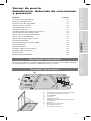
CONTENTS Page
Product Description .................................... 3
Component Guide ...................................... 3
Safety Instructions ...................................... 4
Opening the unit ....................................... 4
Mounting the sensor .................................... 5
Electrical connection .................................... 7
Teaching the presence zone .............................. 7
Dip-switch settings .................................... 10
Blanking of motion zone ................................ 11
Adjust sensitivity ...................................... 11
Presence time settings ................................. 12
Test input ............................................ 12
EC Declaration of Conformity ............................ 12
Maintenaince ......................................... 12
Specifications ........................................ 63
Operating Diagram .................................... 66
Wiring Diagram ....................................... 67
Dimensions .......................................... 67
Drilling Measurements .................................. 67
UL ................................................. 67
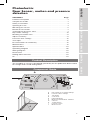
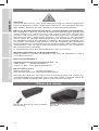
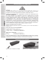
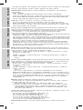
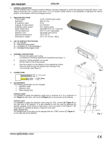
The Guardian 2 sensor is developed specifically for the pedestrian door market
for straight and curved sliding doors.
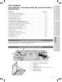
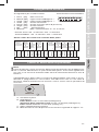
Product Description
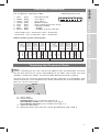
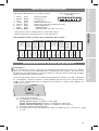
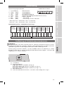
Component Guide
A
ON
DIP
123456
MIN MAX
TEST HIGH
SAFE NO
MOTION NO
UNI-DIR.
LOW
NC
NC
BI-DIR.
5 MIN
1 MIN
30 SEC
10 SEC
SENSITIVITY PRESENCE
TIME
MIN MAX MIN MAXMIN MAX
MOTION AREA ADJUSTMMENT
CENTER
LEFT
RIGHT
TEACH-IN
NOT COM-
PLIANT
COM-
PLIANT
GUARDIAN 2
A DIP-switches for initial settings
B Presence time settings
C Sensitivity
D Connector
E LED Indications
F Motion area limitation switches
G Camera
H Teach button
I Presence zone
J Motion zone
B
C
D
E
F
G
H
I
J

4
ENGLISHDEUTSCHFRANÇAISESPAÑOLITALIANODANSK
Safety Instructions
General:
The unit must only be operated at protective low voltage in conjunction with
safe electrical isolation. The unit must only be repaired by the supplier.
Never touch any electronic and optical components of the sensor.
Use as safety device according to the European Machinery Directive:
The Guardian 2 sensor has passed the EC Type Examinations according
to DIN 18650-1: 2005 § 5.7.4, EN 12978: 2003 and other relevant standards
and thus comply with the requirements of the European Machine Directive
(2006/42/EC), Appendix I. The sensor is TÜV-certified and is thus approved as
sole safety device when used with automatic sliding doors. Risk assessment,
correct installation, consideration of additional local standards as well as
observance of the required detection areas to secure hazardous areas during
the opening and closing of the door fall within the area of responsibility of the
person who installs the automatic door system.
Direct light into the sensor is not recommended.
Settings with relevance for the standards
Some functions permit settings that are not in accordance with DIN18650-1:
2005 § 5.7.2
Relevant for DIN18650-1
Presence time (page 10)
1 min, 5 min : in accordance with DIN18650-1
10 sec, 30 sec : not in accordance with DIN18650-1
DIP-switch 5 and 6
Compliant : in accordance with DIN18650-1
Not compliant : not in accordance with DIN18650-1
If DIP-switch 5 and 6 have been set to compliant and other settings, not
complying with DIN-18650-1, are selected, the red LEDs will flash and the
outputs be set in safe position.
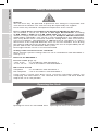
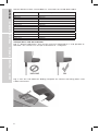
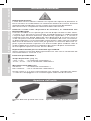
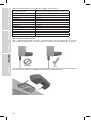
Opening the unit in its uninstalled state
Opening the Unit
Opening the unit in its installed state

5
ENGLISHFRANÇAIS
ESPAÑOL
ITALIANODANSK
DEUTSCH
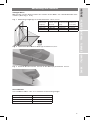
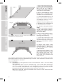
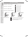
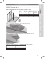
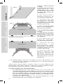
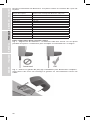
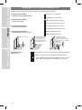
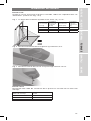
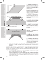
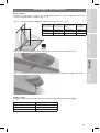
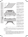
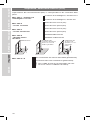
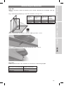
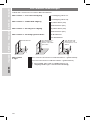
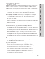
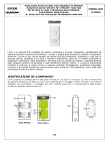
Straight Door
Mount the sensor above and in the centre of the door, on a hard vibration-free
surface. (See Fig. 1 to 5)
Fig. 1 Mounting height (h) must be between 1.8 to 3.0 m.
Fig. 2 Horizontal distance to door (a) maximum 0,5 m.
Fig. 3 Vertical distance from sensor to the door (b) maximum 10 cm.
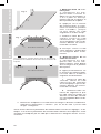
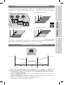
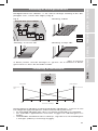
Curved Door
Curved door radius size as a function of mounting height
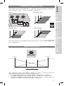
Mounting the Sensor
Motion zone
Presence zone
h
D1
W1
D2
Sensor
placement
height (h)
Depth
motion zone
(D1-D2)
Width
motion zone
(W1)
Depth
presence
zone (D2)
1800 mm 2040 mm 2460 mm 420 mm
2200 mm 2490 mm 3000 mm 510 mm
3000 mm 3400 mm 4100 mm 700 mm
Mounting height Curved door radius
2000 mm 1300 mm
2500 mm 1700 mm
3000 mm 2000 mm

Sensor distance from curved door as a function of curved door radius
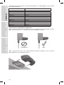
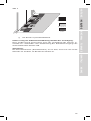
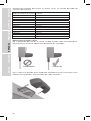
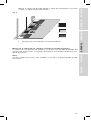
Straight Door and Curved Door
Fig. 4 Sensor alignment: The sensor must be mounted on a wall parallel to
the door. The sensor can accept a deviation of +3 degrees.
Fig. 5 Use the self-adhesive drilling template for correct mounting holes and
cable connection
6
Curved door radius Sensor mounting distance from door
800 mm 82 mm
900 mm 102 mm
1000 mm 122 mm
1100 mm 143 mm
1200 mm 167 mm
1300 mm 187 mm
1400 mm 210 mm
1500 mm 234 mm
1600 mm 258 mm
1700 mm 283 mm
1800 mm 308 mm
1900 mm 333 mm
2000 mm 359 mm
ENGLISHDEUTSCHFRANÇAISESPAÑOLITALIANODANSK

7
ENGLISHFRANÇAISESPAÑOLITALIANODANSK
DEUTSCH
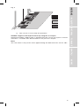
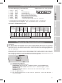
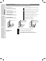
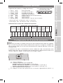
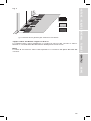
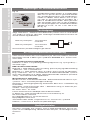
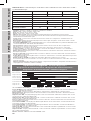
Pin assignment and colour code:
1 Pink [PK] Not connected
2 White [WH] Test input –*
3 Green [GN] Test input +*
4 Yellow [YE] Motion Output
5 Red [RD] Safe Output (presence zone)
6 Grey [GY] Common output
7 Blue [BU] – Supply
8 Brown [BN] + Supply 12 to 24 VAC/DC
* Active high: ON > 9 VAC/DC, OFF < 6 VAC/DC
Active low: ON < 6 VAC/DC, OFF > 9 VAC/DC
Door control system connection:
Electrical Connection
8 (BN)
1 (PK)
3 (GN)
6 (GY)
4 (YE)
5 (RD)
+ Supply 12 to 24 VAC/DC
Common Output
7 (BU)
2 (WH)
-
Safe Output (presence zone)
Motion Output
Test Input +
Test Input -
Not Connected
18
765432
Supply
Cable plug front view
Motion
(radar)
detector
input
(inside)
Motion
(radar)
detector
input
(outside)
Power
Supply
12-24 VAC
12-24 VDC
Power
Supply
12-24 VAC
12-24 VDC
Test
output
safety
sensor
(inside)
Test
output
safety
sensor
(outside)
Signal
input
safety
sensor
(inside)
Signal
input
safety
sensor
(outside)
-
-
+
+
Guardian 2 inside Guardian 2 outside
Door control system
brown (8)
brown (8)
Blue (7)
Blue (7)
Red (5)
Red (5)
Grey (6)
common
Grey (6)
common
Yellow (4)
Yellow (4)
++
Green (3)
Green (3)
White (2)
White (2)
N.C.Pink (1)
N.C.Pink (1)
--
ON
DIP
123456
MIN MAX
TEST HIGH
SAFE NO
MOTION NO
UNI-DIR.
LOW
NC
NC
BI-DIR.
5 MIN
1 MIN
30 SEC
10 SEC
SENSITIVITY PRESENCE
TIME
MIN MAX MIN MAXMIN MAX
MOTION AREA ADJUSTMMENT
CENTER
LEFT
RIGHT
TEACH-IN
TÜV NOT TÜV
Note:
Before switching on the unit, remove all objects from the detection area that
do not form part of the usual surroundings of the door. Also make sure that
nobody is within the motion area of the door during the teach-in phase.
The first time the sensor is powered up, all LEDs will form a running light. This
means that there is no valid presence zone stored into the sensor and the out-
puts are set at a safe state.
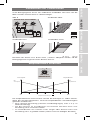
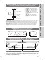
A: Close door.
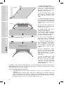
B: Place markers.
Straight door: Use 3 markers (see fig. 6)
Curved door inside: Use 7 markers (see fig. 7)
Curved door outside: Use 5 markers (see fig. 7.1)
C: Open the door fully.
D: Store presence zone into the sensor by following step 1 and 2.
Teaching the Presence Zone:
!

8
ENGLISHDEUTSCHFRANÇAISESPAÑOLITALIANODANSK
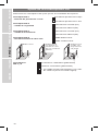
1. Teach the background
a. Place the white markers
like shown on the illustra-
tions (see fig. 6, 7 and 7.1),
to define the width and po-
sition of the entire door.
b. Press and hold the teach
button for 3 seconds until
all LEDs flash simultaneously.
c. Leave the motion area, all
LED’s will continue flashing
as long as there is move-
ment within the area.
d.When only the green LED
is flashing the background
is stored into the sensor.
2. Teach the presence
zone
a. Place the black markers
on top of the white markers,
defining the width and posi-
tion of the door.
b. Press teach button short-
ly. The 3 LEDs will start
flashing simultanously.
c. Leave the presence and
motion zone, all LEDs will
continue flashing as long as
there is movement within
the area.
d. When the LEDs stop
flashing and the green and
red LED lights is permantly
on, the safe zone is stored
in the sensor.
e. Remove the markers. The
green and red LED is on and
the sensor learn the ”nor-
mal” back-ground, (10, 30,
60 or 300 sec.) and the red
LED turn off.
Any failures during the teach-in procedure will cancel the settings and the
teach procedure must be repeated step a and b. This situation is shown with
the running light on all LEDs.
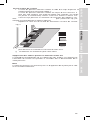
Test safe zone:
f. Verification of the presence zone must be done with a CA test body
DIN 18650-1
The presence zone can be verified using a test card. With advantage
you use a sheet of paper (i.e. A4 horisontally) as a test card. Please
use a testcard that provides the strongest possible contrast to the
background (the floor area) like black or white (see fig. 8).
Move the testcard from the motion zone into the safe zone and the
safe zone should react.
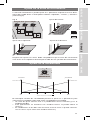
Fig. 6
Fig. 7.1
Motion zone
Motion zone
Precense zone
Fig. 7
Motion zone
Precense zone
Motion zone
The 2 marks shown on the two arrows must be placed
outside the moving door parts

9
ENGLISHFRANÇAIS
ESPAÑOL
ITALIANODANSK
DEUTSCH
Shadow suppression improvement by using the test input
Improved shadow suppression is performed if the sensor test input is activat-
ed within 3 seconds from deactivation of the presence output.
Note
The safe zone is only active when approaching the door from the sensor side.
Fig. 8
g. The sensor is now ready for operation.
Motion zone
Presence zone
Test card

10
ENGLISHDEUTSCHFRANÇAISESPAÑOLITALIANODANSK
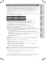
Set up the DIP-switches to match the door controller.
DIP-switch 1 - Sensor test input
DIP-switch 2 - Safety output
DIP-switch 3 - Motion output
DIP-switch 4 - Direction recognittion
DIP-switch 5 and 6
DIP-Switch Settings
Bi-directional Uni-directional
Doors remains
closed with cross
- traffic
Uni-directional
Opens only when
approaching the
door
Test input Active Low
Test input Active High
Normally closed (NC)
Normally open (NO)
Normally closed (NC)
Normally open (NO)
Bi-directional mode
Uni-directional mode
Not in accordance with DIN18650 (prEN16005)
In accordance with DIN18650 (prEN16005)
Not valid (red LED flashes and output
relays are in safe mode)
}

11
ENGLISHFRANÇAIS
ESPAÑOL
ITALIANODANSK
DEUTSCH
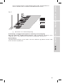
The motion zone can be blanked in 7 steps for all three directions using the 3
rotary switches “Left”, “Center” or “Right” (see fig. 9).
Fig. 9 Blanking center
Blanking left Blanking right
After adjusting
the zones it must be verified that the motion zone is active in the wanted area
by a ”walking test”.
Blanking of Motion Zone
ON
DIP
123456
MIN MAX
TEST HIGH
SAFE NO
MOTION NO
UNI-DIR.
LOW
NC
NC
BI-DIR.
5 MIN
1 MIN
30 SEC
10 SEC
SENSITIVITY PRESENCE
TIME
MIN MAX MIN MAXMIN MAX
MOTION AREA ADJUSTMMENT
CENTER
LEFT
RIGHT
TEACH-IN
TÜV NOT TÜV
The sensitivity rotary switch allows settings in 7 steps. In order to select the
right compromize between sensitivity and immunity.
• A normal setting would be 3-5 (Normal light condition) (4 is default).
• For indoor applications with light shadows, setting at 6-7 can be used.
• In outdoor conditions with strong light, rain or snow, a setting from 1-2
could be selected (strong light with heavy shadows).
Adjust Sensitivity
ON
DIP
123456
MIN MAX
TEST HIGH
SAFE NO
MOTION NO
UNI-DIR.
LOW
NC
NC
BI-DIR.
5 MIN
1 MIN
30 SEC
10 SEC
SENSITIVITY
PRESENCE
TIME
MIN MAX MIN MAXMIN MAX
MOTION AREA ADJUSTMMENT
CENTER
LEFT
RIGHT
TEACH-IN
TÜV NOT TÜV
1234567
SensitivityImmunity
Max Sensitivity
Recommended settings
Max Immunity
MaxMin
Motion zone
Presence zone

12
ENGLISHDEUTSCHFRANÇAISESPAÑOLITALIANODANSK
Fig. 10
Presence Time Settings
ON
DIP
123456
MIN MAX
TEST HIGH
SAFE NO
MOTION NO
UNI-DIR.
LOW
NC
NC
BI-DIR.
5 MIN
1 MIN
30 SEC
10 SEC
SENSITIVITY
PRESENCE
TIME
MIN MAX MIN MAXMIN MAX
MOTION AREA ADJUSTMMENT
CENTER
LEFT
RIGHT
TEACH-IN
TÜV NOT TÜV
Carlo Gavazzi Industri A/S, Over Hadstenvej 40, DK-8370 Hadsten, Denmark,
declare that the ESPE type 2 product Guardian 2 is in conformity with:
Low-Voltage Directive 2006/95/EC
EN60947-1: 2007 Low-voltage switchgear and control gear - General rules
EMC Directive 2004/108/EC
EN61326-1: 2006 Electrical equipment for measurement. Control and labora-
tory use – EMC requirements – Part 1: General Requirements
EN61000-3-1: 2008 Electrical equipment for measurement, control and
laboratory use - EMC requirements - Part 3-1: Immunity requirements for
safety-related systems and for equipment intended to perform safety-related
functions (functional safety) - General industrial applications
Machinery Directive 2006/42/EC
EN ISO 13849-1: 2008 Safety of machinery - Safety-related parts of control
systems - Part 1: General principles for design
DIN18650-1: 2005 Building hardware. Powered pedestrian doors.
Part 1: Product requirements and test methods
prEN16005: 2009 Powered pedestrian doors - Safety in use of power pedes-
trian doors - Requirements and test methods
EN 12978: 2003 + A1: 2009
Person authorised to compile the technical file:
K. Soerensen, Carlo Gavazzi Industri A/S, Over Hadstenvej 40,
DK-8370 Hadsten, Denmark
EC type examination No. 44 205 09 555114.
Notified body 0044
TÜV NORD CERT GmbH, Langemarckstr. 20, 45141 Essen, Germany
Hadsten, 3 June 2010, K. Soerensen (R&D Manager)
EC Declaration of Conformity
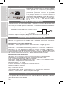
The sensor surface must be cleaned with soft cotton. Light soap water can be
used. No alcohol must be used as the frontglass can be miscoloured.
Maintenaince
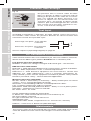
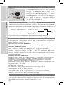
The presence time is used to “hold” the door
open if a person or object is present and not
moving in the presence zon. After the “Presence
time” has expired, the doors will close. If an
person or object has not moved within the
“Presence time”, the person or object will be
stored as part of the background. The “Present
time” can be set on the rotary switch for 10 sec,
30 sec, 1 min or 5 min. See fig. 10
According to DIN18650-1, EN12978, the door control system must have a
test function, which checks the presence detector for correct function and
connection at least once per door cycle.
Test Input
t
t
Active high, test pulse: 12-24 VAC/DC
0 VAC/DC
Active low, test pulse: 12-24 VAC/DC
0 VAC/DC
See test sequence (Operating Diagram) on page 66

13
ENGLISHFRANÇAISESPAÑOLITALIANODANSK
DEUTSCH
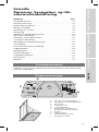
Optischer Sensor für
die Anwesenheits- und
Bewegungserfassung
INHALT Seite
Produktbeschreibung .................................. 13
Produktübersicht ...................................... 13
Sicherheitsvorschriften ................................. 14
Öffnen des Geräts ..................................... 14
Montage des Sensors .................................. 15
Elektrische Anschlüsse ................................. 17
Teachen der Anwesenheitszone .......................... 17
DIP-Schalterstellungen ................................. 20
Ausblenden von Teilbereichen der Bewegungszone .......... 21
Empfindlichkeit einstellen ............................... 21
Einstellungen der Verzögerungszeit der Anwesenheitszone ..... 22
Testeingang .......................................... 22
EG-Konformitätserklärung ............................... 22
Wartung ............................................. 22
Spezifikationen ....................................... 63
Betriebsdiagramm ..................................... 66
Schaltbild ............................................ 67
Abmessungen ........................................ 67
Bohrmaße ........................................... 67
Der Guardian 2 Sensor wurde speziell für automatische Schiebe- und
Rundschiebetüren im öffentlichen Bereich entwickelt
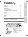
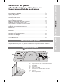
Produktbeschreibung
Produktübersicht
A
ON
DIP
123456
MIN MAX
TEST HIGH
SAFE NO
MOTION NO
UNI-DIR.
LOW
NC
NC
BI-DIR.
5 MIN
1 MIN
30 SEC
10 SEC
SENSITIVITY PRESENCE
TIME
MIN MAX MIN MAXMIN MAX
MOTION AREA ADJUSTMMENT
CENTER
LEFT
RIGHT
TEACH-IN
NOT COM-
PLIANT
COM-
PLIANT
GUARDIAN 2
A DIP-Schalter
B Verzögerungszeit Anwesenheitszone
C Empfindlichkeit
D Stecker
E LED-Anzeigen
F Drehschalter zum Ausblenden von
Teilbereichen in der Bewegungszone
G Kamera
H Teach-Taste
I Anwesenheitszone
J Bewegungszone
B
C
D
E
F
G
H
I
J

14
ENGLISHDEUTSCHFRANÇAISESPAÑOLITALIANODANSK
Sicherheitsvorschriften
Allgemein:
Das Gerät darf nur mit einer Schutzkleinspannung mit sicherer elektrischer
Trennung betrieben werden. Reparaturen dürfen nur vom Hersteller durchge-
führt werden. Berühren Sie keine elektrischen oder optischen Bauteile.
Einsatz als Schutzeinrichtung gemäß der europäischen Maschinenrichtlinie:
Der Guardian 2 Sensor hat die EG Baumusterprüfungen gemäß DIN
18650:2005§5.7.4, EN12978:2003 und weitere relevante Normen be-
standen und entspricht somit den Anforderungen der europäischen
Maschinenrichtlinie ( 2006/42/EG) Anhang 1. Der Sensor ist TÜV zertifiziert
und ist damit als alleinige Schutzeinrichtung an Schiebetoren zugelassen.
Die Risikobeurteilung, die korrekte Installation, die Berücksichtigung weit-
erer lokalen Vorschriften und Normen sowie die Einhaltung der geforderten
Erfassungsbereiche zur Absicherung von Gefahrenstellen während des Öffnen
und Schließens der Tür fällt in den Verantwortungsbereich des Installateurs
der automatischen Türanlage.
Es empfiehlt sich nicht, den Sensor direktem Licht auszusetzen.
Wichtige Informationen zur Norm DIN 18650-1
Einige Funktionen erlauben Einstellungen, die nicht mit DIN18650-1: 2005 §
5,7.2 übereinstimmen
Relevant für DIN18650-1
Verzögerungszeit Anwesenheitszone (Seite 18)
1 Min, 5 Min : gemäß DIN18650-1
10 Sek, 30 Sek : nicht gemäß DIN18650-1
DIP-Schalter 5 und 6
Übereinstimmend : gemäß DIN18650-1
Nicht übereinstimmend : nicht gemäß DIN18650-1
Sind die DIP Schalter auf übereinstimmend eingestellt und werden an-
schließend andere Einstellungen nicht nach DIN 18650-1 gewählt, blinkt die
rote LED und die Ausgangsrelais gehen in den sicheren Zustand
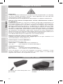
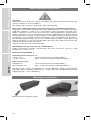
Öffnen der Einheit im nicht installier-
tem Zustand
Öffnen des Geräts
Öffnen der Einheit in installiertem
Zustand

Motion zone
Presence zone
h
D1
W1
D2
Anwesenheitszone
Bewegungszone
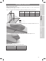
Schiebetüren
Den Sensor mittig über der Tür auf einer harten, vibrationsfreien Oberfläche
montieren. (siehe Abb. 1 bis 5)
Abb. 1 Montagehöhe (h) muss zwischen 1,80 und 3 m liegen.
Abb. 2 Horizontaler Abstand zur Tür (a) höchstens 0,50 m.
Abb. 3 Vertikaler Abstand vom Sensor zur Tür (b) höchstens 10 cm.
Rundschiebetüren
Radius der Rundschiebetüren in Abhängigkeit der Montagehöhe
15
ENGLISHFRANÇAISESPAÑOLITALIANODANSK
DEUTSCH
Montage des Sensors
Sensor-
Montage-
höhe (h)
Tiefe ewe-
gungszone
(D1-D2)
Breite ewe-
gungszone
(W1)
Tiefe
nwesen-
heitszone
(D2)
1800 mm 2040 mm 2460 mm 420 mm
2200 mm 2490 mm 3000 mm 510 mm
3000 mm 3400 mm 4100 mm 700 mm
Montagehöhe Radius der Rundschiebetür
2000 mm 1300 mm
2500 mm 1700 mm
3000 mm 2000 mm

16
ENGLISHDEUTSCHFRANÇAISESPAÑOLITALIANODANSK
Abb. 5 Benutzen Sie die selbstklebende Bohrschablone für korrekte
Montagelöcher und Kabelanschluss
FALSCH
Abstand zwischen Sensor und Rundschiebetür in Abhängigkeit vom Radius
der Rundschiebetür
Radius der Rundschiebetür Abstand zwischen Sensor und Rundschiebetür
800 mm 82 mm
900 mm 102 mm
1000 mm 122 mm
1100 mm 143 mm
1200 mm 167 mm
1300 mm 187 mm
1400 mm 210 mm
1500 mm 234 mm
1600 mm 258 mm
1700 mm 283 mm
1800 mm 308 mm
1900 mm 333 mm
2000 mm 359 mm
Schiebetüren und Rundschiebetüren
Abb. 4 Sensorausrichtung: Der Sensor muss parallel zur Tür montiert werden.
Eine Abweichung von + 3 Grad kann noch akzeptiert werden

Achtung:
Vor Einschalten der Einheit müssen alle Gegenstände, die nicht zur normalen
Umgebung der Tür gehören, aus dem Erfassungsbereich entfernt werden. Es
darf sich auch niemand während der Teach-in-Phase im Bewegungsbereich
der Tür aufhalten.
Wenn der Sensor zum ersten Mal eingeschaltet wird, bilden alle LED ein
Lauflicht, d.h. sie blinken kurz nacheinander auf und erlöschen dann wieder.
Das heißt, im Sensor ist keine gültige Anwesenheitszone abgespeichert und
die Ausgänge sind auf einen sicheren Zustand eingestellt.
A: Schließen Sie die Tür.
B: Platzieren der Markierungen.
Schiebetür: Benutzen Sie 3 Markierungen ( siehe Abbildung 6)
Rundschiebetür innen: Benutzen Sie 7 Markierungen ( siehe
Abbildung 7)
Rundschiebetür außen: Benutzen Sie 5 Markierungen ( siehe
Abbildung 7.1)
C: Die Tür ganz öffnen.
D: Die Anwesenheitszone in den Sensor speichern. Dazu die Schritte 1
und 2 befolgen.
17
ENGLISHFRANÇAISESPAÑOLITALIANODANSK
DEUTSCH
Anschlussbelegung und Farbcode:
1 Rosa [PK] NC
2 Weiß [WH] Testeingang –*
3 Grün [GN] Testeingang +*
4 Gelb [YE] Relais ( Bewegungszone)
5 Red [RD] Relais (Anwesenheitszone)
6 Grau [GY] Gemeinsamer Relaiskontakt
7 Blau [BU] – Betriebsspannung
8 Braun [BN] + Betriebsspannung 12 bis 24 V AC/DC
* Testeingang mit HIGH Signal: ON > 9 VAC/DC, OFF < 6 VAC/DC
Testeingang mit Low Signal: ON < 6 VAC/DC, OFF > 9 VAC/DC
Anschluss Türkontrollsystem:
Elektrische Anschlüsse
8 (BN)
1 (PK)
3 (GN)
6 (GY)
4 (YE)
5 (RD)
+ Supply 12 to 24 VAC/DC
Common Output
7 (BU)
2 (WH)
-
Safe Output (presence zone)
Motion Output
Test Input +
Test Input -
Not Connected
18
765432
Supply
Kabelstecker von vorn gesehen
Eingang
Bewe-
gungs-
(Radar-)
melder
(innen)
Betriebs-
spannung
12-24 VAC
12-24 VDC
Test-
ausgang
Sicher-
heits-
sensor
(innen)
Signal-
eingang
Sicher-
heits-
sensor
(innen)
-
-
+
+
Guardian 2 innen Guardian 2 außen
Tür Controller
Braun (8)
Braun (8)
Blau (7)
Blau (7)
Rot (5)
Rot (5)
Grau (6)
gemeinsam
Grey (6)
gemeinsam
Gelb (4)
Gelb (4)
++
Grün (3)
Grün (3)
Weiß (2)
Weiß (2)
N.C.Rosa (1)
N.C.Rosa (1)
--
Betriebs-
spannung
12-24 VAC
12-24 VDC
Signal-
eingang
Sicher-
heits-
sensor
(außen)
Eingang
Bewe-
gungs-
(Radar-)
melder
(außen)
Test-
ausgang
Sicher-
heits-
sensor
(außen)
ON
DIP
123456
MIN MAX
TEST HIGH
SAFE NO
MOTION NO
UNI-DIR.
LOW
NC
NC
BI-DIR.
5 MIN
1 MIN
30 SEC
10 SEC
SENSITIVITY PRESENCE
TIME
MIN MAX MIN MAXMIN MAX
MOTION AREA ADJUSTMMENT
CENTER
LEFT
RIGHT
TEACH-IN
TÜV NOT TÜV
Teachen der Anwesenheitszone:
!

18
1. Den Hintergrund
teachen
a. Platzieren Sie die weißen
Markierungen wie in den
Abbildungen 6 oder 7 oder
7.1 beschrieben. Damit wird
die Breite und Position der
Tür eingelernt.
b. Die Teach-Taste 3
Sekunden lang drücken, bis
alle LED gleichzeitig blinken.
c. Verlassen Sie die
Bewegungszone. Solange
Bewegungen in der Zone
stattfinden blinken alle LED
weiterhin gleichzeitig
d. Wenn nur die grüne LED
blinkt, ist der Hintergrund in
den Sensor gespeichert.
2. Die Anwesenheitszone
teachen
a. Legen Sie die schwarzen
Markierungen auf die weißen
Markierungen. Damit wird
die Breite und Position der
Tür eingelernt.
b. Die Teach-Taste kurz
drücken Die 3 LED begin-
nen gleichzeitig zu blinken.
c. Verlassen Sie die
Bewegungs- und
Anwesenheitszone. Solange
Bewegungen in den Zonen
stattfinden blinken alle LED
weiterhin gleichzeitig.
d. Wenn die LED auf-
hören zu blinken und
die grüne und rote LED
dauerhaft leuchtet ist
die Anwesenheitszone
(Sicherheitszone) im Sensor
gespeichert.
e. Die Markierungen entfernen. Die grüne und rote LED leuchten, der
Sensor lernt den „normalen“ Hintergrund (10, 30, 60 oder 300 Sek.)
und die rote LED erlischt.
Jeder Fehler während des Teachens führt zu einem Abbruch der
Einstellungen, das Teachen (Schritt a. und b.) muss dann wiederholt werden.
Diese Situation wird durch Lauflicht an allen LED angezeigt.
Test Anwesenheitszone ( Sicherheitszone):
f. Die Überprüfung der Anwesenheitszone muss mit einem CA
Testkörper gemäß DIN 18650 erfolgen. Für einen ersten einfachen Test
kann die Überprüfung der Anwesenheitszone auch mit einem DINA4
Blatt als Testobjekt erfolgen.. Die Farbe des Blatts soll den größtmögli-
chen Kontrast zum Hintergrund ( Boden ) haben. Zum Beispiel schwarz
zu weiß ( siehe Abbildung 8 ).
Bewegen Sie das Testobjekt von der Bewegungszone in die
Anwesenheitszone. Der Ausgang muss reagieren.
Abb. 6
Abb. 7.1
Bewegungszone
Bewegungszone
Präsenzzone
Abb. 7
Bewegungszone
Präsenzzone
Bewegungszone
The 2 marks shown on the two arrows must be placed
outside the moving door parts
ENGLISHDEUTSCHFRANÇAISESPAÑOLITALIANODANSK

19
ENGLISHFRANÇAISESPAÑOLITALIANODANSK
DEUTSCH
Verbesserung der Schattenunterdrückung mit Hilfe des Testeingang.
Diese Verbesserung wird erreicht wenn der Testeingang des Sensors in-
nerhalb von 3 Sekunden nach Deaktivierung des Sicherheitsausgangs der
Anwesenheitszone aktiviert wird.
Anmerkung:
Die Anwesenheitszone ( Sicherheitszone ) ist nur aktiv, wenn man sich zu der
Seite der Tür annähert, wo der Sensor montiert ist.
Abb. 8
g. Der Sensor ist jetzt betriebsbereit.
Motion zone
Presence zone
Test card
Anwesenheitszone
Bewegungszone
Testkarte

20
ENGLISHDEUTSCHFRANÇAISESPAÑOLITALIANODANSK
Konfigurieren der DIP-Schalter passend zur Türsteuerung.
DIP-Schalter 1
- Sensor Testeingang
DIP-Schalter 2
- Sicherheits-Ausgang
(Anwesenheit)
DIP-Schalter 3
- Bewegungs-Ausgang
DIP-Schalter 4
- Richtungserkennung
DIP-Schalter
5 und 6
DIP-Schalterstellungen
Bidirektional Unidirektional
Türen bleiben
bei Querverkehr
geschlossen
Unidirektional
Öffnen sich nur,
wenn sich jemand
der Tür nähert
Test Eingang Aktiv bei LOW signal
Test Eingang Aktiv bei HIGH signal
Normalerweise geschlossen (NG)
Normalerweise geöffnet (NO)
Normalerweise geschlossen (NG)
Normalerweise geöffnet (NO)
Bidirektionaler Modus
Unidirektionaler Modus
Nicht nach DIN18650 (prEN16005)
Nach DIN18650 (prEN16005)
Nicht gültig (rote LED blinkt und
Ausgangsrelais stehen im Safe-Modus)
}
La pagina si sta caricando...
La pagina si sta caricando...
La pagina si sta caricando...
La pagina si sta caricando...
La pagina si sta caricando...
La pagina si sta caricando...
La pagina si sta caricando...
La pagina si sta caricando...
La pagina si sta caricando...
La pagina si sta caricando...
La pagina si sta caricando...
La pagina si sta caricando...
La pagina si sta caricando...
La pagina si sta caricando...
La pagina si sta caricando...
La pagina si sta caricando...
La pagina si sta caricando...
La pagina si sta caricando...
La pagina si sta caricando...
La pagina si sta caricando...
La pagina si sta caricando...
La pagina si sta caricando...
La pagina si sta caricando...
La pagina si sta caricando...
La pagina si sta caricando...
La pagina si sta caricando...
La pagina si sta caricando...
La pagina si sta caricando...
La pagina si sta caricando...
La pagina si sta caricando...
La pagina si sta caricando...
La pagina si sta caricando...
La pagina si sta caricando...
La pagina si sta caricando...
La pagina si sta caricando...
La pagina si sta caricando...
La pagina si sta caricando...
La pagina si sta caricando...
La pagina si sta caricando...
La pagina si sta caricando...
La pagina si sta caricando...
La pagina si sta caricando...
La pagina si sta caricando...
La pagina si sta caricando...
La pagina si sta caricando...
La pagina si sta caricando...
La pagina si sta caricando...
La pagina si sta caricando...
-
 1
1
-
 2
2
-
 3
3
-
 4
4
-
 5
5
-
 6
6
-
 7
7
-
 8
8
-
 9
9
-
 10
10
-
 11
11
-
 12
12
-
 13
13
-
 14
14
-
 15
15
-
 16
16
-
 17
17
-
 18
18
-
 19
19
-
 20
20
-
 21
21
-
 22
22
-
 23
23
-
 24
24
-
 25
25
-
 26
26
-
 27
27
-
 28
28
-
 29
29
-
 30
30
-
 31
31
-
 32
32
-
 33
33
-
 34
34
-
 35
35
-
 36
36
-
 37
37
-
 38
38
-
 39
39
-
 40
40
-
 41
41
-
 42
42
-
 43
43
-
 44
44
-
 45
45
-
 46
46
-
 47
47
-
 48
48
-
 49
49
-
 50
50
-
 51
51
-
 52
52
-
 53
53
-
 54
54
-
 55
55
-
 56
56
-
 57
57
-
 58
58
-
 59
59
-
 60
60
-
 61
61
-
 62
62
-
 63
63
-
 64
64
-
 65
65
-
 66
66
-
 67
67
-
 68
68


in altre lingue
Documenti correlati
-
CARLO GAVAZZI LDP2PA2DU24 Manuale del proprietario
-
-
-
-
CARLO GAVAZZI PD112CNB25BPM1 Manuale utente
-
-
CARLO GAVAZZI CA30CLN12MV10M Manuale utente
-
-
CARLO GAVAZZI UA18CAD04NKTI Manuale utente
-
Altri documenti
-
CAME MR8700 Manuale utente
-
 quiko QK-RADAR Manuale utente
-
 Elkron EIR500 Guida d'installazione
-
-
Wine Guardian SS018 Ductless Split System Wine Cellar Cooling Unit Manuale del proprietario
-
 quiko QK-RADAROMNI Manuale utente
-
-
Genius SPRINT11SW Istruzioni per l'uso
-
STEINEL HF 180 Information
-
Nice Automation Signo Manuale del proprietario


