CD Automation Temperature Controller Revo TC 2ph Manuale utente
- Categoria
- Misurazione, test
- Tipo
- Manuale utente

CD Automation S.r.l.
Via Picasso 34/36 - 20025 – Legnano (MI) – ITALY
Tel +39 0331 577479 – Fax +39 0331 579479
E-Mail: info@cdautomation.com - WEB: www.cdautomation.com
Revo TC 2ph
Temperature Controller
Part 1
USER’S MANUAL
Rev. 2/2016
00001

CD Automation srl
pag. 2 di 122

CD Automation srl
pag. 3 di 122
1 Important warnings for safety ________________________________________ 8
2 Note ____________________________________________________________ 9
3 Identification and Order Code _______________________________________ 10
3.1 Identification of the unit ______________________________________________ 10
3.2 Order Code ________________________________________________________ 11
4 Technical Specifications ____________________________________________ 12
4.1 Environmental installation conditions ____________________________________ 12
4.2 Derating Curve _____________________________________________________ 12
5 Installation ______________________________________________________ 12
5.1 Dimensions and Weight ______________________________________________ 13
5.2 Fixing holes ________________________________________________________ 13
6 Wiring instructions ________________________________________________ 14
6.1 Out Terminal (Terminal block M1) ______________________________________ 14
6.2 Supply Terminal (Terminal block M2) ____________________________________ 14
6.3 Communication Terminal RS485 (Terminal block M3) _______________________ 14
6.4 Input Terminal (Terminal block M4) _____________________________________ 14
6.5 Connection Diagram _________________________________________________ 15
6.6 Access to Ln – Tn terminal Screw _______________________________________ 17
7 TU Module Basic __________________________________________________ 18
8 Control Panel ____________________________________________________ 19
9 Display _________________________________________________________ 21
9.1 Indicators _________________________________________________________ 22
9.2 Possible outputs REVO TCM (Temperature Controller only) ___________________ 22
9.3 Possible outputs REVO TC (SSR + Temperature Controller) __________________ 22
10 Operative Mode __________________________________________________ 23
11 Functions ______________________________________________________ 24
11.1 Special Functions __________________________________________________ 24
11.2 Manual Mode ______________________________________________________ 25
11.3 Showing break-down alarm __________________________________________ 25
11.4 Showing leakage alarm _____________________________________________ 26
11.5 Showing loop-break alarm ___________________________________________ 26
12 Function “Soft start” ______________________________________________ 26
13 Detection of malfunctions __________________________________________ 27
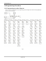
14 Programming Procedure ___________________________________________ 28
14.1 Programming procedure Diagram ______________________________________ 28
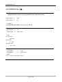
14.2 SET POINT Group (
SP
) _____________________________________________ 29
14.3 ALARM Group (
AL
) ________________________________________________ 31
14.3.1 Alarm Function _________________________________________________________________ 33
14.3.2 Alarm Hysteresis _______________________________________________________________ 37

CD Automation srl
pag. 4 di 122
14.3.3 Alarm Out _____________________________________________________________________ 37
Action of alarm output. ___________________________________________________________ 38
14.3.5 Resetting of an Alarm ____________________________________________________________ 38
14.3.6 Alarm mask ___________________________________________________________________ 39
14.4 Control Group (
Cntr
) _____________________________________________ 40
14.5 OUT Group(
Out
) _________________________________________________ 43
14.6 Group
EHT
(Functions setted also from input1 and input2) __________________ 45
14.7 Group
DEF
(default of run time Loading) ________________________________ 47
14.8 Group
PAL1
(Pallet 1 control parameters) _______________________________ 47
14.9 Group
PAL2
(Pallet 2 control parameters) _______________________________ 49
14.10 Group
PAL3
(Pallet 3 control parameters) ______________________________ 49
15 SELF-TUNING Algorithms __________________________________________ 52
15.1 PreTune __________________________________________________________ 52
15.2 SelfTune _________________________________________________________ 53
16 Serial RS485 and USB communication interface _________________________ 54
17 Configuration Mode ______________________________________________ 55
17.1 Description _______________________________________________________ 55
17.2 Configuration procedure diagram ______________________________________ 56
17.3 Group INPUT (
inP
) ________________________________________________ 58
17.4 Group I/O (
io
) ___________________________________________________ 60
17.4.1 Out 1 ________________________________________________________________________ 60
17.4.2 OUT 2 ________________________________________________________________________ 61
17.4.3 OUT 3 or Di 1 __________________________________________________________________ 62
17.4.4 Out 4 ________________________________________________________________________ 64
17.4.5 General _______________________________________________________________________ 65
17.5 ALARM Group(
AL
) _________________________________________________ 66
17.5.1 Alarm 1 _______________________________________________________________________ 66
17.5.2 Alarm 2 _______________________________________________________________________ 67
17.5.3 Alarm 3 _______________________________________________________________________ 68
17.6 Heating Break-Down Group (
Hbdu
) __________________________________ 69
17.7 Loop break Group(
LbAL
) ___________________________________________ 69
17.8 SELFTUNE Group(
tunE
)____________________________________________ 70
17.9 SOFT START Group (
SoF
t ) __________________________________________ 71
17.10 Gruppo PARAMETRI VARI (
niSC
) ___________________________________ 71
17.11 RS485 Group (
r485
) _____________________________________________ 74
17.12 Default Configuratiov Group (
deF
) __________________________________ 75
17.13 Notes ___________________________________________________________ 76
18 Serial communications ____________________________________________ 77

CD Automation srl
pag. 5 di 122
18.1 introduction to Modbus Protocol _______________________________________ 77
18.2 TABLE 0 _________________________________________________________ 79
18.3 WORDS ADDRESS __________________________________________________ 79
18.4 BITS ____________________________________________________________ 88
18.5 TABLE 1 (WEST 6600) ______________________________________________ 89
18.6 Status Table (Word 7) ______________________________________________ 90
19 Default Parameter Loading _________________________________________ 92
19.1 User procedure ____________________________________________________ 92
19.2 Loading Default operative parameter ___________________________________ 92
19.3 Default configuration parameter Loading ________________________________ 93
19.3.1 European table _________________________________________________________________ 94
19.3.2 Americana table ________________________________________________________________ 97
20 Calibration Procedure ____________________________________________ 102
20.1 Description ______________________________________________________ 102
20.2 Guidelines for calibration ___________________________________________ 102
20.3 Calibration from keypad ____________________________________________ 103
20.3.1 TC and linear input calibration ____________________________________________________ 104
20.3.2 Cold Junction Calibration ________________________________________________________ 105
20.3.3 RTD Input Calibration ___________________________________________________________ 106
20.3.4 Input Calibration mA ___________________________________________________________ 107
20.3.5 Input 10 V Calibration __________________________________________________________ 108
20.3.6 Current transformer Input calibration _______________________________________________ 109
20.4 Calibration from serial _____________________________________________ 110
20.4.1 Input TC and LINEAR Input calibration ______________________________________________ 110
20.4.2 Cold Junction Calibration ________________________________________________________ 111
20.4.3 RTD Input Calibration ___________________________________________________________ 111
20.4.4 Input Calibration mA ___________________________________________________________ 112
20.4.5 Input 10 V Calibration __________________________________________________________ 113
20.4.6 Calibrazione Input Trasformatore Amperometrico _____________________________________ 114
20.5 Caricamento valori di calibrazione di default ____________________________ 114
21 Tables: _______________________________________________________ 115
21.1 Table 1 _________________________________________________________ 115
21.2 Table 2 _________________________________________________________ 115
22 Test Hardware via seriale _________________________________________ 116
22.1 Display Test _____________________________________________________ 117
22.2 Led Test ________________________________________________________ 117
22.3 FUNC key Test ___________________________________________________ 117
22.4 MAN Key Test ____________________________________________________ 117
22.5 UP key Test ______________________________________________________ 117
22.6 DOWN key Test ___________________________________________________ 117
22.7 EEPROM Test _____________________________________________________ 117

CD Automation srl
pag. 6 di 122
22.8 Relè 1 Test ______________________________________________________ 117
22.9 Relè 2 Test ______________________________________________________ 117
22.10 Relè 3 Test _____________________________________________________ 118
22.11 Relè 4 Test _____________________________________________________ 118
22.12 Out 4 mA Test ___________________________________________________ 118
22.13 Out 20 mA Test __________________________________________________ 118
22.14 Input 1 Test ____________________________________________________ 118
22.15 Input 2 Test ____________________________________________________ 118
22.16 10 mV measure Test ______________________________________________ 119
22.17 60 mV measure Test ______________________________________________ 119
22.18 4 mA measure Test _______________________________________________ 119
22.19 20 mA measure Test ______________________________________________ 119
22.20 0 ohm measure Test ______________________________________________ 120
22.21 300 ohm measure Test ____________________________________________ 120
22.22 1 V measure Test ________________________________________________ 120
22.23 10 V measure Test _______________________________________________ 120
22.24 RJ Test ________________________________________________________ 121
22.25 TA 5 mA measure Test ____________________________________________ 121
22.26 TA 50 mA measure Test ___________________________________________ 121

CD Automation srl
pag. 7 di 122
CD Automation
s.r.l.
Controllers, Drives & Automation
Via Picasso, 34/36 - 20025 Legnano (MI)- Italia
P.I. 08925720156 -Tel. (0331) 577479 - Fax (0331) 579479
Internet : www.cdautomation.com - E-MAIL: info@cdautomation.com
Dichiarazione di Conformità
Declaration of Conformity
PRODUTTORE:
PRODUCT MANUFACTURER: CD Automation S.R.L.
INDIRIZZO:
ADDRESS: Via Pablo Picasso 34//36
20025 Legnano (Mi)
Italia
Dichiara che il prodotto:
Declare that the product:
Revo TC
SODDISFA I REQUISITI DELLA NORMA :
Specifica di sicurezza EN60947-1 :2008
EN60947-4-3:2001
Specifica sulle emissioni EN60947-4-3:2000
Specifica sulle Immunità EN60947-4-3:2000
FULFILS THE REQUIREMENTS OF THE STANDARD:
Electrical safety Standard EN60947-1 :2008
EN60947-4-3:2001
Generic Emission standard EN60947-4-3:2000
Generic Immunity standard EN60947-4-3:2000
CDAutomation dichiara che I prodotti sopra menzionati sono conformi alla direttiva
CDAutomation declares that The products above mentioned they am conforming to the directive
EMC 2004/108/CEE e alla direttiva Bassa Tensione (low Voltage) 2006/95/CEE
DESCIZIONE DEL PRODOTTO: Unità di controllo potenza elettrica
PRODUCT DESCRIPTION: Elettric power controll
UTILIZZO: Controllo processi termici
SCOPE OF APPLICATION: Thermal controll process
Data di emissione: 20/04/2010 Amministratore Unico e
Issued on: 20/04/2010 Legale Rappresentante
Claudio Brizzi

CD Automation srl
pag. 8 di 122
1 Important warnings for safety
This chapter contains important information for the safety. The not observance of these instructions may
result in serious personal injury or death and can cause serious damages to the Thyristor unit and to the
components system included.
The installation should be performed by qualified persons.
The Thyristor unit are integral part of industrial equipments. When it is supply, the
Thyristor unit is subject to dangerous tensions.
• Don't remove the protection Cover.
• Don't use these unit in aerospace applications and/ or nuclear.
The nominal current corresponds to use at temperature not superior to 45°C.
• The Thyristor unit must be mounted in vertical position and without obstruction above
and below to allow a good flow ventilation.
• The hot air of one thyristor unit must not invest the unit positioned above.
• For side by side placed leave a space of 15mm between the unit.
A suitable device must ensure that the unit can be electrically isolated from the supply, this
allows the qualified people to work in safety.
Protection (Protection, Protezione)
The unit have IP20 protection rating as defined by the specific international. Is necessary
consider the place of installation.
Earth (Terre, Messa a terra)
For safety, the Thyristor unit with isolated heat-sink must be connected to earth.
Earth impedance should be correspondent to local earth regulation. Periodically the earth
efficiency should be inspected.
Electronic supply (Alimentation électronique, Alimentazione elettronica)
The electronic circuit of the Thyristor unit must be supplied by dedicated voltage for all
electronic circuits and not in parallel with coil contactors, solenoids and other.
It's recommended to use a shielded transformer.
Electric Shock Hazard (Risque de choque électrique, Rischi di scosse elettriche)
When the Thyristor unit is energized, after the power supply is shut off, wait least a minute
for allow the discharge of the internal capacitors where there is a dangerous tension. Before
working, make sure that:
• Only authorized personnel must perform maintenance, inspection, and replacement
operations.
• The authorized personnel must read this manual before to have access to the unit.
• Unqualified People don't perform jobs on the same unit or in the immediate vicinities.

CD Automation srl
pag. 9 di 122
Important warnings (Attention, Avvertenze importanti)
During the operations with units under tension, local regulations regarding electrical
installation should be rigidly observed:
• Respect the internal safety rules.
• Don't bend components to maintain insulation distances.
• Protect the units from high temperature humidity and vibrations.
• Don't touch components to prevent electrostatic discharges on them.
• Verify that the size is in line with real needs.
• To measure voltage current etc. on unit, remove rings and other jewels from fingers
and hands.
• Authorized personnel that work on thyristor unit under power supply voltage must be
on insulated board
This listing does not represent a complete enumeration of all necessary safety cautions.
Electromagnetic compatibility
(Compatibilità électromagnétique, Compatibilità elettromagnetica)
Our thyristor units have an excellent immunity to electromagnetic interferences if all
suggestions contained in this manual are respected. In respect to a good Engineering
practice, all inductive loads like solenoids contactor coils should have a filter in parallel.
Emissions (Emission, Emissioni)
All solid-state power controllers emit a certain amount of radio-frequency energy because
of the fast switching of the power devices.
The CD Automation’s Thyristor unit are in accord with the EMC norms, CE mark.
In most installations, near by electronic systems will experience no difficulty with
interference. If very sensitive electronic measuring equipment or low-frequency radio
receivers are to be used near the unit, some special precautions may be required. These
may include the installation of a line supply filter and the use of screened (shielded) output
cable to the load.
2
Note
Warning: This icon is present in all the operational procedures where the Improper
operation may result in serious personal injury or death
Caution: This icon is present in all the operational procedures where the Improper
operation can cause damage for the unit.
CD Automation reserves the right to modify the own products and this manual without any
advise.

CD Automation srl
pag. 10 di 122
3 Identification and Order Code
3.1
Identification of the unit
Attenzione: Prima dell’installazione, assicurarsi che
l'unità a thyristor non abbia subito danni durante il
trasporto. In caso di danneggiamento, notificarlo
immediatamente al corriere..
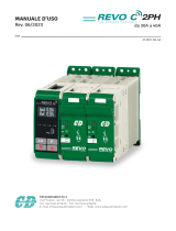
The identification's label give all the information regarding the factory settings of the Thyristor
unit, this label is on the unit, like represented in figure.
Verify that the product is the same thing as ordered.

CD Automation srl
pag. 11 di 122
3.2
Order Code

CD Automation srl
pag. 12 di 122
4 Technical Specifications
4.1
Environmental installation conditions
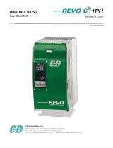
Ambient temperature 0-40°C at nominal current. Over 40°C use the
derating curve.
Storage temperature -25°C a 70°C
Installation place
Don’t install at direct sun light, where there
are conductive dust, corrosive gas, vibration or
water and also in salty environmental.
Altitude
Up to 1000 meter over sea level. For higher
altitude reduce the nominal current of 2% for
each 100m over 1000m
Humidity From 5 to 95% without condense and ice
Pollution Level Up to 2nd Level ref. IEC 60947-1 6.1.3.2
4.2
Derating Curve
5
Installation
Before to install, make sure that the Thyristor
unit have not damages.
If the product has a fault, please contact the
dealer from which you purchased the product.
Verify that the product is the same thing as
ordered.
The Thyristor unit must be always mounted in
vertical position to improve air cooling on
heat-sink.
Maintain the minimum distances in vertical
and in horizontal as represented.
When more unit has mounted inside the
cabinet maintain the air circulation like
represented in figure.
Sometimes is necessary installing a fan to
have better air circulation.

CD Automation srl
pag. 13 di 122
5.1
Dimensions and Weight
REVO M 2PH
Size W(mm) H(mm) D(mm) Weight (kg)
2PH 108 121 185 1,76
5.2
Fixing holes

CD Automation srl
pag. 14 di 122
6 Wiring instructions
Warning: Before connecting or disconnecting the unit check that power and
control cables are isolated from voltage sources.
6.1
Out Terminal (Terminal block M1)
Terminal Description SSR Out DI Input Relay Out
Digital
Input/Output
1 OUT4 SSR– DI2 C DI/O 2
2 OUT4 SSR+ DI2 NO DI/O 2
3 OUT3 SSR– DI1 C DI/O 1
4 OUT3 SSR+ DI1 NO DI/O 1
5 OUT2 SSR– _ C
_
6 OUT2 SSR+ _ NO
_
7 TA _ _
_ _
8 TA _ _
_ _
9 OUT1 SSR– _ C
_
10 OUT1 SSR+ _ NO
_
“-“ = Not available
6.2
Supply Terminal (Terminal block M2)
Terminal
Description
11 Supply 24Vdc/ac
12 Supply 24Vdc/ac
6.3
Communication Terminal RS485 (Terminal block M3)
Terminal
Description
A+ RS485 A +
B- RS485 B -
6.4
Input Terminal (Terminal block M4)
Terminal
Description
13 PT100
14 TC+ PT100 V+ mA+
15 TC- Compensazione V- mA-

CD Automation srl
pag. 15 di 122
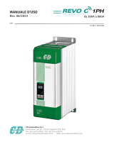
6.5
Connection Diagram
Revo TC Basic:
Revo TC with flat wiring system Option:

CD Automation srl
pag. 16 di 122
Caution: this procedure must be performed only by qualified persons.
* See Out terminal chapter for more informations
*
2
Only with flat wiring system Option: connect with proper cable (RJ45 Cat 5E Patch Cable UTP)
as shown:

CD Automation srl
pag. 17 di 122
The cable supplyed by CD Automation are
Lenght Code
0,15 m
ICOC U5EB-001
0,3 m
ICOC U5EB-003-GREE
0,5 m ICOC U5EB-005-GREE
1 m ICOC U5EB-010-GREE
2 m ICOC U5EB-020-GREE
3 m ICOC U5EB-030-GREE
5 m
ICOC U5EB-050-GREE
7,5 m
ICOC U5EB-075-GREE
10 m
ICOC U5EB-100-GREE
15 m
ICOC U5EB-150-GREE
6.6
Access to Ln – Tn terminal Screw

CD Automation srl
pag. 18 di 122
7 TU Module Basic
Revo TU is a termination unit that provides the power supply and RS485 comms (modbus RTU) for up to
max 10 REVO TC units.
Terminal block M1
Terminal
Description
1 RS485 B -
2 RS485 A +
3 Global Output
4 Global Output
Terminal block M2
Terminal
Description
5 Not Used
6 Supply 24Vdc/ac
7 Supply 24Vdc/ac
Terminal Block M3 for flat wiring system

CD Automation srl
pag. 19 di 122
8 Control Panel
The keyboard is composed of four push button properly identified and protected: depending on the status
of each device button assumes a specific function, as described below.
Text or Combination
Description of function associated
▲
Configuration and operational
Skip to next parameter or group
Configuration and ongoing operational and edit
Increases the value of the parameter currently displayed
Operating with manual output
Increases the value of control output
Automatic Operation
If enabled, after 3 sec ill set point increases
▼
Configuration and operational
Skip to the previous group or parameter
Configuration and ongoing operational and edit
Decreases the value of the parameter currently displayed
Operating with manual output
Decreases the value of control output
Automatic Operation
If enabled, after 3 sec the set point decreases
FUNC
Operating
Release
Avoid the Change of the value displayed through the upper LCD.
Accept the changed value
Operating
T> 3 sec
Special Views: load current, leakage current, heating power, the cooling power, firmware version.
Configuration
Avoid the Change of the value of information displayed through the upper LCD.
Accept the changed value
MAN
Operating
Exit the current group
While editing a parameter abort editing
Operating
T> 3 sec
Set automatic or manual control mode
Configuration
Exit the current group
While editing a parameter abort editing

CD Automation srl
pag. 20 di 122
(▲/▼) + MAN
Operating
during numeric editing
Reaches the max / min set for the actual parameter
Configuration
during numeric editing
Reaches the max / min set for the current parameter
FUNC + MA N
Operating
t > 3 sec.
Input in configuration mode
▲ + FUN C
Operating
t > 3 sec.
Lamp test
▼ + FUN C
Operating
t > 3 sec.
Input in calibration mode
▼ + MAN
Operativo
Show on
the display below the load current or SetPoint
La pagina si sta caricando...
La pagina si sta caricando...
La pagina si sta caricando...
La pagina si sta caricando...
La pagina si sta caricando...
La pagina si sta caricando...
La pagina si sta caricando...
La pagina si sta caricando...
La pagina si sta caricando...
La pagina si sta caricando...
La pagina si sta caricando...
La pagina si sta caricando...
La pagina si sta caricando...
La pagina si sta caricando...
La pagina si sta caricando...
La pagina si sta caricando...
La pagina si sta caricando...
La pagina si sta caricando...
La pagina si sta caricando...
La pagina si sta caricando...
La pagina si sta caricando...
La pagina si sta caricando...
La pagina si sta caricando...
La pagina si sta caricando...
La pagina si sta caricando...
La pagina si sta caricando...
La pagina si sta caricando...
La pagina si sta caricando...
La pagina si sta caricando...
La pagina si sta caricando...
-
 1
1
-
 2
2
-
 3
3
-
 4
4
-
 5
5
-
 6
6
-
 7
7
-
 8
8
-
 9
9
-
 10
10
-
 11
11
-
 12
12
-
 13
13
-
 14
14
-
 15
15
-
 16
16
-
 17
17
-
 18
18
-
 19
19
-
 20
20
-
 21
21
-
 22
22
-
 23
23
-
 24
24
-
 25
25
-
 26
26
-
 27
27
-
 28
28
-
 29
29
-
 30
30
-
 31
31
-
 32
32
-
 33
33
-
 34
34
-
 35
35
-
 36
36
-
 37
37
-
 38
38
-
 39
39
-
 40
40
-
 41
41
-
 42
42
-
 43
43
-
 44
44
-
 45
45
-
 46
46
-
 47
47
-
 48
48
-
 49
49
-
 50
50


CD Automation Temperature Controller Revo TC 2ph Manuale utente
- Categoria
- Misurazione, test
- Tipo
- Manuale utente
in altre lingue
Documenti correlati
-
 CD Automation Termoregolatore Revo TC 1PH Manuale utente
-
 CD Automation REVO S 2PH Manuale del proprietario
-
 CD Automation REVO C 2PH Manuale del proprietario
-
 CD Automation REVO C 1PH Manuale del proprietario
-
 CD Automation REVO C 1PH Manuale del proprietario
-
 CD Automation Revo M 2PH Manuale del proprietario
-
 CD Automation REVEX 2PH Manuale del proprietario
-
 CD Automation REVEX 3PH Manuale del proprietario
-
 CD Automation REVO CL Manuale del proprietario
-
 CD Automation REVEX 1PH Manuale del proprietario


