
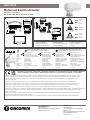
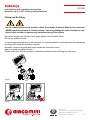
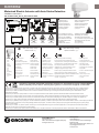
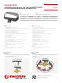
K281X012
Motorised Electric Actuator
P/N 14-88410-630 Rev. A Issue Date 07 2022
Installation Instructions
GIACOMINI S.p.A.
Via per Alzo 39
28017 San Maurizio d’Opaglio (NO) Italy
www.giacomini.com
UK Importer
GIACOMINI U.K.
Unit 2, Goodrich Close, Westerleigh
Business Park
Yate, South Gloucestershire, BS37 5YT.
01454311012
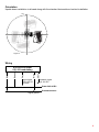
>15 cm
(5.91 in.)
80 mm
(3.15 in.)
73,6
mm
(2.9 in.)
49 mm
(1.93 in.) MAX 50 °C
122 °F
MIN 0 °C
32 °F
MAX 90 RH%
MIN 10 RH%
MAX 95 °C
203 °F
MIN 0 °C
32 °F
• Pollution degree 2
• Degré de pollution 2
• Verschmutzungsgrad 2
• Grado di insudiciamento 2
• Grado de suciedad 2
• Vervuilingsgraad 2
• Grad av nedsmutsningsgrad 2
• Stupeň znečištění 2
• Stopień zanieczyszczenia 2
• Степень загрязнения 2
• Posição alcançada 2
• 污染程度 2
• Green • Vert • Grün • Verde • Verde • Groen
• Grön • Zelený • Zielony • зеленый • Verde • 绿色
• Red • Rouges • Rot • Rosso • Rojo • Rood • Rött
• Červený • Czerwony • Красный • Vermelho • 红色的
• OFF
• OFF
• AUS
• Spento
• Apagado
• UIT
• AV
• OFF
• Wyłączony
• Выкл.
• Desligado
• 关闭
• Moving to Position
• Aller en position
• Motor fährt zur Hubposition
• In movimento verso la posizione
• Posicionando
• Positioneren
• Går till Position
• Pohyb na pozici
• Ruch do pozycji
• Отслеживание
• Em movimento para a posição
• 正在运转
• Position reached
• Position atteinte
• Hubposition erreicht
• Posizione raggiunta
• Posición alcanzada
• Positie bereikt
• Position nådd
• Pozice dosažena
• Pozycję osiągnięto
• Положение достигнуто
• Posição alcançada
• 运转到位
• Power on Calibration
• Calibration en cours
• Kalibrierungszyklus
• Calibrazione in corso
• Calibración al encendido
• Voeding aan en kalibreren
• Spänning på Kalibrering
• Probíhá kalibrace
• Kalibrowanie
• Происходит калибровка
• Calibração na inicialização
• 正在校验
• Failure signal loss
• Perte du signal d’erreur
• Eingangssignal nicht vorhanden
• Mancaza di segnale
• Fallo perdida de señal
• Foutmelding geen stuursignaal
• Styrsignalfel
• Porucha - ztráta řídicího signálu
• Brak sygnału
• Сбой - потеря сигнала
• Falha, perda de sinal
• 无信号源
LED
• Compliance • Conformité • Konformität • Conformità • Conforme con • Voorschriften en normen • Överensstämmelse
• Shoda s požadavky norem a směrnic • Dane dotyczące zgodności • Соответствие стандартам • Conformidade
Giacomini S.p.A. declares that these products are in compliance with the essential requirements and other relevant provisions of the EMC Directive and Low Voltage Directive.
Giacomini S.p.A. déclare que ces produits sont conformes aux exigences essentielles et autres dispositions pertinentes de la Directive CEM et de la Directive basse tension.
Giacomini S.p.A. erklärt, dass diese Produkte konform sind mit den wesentlichen Anforderungen und sonstigen anwendbaren Bestimmungen der EMV-Richtlinie und der
Niederspannungsrichtlinie.
Giacomini S.p.A. dichiara che questi prodotti sono conformi ai requisiti fondamentali ed altre relative disposizioni della Direttiva EMC e della Direttiva bassa tensione.
Giacomini S.p.A. declara que estos productos cumplen los requisitos esenciales y demás disposiciones aplicables de la directiva EMC y la directiva europea de baja tensión.
Giacomini S.p.A. verklaart dat deze producten voldoen aan de essentiële vereisten en andere relevante bepalingen van de EMC-richtlijn en de richtlijn voor laagspanning.
Giacomini S.p.A. uppger att dessa produkter överensstämmer med kraven och andra relevanta bestämmelser i EMC-direktiv och lågspänningsdirektiv.
Giacomini S.p.A. prohlašuje, že tyto výrobky jsou v souladu se základními požadavky a ostatními odpovídajícími ustanoveními směrnice EMC a směrnice o nízkonapěťových zařízeních.
Firma Giacomini S.p.A. zapewnia, że te produkty spełniają podstawowe wymagania i inne istotne warunki dyrektywy dotyczącej zgodności elektromagnetycznej oraz dyrektywy
dotyczącej niskich napięć.
Giacomini S.p.A. заявляет, что данные изделия соответствуют основным требованиям и другим положениям Директивы по электромагнитной совместимости EMC и
Директивы по безопасности низковольтного оборудования.
Giacomini S.p.A. declara que este produto está em conformidade com os requisitos essenciais e outras disposições relevantes da directiva EMC e Baixa Tensão Directiva.

K281X012
P/N 14-88410-630 Rev. A Issue Date 07 2022
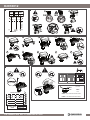
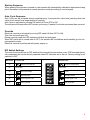
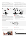
DIP SWITCH OPTIONS
1:
2:
3:
4:
5:
6:
ACTION
CURVE
SIGNAL TYPE
CONTROL SIGNAL
RANGE
OFF
0..10VDC
0..20mA
0..5VDC
5..10VDC
2..10VDC
4..20mA
DA RA
LIN Eq%
VDC mA
1 2 345 6
ON
OFF
ON
1 2 5
7
CLICK
CLICK
910
6
1
2
34
1
2
1
2
8
6
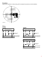
UMES: Upper Mechanical End Stroke
LMES: Lower Mechanical End Stroke
UMES
LMES
UMES
16.3 mm
LMES
10.0
4.3 mm
6
6 mm
6
3.2 mm
6
1
OK NO
2
NO
3
OK
4
BLK RED GRY
(-) (+)
24 VAC/DC
DC 0(2)...10 V
Factory Settings

K281X012
P/N 14-88410-630 Rev. A Issue Date 07 2022
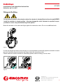
• READ THIS INSTRUCTION SHEET AND THE SAFETY WARNINGS CAREFULLY BEFORE INSTALLING AND SAVE IT FOR FUTURE USE
• All wiring should conform to local codes and must be carried out by authorized personnel only.
• Keep high and low voltage wiring separated.
• When using multi-stranded wire apply a cable ferrule to the cable end.
• Make sure that the line power supply is in accordance with the power supply specied on the device.
• Check all wiring connections before applying power to the system.
• Contact with components carrying hazardous voltage can cause electric shock and may result in severe injury or death.
• Short-circuited or improperly connected wires may result in permanent damage to the equipment.
• Not adhering to these operational instructions could cause injury or damage the equipment.
• This document is subject to change without notice.
INSTALLATION INSTRUCTIONS FOR THE TECHNICIAN / FITTER
en
• LISEZ ATTENTIVEMENT LES PRÉSENTES INSTRUCTIONS ET LES CONSIGNES DE SÉCURITÉ AVANT DE PROCÉDER À L’INSTALLATION
ET CONSERVEZ LES AUX FINS D’UTILISATION ULTÉRIEURE
• Le raccordement électrique doit être réalisé par le personnel autorisé conformément aux prescriptions locales.
• La tension d’alimentation et la basse tension doivent être amenées séparément.
• En cas d’utilisation de câbles exibles, il faut utiliser des cosses de câble.
• Assurez-vous que la tension d’alimentation coïncide avec les valeurs indiquées sur le vérin.
• Contrôlez toutes les liaisons par câble avant de mettre le vérin en circuit.
• Le contact avec des composants porteurs de tensions dangereuses peut causer une décharge électrique et peut entraîner des blessures graves ou la mort.
• Des ls en court-circuit ou mal branchés peuvent entraîner des dommages permanents pour l’équipement.
• Ne pas respecter le présent mode d’emploi peut provoquer des blessures ou endommager le matériel.
• Ce document peut être sujet à des modications sans préavis.
MANUEL D’INSTALLATION POUR LE SPECIALISTE / MONTEU
fr
• LESEN SIE DIESE ANLEITUNG UND DIE SICHERHEITSHINWEISE VOR DER INSTALLATION SORGFÄLTIG DURCH UND BEWAHREN SIE
SIE FÜR SPÄTERE REFERENZZWECKE AUF
• Der elektrische Anschluß ist nach den örtlichen Vorschriften durch autorisiertes Personal durchzuführen.
• Versorgungsspannung und Niederspannung sind getrennt zuzuführen.
• Bei Verwendung von exiblen Leitungen sind Kabelschuhe zu verwenden.
• Stellen Sie sicher das die Versorgungsspannung mit dem angegebenen Wert des Antriebes übereinstimmt.
• Überprüfen Sie alle Kabelverbindungen bevor Sie den Antrieb einschalten.
• Der Kontakt mit Komponenten, auf denen gefährliche Spannung anliegt, kann zu einem Stromschlag führen und schwere Körperschäden oder sogar den Tod zur Folge
haben.
• Kurzgeschlossene oder falsch angeschlossene Drähte können bleibende Schäden am Gerät verursachen.
• Die Missachtung dieser Bedienungsanleitung könnte zu Verletzungen oder zu Beschädigungen des Equipments führen.
• Änderungen ohne Ankündigung vorbehalten.
INSTALLATIONSANLEITUNG FÜR DIE FACHKRAFT / MONTEUR
de
• LEGGERE ATTENTAMENTE QUESTE ISTRUZIONI E LE AVVERTENZE PRIMA DELL’INSTALLAZIONE E CONSERVARLE PER USO FUTURO
• L’allacciamento elettrico deve essere eseguito da personale autorizzato e conformemente alle normative locali.
• La tensione di alimentazione e la bassa tensione devono essere alimentate separatamente.
• In caso di impiego di conduttori essibili usare degli ancoraggi per cavi.
• Assicurarsi che il valore della tensione di alimentazione corrisponda a quello prestabilito dell’attuatore.
• Prima di inserire l’azionamento controlare tutti gli allacciamenti dei cavi.
• Il contatto con componenti sottoposti a tensioni pericolose può causare scosse elettriche con conseguenti lesioni gravi o morte.
• I cavi in corto circuito o collegati impropriamente potrebbero causare danni permanenti all’apparecchiatura.
• Non attenersi alla presente istruzione operativa potrebbe causare danni alle persone o alle attrezzature.
• Questo documento è soggetto a modiche senza preavviso
ISTRUZIONI D’INSTALLAZIONE PER IL PERSONALE SPECIALIZZATO
it
• ANTES DE LA INSTALACIÓN, LEA ATENTAMENTE ESTAS INSTRUCCIONES Y LAS ADVERTENCIAS DE SEGURIDAD,Y CONSÉRVELAS
PARA SU USO FUTURO
• La conexión eléctrica deberá ser realizada según las disposiciones locales y por personal autorizado.
• La tensión de alimentación y la baja tensión deben tenderse por separado.
• Al usar cables exibles, deberán utilizarse terminales de cable.
• Asegurar que la tensión de alimentación coincida con el valor indicado para el accionamiento.
• Comprobar todas las conexiones de cables, antes de conectar el accionamiento.
• El contacto con elementos portadores de alto voltaje puede provocar una descarga eléctrica y producir lesiones graves o incluso la muerte.
• Los cables cortocircuitados o mal conectados pueden provocar daños permanentes en el equipo.
• El incumplimiento de estas instrucciones de funcionamiento puede causar lesiones personales o daños en el equipo.
• Este documento está sujeto a cambios sin previo aviso.
INSTRUCCIONES TÉCNICAS DE INSTALACIÓN
es
• LEES DIT INSTRUCTIEBLAD EN DE VEILIGHEIDSWAARSCHUWINGEN ZORGVULDIG VOORDAT DE INSTALLATIE WORDT UITGEVOERD,
EN BEWAAR DIT MATERIAAL ZODAT U HET IN DE TOEKOMST OOK NOG KUNT RAADPLEGEN
• De elektrische aansluiting moet volgens de plaatselijke voorschriften door geautoriseerd personeel uitgevoerd worden.
• Voedingsspanning en laagspanning moeten afzonderlijk toegevoerd worden.
• Bij het gebruik van exibele leidingen moeten kabelschoenen gebruikt worden.
• Zorg ervoor dat de voedingsspanning met de opgegeven waarde van de aandrijving overeenstemt.
• Controleer alle kabelverbindingen voor u de aandrijving inschakelt.
• Contact met onderdelen met een gevaarlijke spanning kan elektrische schokken veroorzaken en ernstig letsel of de dood tot gevolg hebben.
• Kortsluitingen of verkeerd aangesloten bedradingen kunnen permanente schade aan de apparatuur tot gevolg hebben.
• Het niet naleven van deze gebruiksinstructies kan leiden tot persoonlijk letsel of schade aan de apparatuur.
• Dit document kan zonder kennisgeving worden gewijzigd.
INSTALLATIEHANDLEIDING VOOR DE VAKMAN / MONTEUR
nl

K281X012
P/N 14-88410-630 Rev. A Issue Date 07 2022
• LÄS DET HÄR INSTRUKTIONSBLADET OCH SÄKERHETSANVISNINGARNA NOGGRANT INNAN DU INSTALLERAR MODULEN OCH
SPARA DEM FÖR FRAMTIDA BRUK
• Elanslutningen ska utföras av behörig personal i enlighet med de lokala föreskrifterna.
• Försörjningsspänning och lågspänning ska tillföras åtskilt.
• Vid användning av exibla ledningar ska kabelskor användas.
• Säkerställ att försörjningsspänningen stämmer överens med det angivna värdet för ställdonet.
• Kontrollera alla kabelförbindelser innan du tillkopplar ställdonet.
• Kontakt med komponenter med farlig spänning kan ge elektriska stötar som kan orsaka allvarliga eller livshotande personskador.
• Kortslutna eller felaktigt anslutna kablar kan resultera i varaktiga skador på utrustningen.
• Om innehållet i den här bruksanvisningen inte efterföljs kan det leda till skada på person eller utrustning.
• Det här dokumentet kan ändras utan föregående meddelande.
INSTALLATIONSGUIDE FÖR INSTALLATÖR / MONTÖR
se
• PŘED INSTALACÍ SI POZORNĚ PŘEČTĚTE TYTO POKYNY A BEZPEČNOSTNÍ VAROVÁNÍ A USCHOVEJTE JE PRO POZDĚJŠÍ POUŽITÍ
• Veškerá zapojení by měla odpovídat místním předpisům a musí být prováděna pouze oprávněnými pracovníky.
• Vysokonapěťová a nízkonapěťová vedení oddělte.
• Pri použití vícežilového kabelu instalujte do pruchodky gumový tesnicí kroužek.
• Zkontrolujte, zda síťový zdroj odpovídá požadovanému zdroji napájení, který je uveden na zařízení.
• Před připojením systému ke zdroji napájení proveďte kontrolu všech zapojení.
• Kontakt se součástmi, které jsou pod napětím, může způsobit zasažení elektrickým proudem a vážný úraz nebo smrt.
• Zkratované nebo nesprávně připojené vodiče mohou způsobit nevratné poškození zařízení.
• Nedodržení těchto provozních pokynů by mohlo způsobit zranění nebo poškození zařízení.
• Tento dokument podléhá změnám bez předchozího upozornění.
POKYNY K INSTALACI PRO TECHNIKY A MONTÉRY
cz
• PRZED INSTALACJĄ NALEŻY UWAŻNIE PRZECZYTAĆ TĘ INSTRUKCJĘ I OSTRZEŻENIA DOTYCZĄCE BEZPIECZEŃSTWA ORAZ ZACHOWAĆ
JE W CELU PÓŹNIEJSZEGO UŻYCIA
• Okablowanie musi być zgodne z lokalnymi przepisami i jego montaż musi być przeprowadzany wyłącznie przez uprawniony personel.
• Należy odseparować kable niskiego napięcia od okablowania wysokiego napięcia.
• W przypadku stosowania kabla wielożyłowego należy założyć tulejkę na jego koniec.
• Należy upewnić się, że źródło zasilania jest zgodne z parametrami zasilania określonymi na urządzeniu.
• Przed włączeniem zasilania systemu należy sprawdzić wszystkie połączenia kabli.
• Dotknięcie elementów będących pod niebezpiecznym napięciem może spowodować porażenie i poważne obrażenia lub nawet śmierć.
• Zwarcia lub nieprawidłowo podłączone kable mogą spowodować trwałe uszkodzenie urządzeń.
• Nieprzestrzeganie niniejszych instrukcji użytkowania może spowodować obrażenia lub uszkodzenie sprzętu.
• Informacje zawarte w tym dokumencie mogą ulec zmianie bez powiadomienia.
INSTRUKCJA INSTALACJI DLA TECHNIKA/MONTERA
pl
ИНСТРУКЦИЯ ПО УСТАНОВКЕ ДЛЯ ТЕХНИКА/МОНТАЖНИКА
ru
• ПЕРЕД УСТАНОВКОЙ ВНИМАТЕЛЬНО ПРОЧИТАЙТЕ НАСТОЯЩУЮ ИНСТРУКЦИЮ И УКАЗАНИЯ ПО ОБЕСПЕЧЕНИЮ БЕЗОПАСНОСТИ,
СОХРАНИТЕ ЭТУ ИНСТРУКЦИЮ ДЛЯ ПОСЛЕДУЮЩЕГО ИСПОЛЬЗОВАНИЯ
• Все электрические цепи и соединения должны соответствовать местным нормам и правилам и должны выполняться только уполномоченным персоналом.
• Прокладывайте цепи высокого и низкого напряжения отдельно.
• В случае применения много жильного провода заключите конец провода в наконечник.
• Удостоверьтесь в том, что напряжение питающей сети соответствует напряжению питания, которое указано на корпусе устройства.
• Проверьте все проводные соединения, прежде чем подавать питание на систему.
• Прикосновение к частям и элементам, находящимся под опасным напряжением, может привести к серьезному увечью или смерти в результате поражения
электротоком.
• Короткое замыкание или неправильное подключение электрических цепей может привести к неустранимому повреждению оборудования.
• Несоблюдение настоящих указаний может стать причиной несчастного случая или повреждения оборудования.
• Настоящий документ может быть изменен без уведомления.
• LEIA ESTE FOLHA DE INSTRUÇÕES E OS AVISOS DE SEGURANÇA ANTES DE INSTALAR E GUARDAR PARA USO FUTURO
• Toda a ação eletrica devera ser realizadas segundo a disposicão locais e apenas por pessoal autorizado
• Manter os os de alta tensão e baixa separados.
• Ao usar o exivel aplicar na extremidade do cabo terminais.
• Certique-se que o fornecimento de energia da linha está de acordo com a fonte de alimentação especicada no dispositivo.
• Verique todas as ligações antes de ligar para o sistema.
• Contato com os componentes portadores de alte tensão pode provocar choque elétrico e podem resultar ferimentos graves ou morte.
• Curto-circuito ou os mal conectados podem provocar danos permanentes no equipamento.
• Não aderir a estas instruções operacionais pode provocar ferimentos ou danos ao equipamento.
• Este documento está sujeito a alterações, sem aviso prévio.
INSTRUÇÕES DE INSTALAÇÃO PARA O TÉCNICO/INSTALADOR
pt
• 安装前请仔细阅读安装说明书和安全警示,并保留以备将来使用
• 所有接线必须符合当地电器规范,并由具有资质的人员进行接线
• 将高压和低压线分离
• 当使用多股线时,请在电缆末端安装金属套圈
• 确保所接的电源规格符合产品所规定的电源要求
• 系统通电前检查所有接线是否准确
• 触碰带有危险电压的部件可能引起触电,并可导致人员受伤或死亡
• 短路或者错误接线会导致设备永久性损坏
• 不遵守这些操作指南会导致人员受伤或者机器损坏
• 本文档如有变化,恕不另行通知
适用于技术人员与安装人员的安装说明书
cn

1
Installation and operation instruction
Actuator 24 V, 0÷10 V (with green indicators)
K281X032 Instruction
11/ 2 0 22
Giacomini S.p.A.
Via per Alzo 39, 28017 San Maurizio d’Opaglio (NO) Italia
+39 0322 923372 - giacomini.com
Fitting and Re-fitting
Do not connect power to the actuator unless the actuator is already fitted on the valve and
NEVER install the actuator in closed position - this may damage the valve. Actuator is sup-
plied in open position to ensure easy commissioning of the system.
Mount the actuator on the valve and finger
tighten the connection union.
Do not use additional tools.
In case the actuator will have to be removed, it is recommended to electrically open the actuator by
activating DIP switch #6 for easier removal.
Hereafter, disconnect power and finger loosen the connection union.
Again, no need for additional tools.
Please make sure that the actuator is electrically opened, before re-fitting it on the valve.
Figure 1
Figure 2

2
Orientation
Upside-down installation is allowed along with the standard horizontal and vertical installation.
360º
Figure 3
Wiring
Blue
Yellow
Power 24V AC/DC
Ground/common
Green
Grey
Feedback signal
0(2)-10V DC
Signal ground
Input signal
0(2)-10V DC
<0.5mA
Brown
K281X032 Actuator
0(2)-10V modulating

3
Start-up Sequence
When power to the actuator is turned on, the actuator will automatically calibrate to determine closing
point. Hereafter it will proceed to normal operation mode (according to control signal).
Auto Cycle Sequence
Auto Cycle can be activated during commissioning. It prevents the valve from jamming when the
valve is not moved for a longer period of inactivity.
Auto Cycle is activated by moving DIP switch #1 from OFF to ON.
The actuator will then perform 50% stroke cycle every 3 weeks if not stroke movement has occurred.
Override
Electrical override is activated by moving DIP switch #6 from OFF to ON.
Then the valve will open fully.
During override mode the LED indicator will blink red and green.
When DIP switch #6 is moved back to OFF, the actuator will re-calibrate and thereafter go into nor-
mal operation mode.
Electrical override is performed with power supply on.
DIP Switch Settings
The valve functions are set on DIP switches found under the connection cover. PCB mounted electri-
cal components will not be directly exposed when DIP switches are to be set. Factory setting for all
switches is OFF.
DIP switch Function ON Function OFF
#6 Electrical override ON Electrical override OFF
#5 No function No function
#4 Equal percentage Linear
#3 Normally Open Normally Closed
#2 Control signal 2-10V Control signal 0-10V
#1 Auto cycle ON Auto cycle OFF
6
5
4
3
2
1
%%
%%
%%
%%
%%
%%
%%
%%
%%
%%

4
Package Disposal. Carton boxes: paper recycling. Plastic bags and bubble wrap: plastic
recycling.
Product Disposal. Do not dispose of product as municipal waste at the end of its life cycle.
Dispose of product at a special recycling platform managed by local authorities or at retailers
providing this type of service.
Safety Warning. Installation, commissioning and periodical maintenance of the product
must be carried out by qualied operators in compliance with national regulations and/or local
standards. A qualied installer must take all required measures, including use of Individual
Protection Devices, for his and others’ safety. An improper installation may damage people,
animals or objects towards which Giacomini S.p.A. may not be held liable.
Additional information. For more information, go to giacomini.com or contact our technical
assistance service. This document provides only general indications. Giacomini S.p.A. may
change at any time, without notice and for technical or commercial reasons, the items included
herewith. The information included in this technical sheet do not exempt the user from strictly
complying with the rules and good practice standards in force.
Imported by GIACOMINI U.K.
Unit 2, Goodrich Close, Westerleigh Business Park,
Yate, South Gloucestershire, BS37 5YT.
suppor[email protected] 01454311012
Designed and produced by FlowCon International ApS
Trakcenter Allé 17 / 4200 Slagelse / Denmark
Giacomini S.p.A.
Via per Alzo 39, 28017 San Maurizio d’Opaglio (NO) Italia
+39 0322 923372 - giacomini.com
Re-Calibration
Re-calibration can be achieved in one of 2 ways:
1. Forced individual actuator re-calibration can also be performed by flipping DIP switch #6
from OFF to ON and back to OFF on the relevant actuator.
2. Forced concurrent re-calibration for all modulating actuators is electrically possible. Within 60
sec. provide the following electrical control signal sequence to the grey wire: 10V-2V-10V-2V-
10V-2V to achieve re-calibration.
After re-calibration the actuator will go into normal operation mode.
LED Status
The LED indicator is visible through the dark colored transparent connection cover.
The LED indication will give the following statuses.
K281X032
Normal operation mode Full on green
Calibration mode
(closing point adjustment) Blinking green
Electrical override mode Blinking red/green
Perpetual failure mode Full on red

1
Installation and operation instruction
Actuator 24 V, 0÷10 V
K281X042 Instruction
11/ 2 0 22
Giacomini S.p.A.
Via per Alzo 39, 28017 San Maurizio d’Opaglio (NO) Italia
+39 0322 923372 - giacomini.com
Fitting and Re-fitting
Do not connect power to the actuator unless the actuator is already fitted on the valve and NEVER
install the actuator in closed position - this may damage the valve. Actuator is supplied in open
position to ensure easy commissioning of the system.
Mount the actuator on the valve and finger tighten the connection union. Do not use additional tools.
Figure 1
In case the actuator will have to be removed, it is recommended to electrically open the actuator for easier
removal. Hereafter disconnect power and finger loosen the connection union.
Please make sure that the actuator is electrically opened, before re-fitting it on the valve.
Figure 2

2
Orientation
Upside-down installation is allowed along with the standard horizontal and vertical installation.
360º
Figure 3
Blue
Yellow
Power 24V AC/DC
Ground/common
Green
Grey
Feedback signal
0(2)-10V DC
Signal ground
Input signal
0(2)-10V DC
<0.5mA
Brown
K281X042 Actuator
0(2)-10V modulating
analog
Blue
Power 24V AC/DC
Ground/common
Grey
Open
Stop
K281X042 Actuator
3-Point Floating, Normally Closed
Brown
Close
Yellow
Signal ground
Green
Feedback signal
0(2)-10V DC
Blue
Power 24V AC/DC
Ground/common
Grey
Brown
Open
K281X042 Actuator
2-Position, Normally Closed
Close
Yellow
Green
Feedback signal
0-10V DC
Signal ground
digital
Wiring

3
Start-up Sequence
When power to the actuator is turned on, the actuator will automatically calibrate to determine closing
point. Hereafter it will proceed to normal operation mode (according to control signal).
Auto Cycle Sequence
Auto Cycle can be activated during commissioning. It prevents the valve from jamming
when the valve is not moved for a longer period of inactivity. Auto Cycle is activated by mov-
ing DIP switch #1 from OFF to ON. The actuator will then perform 50% stroke cycle every
3 weeks if no stroke movement has occured.
Re-Calibration
By flipping DIP switch #6 from one setting to the other (starting position indifferent) re-calibration is acti-
vated. After completed re-calibration the actuator will automatically go into normal ope-ration. During re-
calibration mode the LED will blink green.
Override
Manual override is performed after power
supply is turned off. Lift the silicone cap on the top of the actuator
to get access to manual override. Manual override is performed by a 4 mm (~5/32”) hex key. Clockwise
turning will open the valve and counter-clockwise turning will close the valve.
DIP Switch Settings
The valve functions are set on DIP switches found under the connection cover. PCB mounted electrical
components will not be directly exposed when DIP switches are to be set. Factory setting for all switches
is OFF.
DIP switch Function ON Function OFF
#6 Re-calibration Re-calibration
#5 No function No function
#4 Equal percentage Linear
#3 Normally Open Normally Closed
#2 Control signal 2-10V Control signal 0-10V
#1 Auto cycle ON Auto cycle OFF
6
5
4
3
2
1
%%
%%
%%
%%
%%
%%
%%
%%
%%
%%

4
Package Disposal. Carton boxes: paper recycling. Plastic bags and bubble wrap: plastic
recycling.
Product Disposal. Do not dispose of product as municipal waste at the end of its life cycle.
Dispose of product at a special recycling platform managed by local authorities or at retailers
providing this type of service.
Safety Warning. Installation, commissioning and periodical maintenance of the product
must be carried out by qualied operators in compliance with national regulations and/or local
standards. A qualied installer must take all required measures, including use of Individual
Protection Devices, for his and others’ safety. An improper installation may damage people,
animals or objects towards which Giacomini S.p.A. may not be held liable.
Additional information. For more information, go to giacomini.com or contact our technical
assistance service. This document provides only general indications. Giacomini S.p.A. may
change at any time, without notice and for technical or commercial reasons, the items included
herewith. The information included in this technical sheet do not exempt the user from strictly
complying with the rules and good practice standards in force.
Imported by GIACOMINI U.K.
Unit 2, Goodrich Close, Westerleigh Business Park,
Yate, South Gloucestershire, BS37 5YT.
suppor[email protected] 01454311012
Designed and produced by FlowCon International ApS
Trakcenter Allé 17 / 4200 Slagelse / Denmark
Giacomini S.p.A.
Via per Alzo 39, 28017 San Maurizio d’Opaglio (NO) Italia
+39 0322 923372 - giacomini.com
LED Status
The LED indicator is visible through the dark colored transparent connection cover. The LED indication will
give the following statuses.
K281X042
Normal operation mode Full on green
Calibration mode (closing point adjustment) Blinking green
Perpetual failure mode Full on red
Re-Calibration
Re-calibration can be achieved in one of 2 ways:
1. Forced individual actuator re-calibration can also be performed by flipping DIP switch #6 from
OFF to ON and back to OFF on the relevant actuator.
2. Forced concurrent re-calibration for all actuators is electrically possible. Within 60 sec. provide
the following electrical control signal sequence to the grey wire: 10V-2V-10V-2V-10V-2V to
achieve re-calibration.
After re-calibration the actuator will go into normal operation mode.

K281X062
Motorised Electric Actuator with Auto Stroke Detection
P/N 14-88410-1025 _Rev. A_Issue Date 07 2022
Installation Instructions
GIACOMINI S.p.A.
Via per Alzo 39
28017 San Maurizio d’Opaglio (NO) Italy
www.giacomini.com
UK Importer
GIACOMINI U.K.
Unit 2, Goodrich Close, Westerleigh
Business Park
Yate, South Gloucestershire, BS37 5YT.
01454311012
>15 cm
(5.91 in.)
80 mm
(3.15 in.)
73,6
mm
(2.9 in.)
49 mm
(1.93 in.)
• Green • Vert • Grün • Verde • Verde
• Groen • Grön • Zelený • Zielony
• зеленый • Verde • 绿色
• Red • Rouges • Rot • Rosso • Rojo
• Rood • Rött • Červený • Czerwony
• Красный • Vermelho • 红色的
• Moving to Position
• Aller en position
• Motor fährt zur Hubposition
• In movimento verso la posizione
• Posicionando
• Positioneren
• Går till Position
• Pohyb na pozici
• Ruch do pozycji
• Отслеживание
• Em movimento para a posição
• 正在运转
• Position reached
• Position atteinte
• Hubposition erreicht
• Posizione raggiunta
• Posición alcanzada
• Positie bereikt
• Position nådd
• Pozice dosažena
• Pozycję osiągnięto
• Положение достигнуто
• Posição alcançada
• 运转到位
• Power on Calibration
• Calibration en cours
• Kalibrierungszyklus
• Calibrazione in corso
• Calibración al encendido
• Voeding aan en kalibreren
• Spänning på Kalibrering
• Probíhá kalibrace
• Kalibrowanie
• Происходит калибровка
• Calibração na inicialização
• 正在校验
• Temporary fault, possible valve sticking
• Erreur temporaire, calage possible de la vanne
• Temporärer Fehler, Ventil möglicherweise festsitzend
• Guasto temporaneo, possibile adesione della valvola
• Fallo temporal, posible bloqueo de la válvula
• Tijdelijke storing, ventiel mogelijk blijven hangen
• Tillfälligt fel, möjlig blockering av ventilen
• Dočasná chyba, pravděpodobně zaseknutí ventilu
• Usterka tymczasowa, możliwe zakleszczenie zaworu
• Временная неисправность, возможно заклинивание клапана
• Falha temporária, possível colagem das válvulas
• 暂时故障,可能是阀门粘连
• Failure signal loss
• Perte du signal d’erreur
• Eingangssignal nicht vorhanden
• Mancaza di segnale
• Fallo perdida de señal
• Foutmelding geen stuursignaal
• Styrsignalfel
• Porucha - ztráta řídicího signálu
• Brak sygnału
• Сбой - потеря сигнала
• Falha, perda de sinal
• 无信号源
LED
MAX
50°C (122°F)
MIN
0°C (32°F)
MAX
95°C (203°F)
MIN
0°C (32°F)
MAX
90 RH%
MIN
10 RH%
IP54 • Pollution degree 2 • Grad av nedsmutsningsgrad 2
• Degré de pollution 2 • Stupeň znečištění 2
• Verschmutzungsgrad 2 • Stopień zanieczyszczenia 2
• Grado di inquinamento 2 • Степень загрязнения 2
• Grado de suciedad 2 • Posição alcançada 2
• Vervuilingsgraad 2 • 污染程度 2
• Do not install in front of fans • Installera inte framför fläktarna
• Ne pas installer devant les fans • Neinstalujte před ventilátory
• Nicht vor Fans installieren • Nie instaluj przed wentylatorami
• Non installare davanti ai fan • не устанавливайте перед вентиляторами
• No instalar delante de los
ventiladores
• Não instalar o atuador na frente
dos ventiladores
• Installeer niet voor fans • 请勿安装在风扇前
• OFF
• OFF
• AUS
• Spento
• Apagado
• UIT
• AV
• OFF
• Wyłączony
• Выкл.
• Desligado
• 关闭
• Compliance • Conformité • Konformität • Conformità • Conforme con • Voorschriften en normen • Överensstämmelse
• Shoda s požadavky norem a směrnic • Dane dotyczące zgodności • Соответствие стандартам • Conformidade
Giacomini S.p.A. declares that these products are in compliance with the essential requirements and other relevant provisions of the EMC Directive and Low Voltage Directive.
Giacomini S.p.A. déclare que ces produits sont conformes aux exigences essentielles et autres dispositions pertinentes de la Directive CEM et de la Directive basse tension.
Giacomini S.p.A. erklärt, dass diese Produkte konform sind mit den wesentlichen Anforderungen und sonstigen anwendbaren Bestimmungen der EMV-Richtlinie und der
Niederspannungsrichtlinie.
Giacomini S.p.A. dichiara che questi prodotti sono conformi ai requisiti fondamentali ed altre relative disposizioni della Direttiva EMC e della Direttiva bassa tensione.
Giacomini S.p.A. declara que estos productos cumplen los requisitos esenciales y demás disposiciones aplicables de la directiva EMC y la directiva europea de baja tensión.
Giacomini S.p.A. verklaart dat deze producten voldoen aan de essentiële vereisten en andere relevante bepalingen van de EMC-richtlijn en de richtlijn voor laagspanning.
Giacomini S.p.A. uppger att dessa produkter överensstämmer med kraven och andra relevanta bestämmelser i EMC-direktiv och lågspänningsdirektiv.
Giacomini S.p.A. prohlašuje, že tyto výrobky jsou v souladu se základními požadavky a ostatními odpovídajícími ustanoveními směrnice EMC a směrnice o nízkonapěťových zařízeních.
Firma Giacomini S.p.A. zapewnia, że te produkty spełniają podstawowe wymagania i inne istotne warunki dyrektywy dotyczącej zgodności elektromagnetycznej oraz dyrektywy
dotyczącej niskich napięć.
Giacomini S.p.A. заявляет, что данные изделия соответствуют основным требованиям и другим положениям Директивы по электромагнитной совместимости EMC и
Директивы по безопасности низковольтного оборудования.
Giacomini S.p.A. declara que este produto está em conformidade com os requisitos essenciais e outras disposições relevantes da directiva EMC e Baixa Tensão Directiva.

K281X062
P/N 14-88410-1025_Rev. A_Issue Date 07 2022
1 2 3 5
7 8
CLICK
CLICK
910
6
2
1
1
2
2
11
2
4
BLK RED GRY
(-) (+)
24 VAC/DC
0...10 V
ORN
4
U
[***]
1
OK NO
2
NO
3
OK
4
1 2 3 4 5 6 7 8
ON
OFF
DIP SWITCH OPTIONS
5: CURVE
6: SIGNAL TYPE
7: NOT USED
0..10VDC
0..20mA
0..5VDC
5..10VDC
2..10VDC
4..20mA
DA RA
LIN Eq%
VDC mA
OFF
65
4
3
2
1
ON
11:
2:
3:
CONTROL SIGNAL
RANGE
NOT USED NOT USED
7
8: NOT USED
4:
ACTION
NOT USED NOT USED
8
Y(+)
[***]
UMES: Upper Mechanical End Stroke
LMES: Lower Mechanical End Stroke
UMES
LMES UMES 16.3 mm
LMES 10.0 mm K281X062
Factory Settings

K281X062
P/N 14-88410-1025_Rev. A_Issue Date 07 2022
• READ THIS INSTRUCTION SHEET AND THE SAFETY WARNINGS CAREFULLY BEFORE INSTALLING AND SAVE IT FOR FUTURE USE
• All wiring should conform to local codes and must be carried out by authorized personnel only.
• Keep high and low voltage wiring separated.
• When using multi-stranded wire apply a cable ferrule to the cable end.
• Make sure that the line power supply is in accordance with the power supply specied on the device.
• Check all wiring connections before applying power to the system.
• Contact with components carrying hazardous voltage can cause electric shock and may result in severe injury or death.
• Short-circuited or improperly connected wires may result in permanent damage to the equipment.
• Not adhering to these operational instructions could cause injury or damage the equipment.
• This document is subject to change without notice.
INSTALLATION INSTRUCTIONS FOR THE TECHNICIAN / FITTER
en
• LISEZ ATTENTIVEMENT LES PRÉSENTES INSTRUCTIONS ET LES CONSIGNES DE SÉCURITÉ AVANT DE PROCÉDER À
L’INSTALLATION ET CONSERVEZ LES AUX FINS D’UTILISATION ULTÉRIEURE
• Le raccordement électrique doit être réalisé par le personnel autorisé conformément aux prescriptions locales.
• La tension d’alimentation et la basse tension doivent être amenées séparément.
• En cas d’utilisation de câbles exibles, il faut utiliser des cosses de câble.
• Assurez-vous que la tension d’alimentation coïncide avec les valeurs indiquées sur le vérin.
• Contrôlez toutes les liaisons par câble avant de mettre le vérin en circuit.
• Le contact avec des composants porteurs de tensions dangereuses peut causer une décharge électrique et peut entraîner des blessures
graves ou la mort.
• Des ls en court-circuit ou mal branchés peuvent entraîner des dommages permanents pour l’équipement.
• Ne pas respecter le présent mode d’emploi peut provoquer des blessures ou endommager le matériel.
• Ce document peut être sujet à des modications sans préavis.
MANUEL D’INSTALLATION POUR LE SPECIALISTE / MONTEUR
fr
• LESEN SIE DIESE ANLEITUNG UND DIE SICHERHEITSHINWEISE VOR DER INSTALLATION SORGFÄLTIG DURCH UND BEWAHREN SIE
SIE FÜR SPÄTERE REFERENZZWECKE AUF
• Der elektrische Anschluß ist nach den örtlichen Vorschriften durch autorisiertes Personal durchzuführen.
• Versorgungsspannung und Niederspannung sind getrennt zuzuführen.
• Bei Verwendung von exiblen Leitungen sind Kabelschuhe zu verwenden.
• Stellen Sie sicher das die Versorgungsspannung mit dem angegebenen Wert des Antriebes übereinstimmt.
• Überprüfen Sie alle Kabelverbindungen bevor Sie den Antrieb einschalten.
• Der Kontakt mit Komponenten, auf denen gefährliche Spannung anliegt, kann zu einem Stromschlag führen und
schwere Körperschäden oder sogar den Tod zur Folge haben.
• Kurzgeschlossene oder falsch angeschlossene Drähte können bleibende Schäden am Gerät verursachen.
• Die Missachtung dieser Bedienungsanleitung könnte zu Verletzungen oder zu Beschädigungen des Equipments führen.
• Änderungen ohne Ankündigung vorbehalten.
INSTALLATIONSANLEITUNG FÜR DIE FACHKRAFT / MONTEUR
de
• LEGGERE ATTENTAMENTE QUESTE ISTRUZIONI E LE AVVERTENZE PRIMA DELL’INSTALLAZIONE E CONSERVARLE PER USO FUTURO
• L’allacciamento elettrico deve essere eseguito da personale autorizzato e conformemente alle normative locali.
• La tensione di alimentazione e la bassa tensione devono essere alimentate separatamente.
• In caso di impiego di conduttori essibili usare degli ancoraggi per cavi.
• Assicurarsi che il valore della tensione di alimentazione corrisponda a quello prestabilito dell’attuatore.
• Prima di inserire l’azionamento controlare tutti gli allacciamenti dei cavi.
• Il contatto con componenti sottoposti a tensioni pericolose può causare scosse elettriche con conseguenti lesioni gravi o morte.
• I cavi in corto circuito o collegati impropriamente potrebbero causare danni permanenti all’apparecchiatura.
• Non attenersi alla presente istruzione operativa potrebbe causare danni alle persone o alle attrezzature.
• Questo documento è soggetto a modiche senza preavviso
ISTRUZIONI D’INSTALLAZIONE PER IL PERSONALE SPECIALIZZATO
it
• ANTES DE LA INSTALACIÓN, LEA ATENTAMENTE ESTAS INSTRUCCIONES Y LAS ADVERTENCIAS DE SEGURIDAD,Y CONSÉRVELAS
PARA SU USO FUTURO
• La conexión eléctrica deberá ser realizada según las disposiciones locales y por personal autorizado.
• La tensión de alimentación y la baja tensión deben tenderse por separado.
• Al usar cables exibles, deberán utilizarse terminales de cable.
• Asegurar que la tensión de alimentación coincida con el valor indicado para el accionamiento.
• Comprobar todas las conexiones de cables, antes de conectar el accionamiento.
• El contacto con elementos portadores de alto voltaje puede provocar una descarga eléctrica y producir lesiones graves o incluso la muerte.
• Los cables cortocircuitados o mal conectados pueden provocar daños permanentes en el equipo.
• El incumplimiento de estas instrucciones de funcionamiento puede causar lesiones personales o daños en el equipo.
• Este documento está sujeto a cambios sin previo aviso.
INSTRUCCIONES TÉCNICAS DE INSTALACIÓN
es
• LEES DIT INSTRUCTIEBLAD EN DE VEILIGHEIDSWAARSCHUWINGEN ZORGVULDIG VOORDAT DE INSTALLATIE WORDT
UITGEVOERD, EN BEWAAR DIT MATERIAAL ZODAT U HET IN DE TOEKOMST OOK NOG KUNT RAADPLEGEN
• De elektrische aansluiting moet volgens de plaatselijke voorschriften door geautoriseerd personeel uitgevoerd worden.
• Voedingsspanning en laagspanning moeten afzonderlijk toegevoerd worden.
• Bij het gebruik van exibele leidingen moeten kabelschoenen gebruikt worden.
• Zorg ervoor dat de voedingsspanning met de opgegeven waarde van de aandrijving overeenstemt.
• Controleer alle kabelverbindingen voor u de aandrijving inschakelt.
• Contact met onderdelen met een gevaarlijke spanning kan elektrische schokken veroorzaken en ernstig letsel of de dood tot gevolg hebben.
• Kortsluitingen of verkeerd aangesloten bedradingen kunnen permanente schade aan de apparatuur tot gevolg hebben.
• Het niet naleven van deze gebruiksinstructies kan leiden tot persoonlijk letsel of schade aan de apparatuur.
• Dit document kan zonder kennisgeving worden gewijzigd.
INSTALLATIEHANDLEIDING VOOR DE VAKMAN / MONTEUR
nl

K281X062
P/N 14-88410-1025_Rev. A_Issue Date 07 2022
• LÄS DET HÄR INSTRUKTIONSBLADET OCH SÄKERHETSANVISNINGARNA NOGGRANT INNAN DU INSTALLERAR MODULEN OCH
SPARA DEM FÖR FRAMTIDA BRUK
• Elanslutningen ska utföras av behörig personal i enlighet med de lokala föreskrifterna.
• Försörjningsspänning och lågspänning ska tillföras åtskilt.
• Vid användning av exibla ledningar ska kabelskor användas.
• Säkerställ att försörjningsspänningen stämmer överens med det angivna värdet för ställdonet.
• Kontrollera alla kabelförbindelser innan du tillkopplar ställdonet.
• Kontakt med komponenter med farlig spänning kan ge elektriska stötar som kan orsaka allvarliga eller livshotande personskador.
• Kortslutna eller felaktigt anslutna kablar kan resultera i varaktiga skador på utrustningen.
• Om innehållet i den här bruksanvisningen inte efterföljs kan det leda till skada på person eller utrustning.
• Det här dokumentet kan ändras utan föregående meddelande.
INSTALLATIONSGUIDE FÖR INSTALLATÖR / MONTÖR
se
• PŘED INSTALACÍ SI POZORNĚ PŘEČTĚTE TYTO POKYNY A BEZPEČNOSTNÍ VAROVÁNÍ A USCHOVEJTE JE PRO POZDĚJŠÍ POUŽITÍ
• Veškerá zapojení by měla odpovídat místním předpisům a musí být prováděna pouze oprávněnými pracovníky.
• Vysokonapěťová a nízkonapěťová vedení oddělte.
• Pri použití vícežilového kabelu instalujte do pruchodky gumový tesnicí kroužek.
• Zkontrolujte, zda síťový zdroj odpovídá požadovanému zdroji napájení, který je uveden na zařízení.
• Před připojením systému ke zdroji napájení proveďte kontrolu všech zapojení.
• Kontakt se součástmi, které jsou pod napětím, může způsobit zasažení elektrickým proudem a vážný úraz nebo smrt.
• Zkratované nebo nesprávně připojené vodiče mohou způsobit nevratné poškození zařízení.
• Nedodržení těchto provozních pokynů by mohlo způsobit zranění nebo poškození zařízení.
• Tento dokument podléhá změnám bez předchozího upozornění.
POKYNY K INSTALACI PRO TECHNIKY A MONTÉRY
cz
• PRZED INSTALACJĄ NALEŻY UWAŻNIE PRZECZYTAĆ TĘ INSTRUKCJĘ I OSTRZEŻENIA DOTYCZĄCE BEZPIECZEŃSTWA
ORAZ ZACHOWAĆ JE W CELU PÓŹNIEJSZEGO UŻYCIA
• Okablowanie musi być zgodne z lokalnymi przepisami i jego montaż musi być przeprowadzany wyłącznie przez uprawniony personel.
• Należy odseparować kable niskiego napięcia od okablowania wysokiego napięcia.
• W przypadku stosowania kabla wielożyłowego należy założyć tulejkę na jego koniec.
• Należy upewnić się, że źródło zasilania jest zgodne z parametrami zasilania określonymi na urządzeniu.
• Przed włączeniem zasilania systemu należy sprawdzić wszystkie połączenia kabli.
• Dotknięcie elementów będących pod niebezpiecznym napięciem może spowodować porażenie i poważne obrażenia lub nawet śmierć.
• Zwarcia lub nieprawidłowo podłączone kable mogą spowodować trwałe uszkodzenie urządzeń.
• Nieprzestrzeganie niniejszych instrukcji użytkowania może spowodować obrażenia lub uszkodzenie sprzętu.
• Informacje zawarte w tym dokumencie mogą ulec zmianie bez powiadomienia.
INSTRUKCJA INSTALACJI DLA TECHNIKA/MONTERA
pl
ИНСТРУКЦИЯ ПО УСТАНОВКЕ ДЛЯ ТЕХНИКА/МОНТАЖНИКА
ru
• ПЕРЕД УСТАНОВКОЙ ВНИМАТЕЛЬНО ПРОЧИТАЙТЕ НАСТОЯЩУЮ ИНСТРУКЦИЮ И УКАЗАНИЯ ПО ОБЕСПЕЧЕНИЮ
БЕЗОПАСНОСТИ, СОХРАНИТЕ ЭТУ ИНСТРУКЦИЮ ДЛЯ ПОСЛЕДУЮЩЕГО ИСПОЛЬЗОВАНИЯ
• Все электрические цепи и соединения должны соответствовать местным нормам и правилам и должны выполняться только уполномоченным
персоналом.
• Прокладывайте цепи высокого и низкого напряжения отдельно.
• В случае применения много жильного провода заключите конец провода в наконечник.
• Удостоверьтесь в том, что напряжение питающей сети соответствует напряжению питания, которое указано на корпусе устройства.
• Проверьте все проводные соединения, прежде чем подавать питание на систему.
• Прикосновение к частям и элементам, находящимся под опасным напряжением, может привести к серьезному увечью или смерти в результате
поражения электротоком.
• Короткое замыкание или неправильное подключение электрических цепей может привести к неустранимому повреждению оборудования.
• Несоблюдение настоящих указаний может стать причиной несчастного случая или повреждения оборудования.
• Настоящий документ может быть изменен без уведомления.
• LEIA ESTE FOLHA DE INSTRUÇÕES E OS AVISOS DE SEGURANÇA ANTES DE INSTALAR E GUARDAR PARA USO FUTURO
• Toda a ação eletrica devera ser realizadas segundo a disposicão locais e apenas por pessoal autorizado
• Manter os os de alta tensão e baixa separados.
• Ao usar o exivel aplicar na extremidade do cabo terminais.
• Certique-se que o fornecimento de energia da linha está de acordo com a fonte de alimentação especicada no dispositivo.
• Verique todas as ligações antes de ligar para o sistema.
• Contato com os componentes portadores de alte tensão pode provocar choque elétrico e podem resultar ferimentos graves ou morte.
• Curto-circuito ou os mal conectados podem provocar danos permanentes no equipamento.
• Não aderir a estas instruções operacionais pode provocar ferimentos ou danos ao equipamento.
• Este documento está sujeito a alterações, sem aviso prévio.
INSTRUÇÕES DE INSTALAÇÃO PARA O TÉCNICO/INSTALADOR
pt
• 安装前请仔细阅读安装说明书和安全警示,并保留以备将来使用
• 所有接线必须符合当地电器规范,并由具有资质的人员进行接线
• 将高压和低压线分离
• 当使用多股线时,请在电缆末端安装金属套圈
• 确保所接的电源规格符合产品所规定的电源要求
• 系统通电前检查所有接线是否准确
• 触碰带有危险电压的部件可能引起触电,并可导致人员受伤或死亡
• 短路或者错误接线会导致设备永久性损坏
• 不遵守这些操作指南会导致人员受伤或者机器损坏
• 本文档如有变化,恕不另行通知
适用于技术人员与安装人员的安装说明书
cn

1
K281X082 (K281)
Istruzioni / Instruction
11/2 0 2 2
Attuatore proporzionale 0...10 V, per valvole PICV R206A
0...10 V proportional actuator for R206A PICVs
Giacomini S.p.A.
Via per Alzo 39, 28017 San Maurizio d’Opaglio (NO) Italia
consulenza.prodotti@giacomini.com
+39 0322 923372 - giacomini.com
Versioni e codici Versions and product codes
CODICE
PRODUCT CODE
ALIMENTAZIONE
POWER SUPPLY
TIPOLOGIA
TYPE
ATTACCO VALVOLA
VALVE CONNECTION
UTILIZZO CON VALVOLE
FOR USE WITH VALVES
K281X082 24 Vac/dc Proporzionale 0...10 V
Proportional 0...10 V M30 x 1,5 mm R206A
Dati tecnici Technical data
• Tipo di attuatore: proporzionale 0...10 V
• Alimentazione: 24 Vac/dc ± 10%
• Segnale di feedback: 2...10 V (2 V pistone retratto in azione diretta, 2 V
pistone esteso in azione inversa)
• Corsa massima: vedere tabella "Impostazione corsa ssa"
• Forza di spinta: 300 N (UNI 9497:1989)
• Tempo di apertura alla velocità massima: 5 s/mm
• Tempo di ritorno in emergenza: 3 s/mm
• Tempo di ricarica condensatore (per ritorno di emergenza): ~45 s
• Assorbimento elettrico:
carica condensatore: 12 W
in movimento: 6 W
mantenimento posizione: 1,5 W
• Assorbimento elettrico: 30 VA
• Classe di protezione: IP54
• Campo di temperatura ambiente di funzionamento: -5÷55 °C
con U.R. non condensante
• Lunghezza cavo elettrico: 5 li da 1,5 m (CEI 20-22/II)
• Ghiera per ssaggio al corpo valvola: M30x1,5 mm
• Peso: 400 g
• Comando manuale: tramite chiave esagonale da 3 mm
• Dimensioni: 89 x 123 x 86 mm
Materiali
• Guscio esterno: materiale polimerico autoestinguente
• Ghiera lettata: ottone
• Type of actuator: proportional 0...10 V
• Power supply: 24 Vac/dc ± 10%
• Feedback signal: 2...10 V (2 V direct-action retracted piston, 2 V reverse-
action extended piston)
• Max. stroke: see "Fixed stroke setting” table
• Thrust force: 300 N (UNI 9497:1989)
• Opening time at max speed: 5 s/mm
• Emergency return time: 3 s/mm
• Condenser recharging time (for emergency return): ~45 s
• Electric absorption:
condenser charge: 12 W
in motion: 6 W
position preservation: 1.5 W
• Electric absorption: 30 VA
• Protection class: IP54
• Room temperature working range: -5÷55 °C
with non-condensing R.H.
• Electric wire length: 5 1,5-m threads (CEI 20-22/II)
• Ring nut for connection to body valve: M30x1,5 mm
• Weight: 400 g
• Manual control: with 3-mm hexagonal wrench
• Dimensions: 89 x 123 x 86 mm
Materials
• Enclosure: self-extinguishing polymeric material
• Threaded ring nut: brass
AVVERTENZE.
• La valvola può essere installata in qualsiasi posizione ma è importante che l’attuatore non si
trovi in posizione sottosopra o con il cavo dell’alimentazione in entrata dall’alto (per evitare
possibili problemi dovuti all’eventuale condensa).
• Non coprire con materiale isolante.
Installazione Installation
WARNINGS.
• The valve may be installed in any position but the actuator should not be positioned upside
down or with the power cable entering from the top (to prevent problems deriving from
condensation).
• Do not cover with insulating material.
min. 100 mm
75° 75°

2
Collegamenti elettrici Electric connctions
AVVERTENZE.
• Assicurarsi che la tensione di alimentazione sia tolta durante la realizzazione delle connessioni.
• Effettuare e controllare i collegamenti elettrici prima di dare alimentazione al sistema.
Cortocircuiti o cavi non collegati correttamente potrebbero causare danni permanenti ai
componenti elettrici dell’attuatore.
• Non toccare né tentare di collegare o scollegare i cavi quando l’alimentazione elettrica è attiva.
• Tutto il cablaggio deve essere conforme alle normative locali e deve essere eseguito solo da
personale autorizzato.
• Tenere separati i cavi di alta e bassa tensione.
• Vericarechel’alimentazionedilineasiaconformeall’alimentazionespecicatasuldispositivo.
• Il mancato rispetto di queste istruzioni operative potrebbe causare lesioni alle persone o
danneggiare l’apparecchiatura.
(+)
(+)
(-)
(-)
(+) (-)
24 Vac/dc
Feedback
Segnale
Signal
ROSSO - RED
BIANCO - WHITE
BLU - BLUE
VERDE - GREEN
GIALLO - YELLOW
ATTUATORE
ACTUATOR
WARNINGS.
• Make sure to shut down the power supply before connecting the device.
• Wire the device and check the electric connections before powering the system. Short circuits
or improper wiring may permanently damage the electrical components of the actuator.
• Do not touch, try to connect or disconnect the wires with power ON.
• Wiringmustcomplytothelocalstandardsandmustbecarriedoutonlybyqualiedoperators.
• Keep high and low voltage wires separated.
• Make sure the line voltage complies with the one shown on the device.
• Failure to comply with these instructions may cause injuries or damage the device.
Installazione attuatore K281X082 su valvole R206A
Per installare l'attuatore sulla valvola R206A procedere come segue:
1) Rimuovere il volantino manuale della valvola;
2) Avvitare manualmente l’attuatore sul corpo valvola tramite la ghiera
lettata M30 x 1,5 mm e collegarlo elettricamente rispettando
scrupolosamente lo schema presente sulle istruzioni dello stesso.
2
K281X082
M30 x 1,5 mm
1
K281X082
M30 x 1,5 mm
NOTA . Prima di installare l'attuatore sulla valvola R206A vericare che il pistone di spinta
dell'attuatore sia tutto alzato (impostazione di fabbrica).
In caso contrario è necessario vincere la forza della molla del vitone della valvola.
AVVERTENZA.Conlacongurazionedifabbricalacorsadell’attuatoreècompatibile con le
valvole R206AY103/113/104/105/125.Prima di installarel'attuatoresu altrevalvole vericare il
valoredicorsaimpostatosull'attuatoreequellodellavalvolasucuiandràmontato.Congurareil
valore corretto tramite i relativi DIP.
Installation of K281X082 actuator on R206A valves
To install the actuator on the R206A valve, follow the steps below:
1) Remove the handwheel from the valve;
2) Screw the actuator on the valve body with the M30 x 1,5 mm threaded
ring nut and carefully wire it following the diagram included with the
instructions.
NOTE. Before installing the actuator on the R206A valve, make sure the thrust piston of the
actuator is all the way up (factory setting).
If positioned differently, the valve bonnet spring must be forced to reach the correct position.
WARNINGS. Actuators with a factory-setting stroke can be used with
R206AY103/113/104/105/125 valves. Before installing the actuator on other types of valves, check
the its stroke value and the value of the valve on which it will be installed. Set the correct value
through the corresponding DIPs.
Impostazione DIP Switch DIP Switch setting
L’attuatore viene fornito di fabbrica con predisposizione per segnale di
comando 0...10 V, corsa ssa 4,5 mm, azione inversa e funzione di ritorno in
emergenza su DOWN.
Per modicare le impostazioni procedere come segue:
1) Rimuovere la vite ed aprire il coperchio trasparente come indicato in gura.
2) Modicare la posizione dei DIP secondo la tabella seguente.
3) Le nuove impost. saranno attive al prossimo ciclo di spegnimento/accensione.
The actuator features a factory-setting 0...10 V control signal, a 4,5-mm xed
stroke, reverse action and emergency return set on DOWN.
To change the settings follow the steps below:
1) Remove the screw and open the clear cover as shown.
2) Change the position of the DIPs based on the table below.
3) The new settings will be implemented at the next shut down/start up cycle.
126 37 48 59
ON
Impostazione di fabbrica

3
Apprendimento corsa (valido solo se DIP4 OFF)
Questa funzione consiste nell’apprendere il tempo massimo di corsa della
valvola a cui l’attuatore viene accoppiato, in modo da poterla posizionare
correttamente seguendo il segnale di comando. Con attuatore alimentato
è ripetibile ogni volta che il DIP6 va da OFF a ON e il DIP4 è OFF.
Impostazione Corsa Fissa (DIP4, 6, 8, 9)
Attraverso il DIP4 viene scelto (in base alla valvola accoppiata) se la corsa deve
essere ssa o appresa automaticamente. In caso di corsa ssa (DIP4 ON) la
funzione di apprendimento corsa (DIP6) perde signicato in quanto il DIP6 con
DIP8 e DIP9 saranno usati per scegliere il valore della corsa ssa (vedi tabella).
DIP 6 DIP 8 DIP 9 CORSA VALVOLA - VALVE STROKE [mm]
OFF OFF OFF 2,5
OFF OFF ON 3
OFF ON OFF 3,5
OFF ON ON 4
ON OFF OFF 4,5
ON OFF ON 5
ON ON OFF 5,5
ON ON ON 6,5
Azione Diretta e Inversa (DIP1)
Attraverso il DIP 1 è possibile impostare l’attuatore in azione diretta (DIP1
OFF) o inversa (DIP1 ON). In azione diretta e senza segnale di comando la
posizione del pistone è verso l’alto (pistone retratto) con uscita feedback a 2 V,
mentre in azione inversa e senza segnale di comando la posizione del
pistone è verso il basso con feedback 2 V.
Impostazione Campi Segnale di Comando (DIP 2, 3, 5)
Attraverso i DIP2, 3 e 5 è possibile impostare 5 diversi campi di ingresso.
Se il DIP5 è ON, il campo di ingresso è settato su 4÷20 mA e i DIP2 e 3
perdono signicato. Se il DIP5 è OFF, i campi gestiti sono: 0÷10/2÷10 con
DIP3 OFF, 0÷5/6÷10 con DIP3 ON.
Posizionamento iniziale
Viene eseguito ogni volta che l’attuatore viene alimentato e prima di aver
eseguito l’apprendimento della corsa.
Questa operazione permette all’attuatore di partire da una posizione certa
per poi seguire il segnale di comando.
Tale posizione dipende dalla selezione eettuata sul DIP1 (DIP4 OFF).
Funzione Stallo inatteso
Se viene riconosciuto un impuntamento nella corsa, questa funzione ha lo
scopo di sbloccarlo. L’attuatore verrà comandato in direzione opposta per
poi riprovare a raggiungere la posizione e verranno eseguiti 3 tentativi.
Nel caso non si fosse sbloccato dopo i primi 3 tentativi, dopo una pausa di 1
minuto vengono eseguiti ulteriori 3 tentativi.
Uscita feedback (2÷10V)
L’attuatore dispone di un’uscita dedicata per fornire il segnale di feedback
della posizione presunta dell’attuatore.
Questo segnale può variare da 2 a 10 V.
Durante la fase di “Apprendimento corsa” e “Posizionamento iniziale” il
segnale rimane sso a 2 V.
Durante la fase di ritorno in emergenza il segnale di feedback rimane sso a 1 V.
Comando manuale
Per azionare il comando manuale rimuovere l’alimentazione, rimuovere il
coperchio trasparente e inserire una chiave esagonale da 3 mm nel foro
frontale e ruotare la chiave no a quando non si è raggiunta la posizione
desiderata.
Stroke self-calibration (only for DIP4 OFF)
This function enables the device to read the max stroke time of the valve
to which the actuator is combined so as to position it correctly according
to the control signal. When the actuator is powered, this function can be
repeated every time DIP6 turns from OFF to ON and DIP4 is OFF.
Fixed stroke settings (DIP4, 6, 8, 9)
Through DIP4, the stroke can be xed or set automatically (based on the
valve used). There is no need to use the stroke self-calibration function
(DIP6) in case of xed stroke (DIP4 ON) as DIP6 with DIP8 and DIP9 will be
used to select the value of the xed stroke (see table).
Direct and Reverse Action (DIP1)
By using DIP 1 the actuator can be set on direct action (DIP1 OFF) or
reverse action (DIP1 ON). With direct action and no control signal, the
piston is positioned upwards (retracted piston) with a 2-V feedback outlet,
while with reverse action and no control signal, the piston is positioned
downwards with a 2 V feedback.
Setting up the Control Signal Fields (DIP 2, 3, 5)
DIP2, 3 and 5, 5 enable to set various inlet elds.
When DIP5 is ON, the inlet eld is set on 4÷20 mA and there is no need to
use DIP2 and 3. When DIP5 is OFF, the controlled elds are: 0÷10/2÷10 with
DIP3 OFF, 0÷5/6÷10 with DIP3 ON.
Initial positioning
This is performed every time the actuator is powered and before
implementing the stroke self-calibration function.
Thanks to this operation the actuator can start from a known position and
then follow the control signal.
This position depends on the selection of DIP1 (DIP4 OFF).
Sudden-stall function
This function unlocks the stroke in case of locking.
The actuator will be moved in the opposite direction and then perform
three attempts to reach the setting position.
If the unlocking fails after the rst 3 attempts, the actuator will perform 3
additional attempts after 1 minute.
Feedback outlet (2÷10V)
The actuator features a dedicated outlet to provide a feedback signal for
the actuator expected position.
The signal may vary from 2 to 10 V.
During “Self-calibration” and “Initial positioning” the signal will be xed on
2 V.
During the emergency return phase, the feedback signal will be xed on 1 V.
Manual control
For manual control, shut o the power, remove the clear cover and insert
a 3-mm hexagonal wrench into the front hole, then turn the wrench till the
actuator reaches the desired position.
NOTA . L’attuatore può essere accoppiato a valvole con stelo senza ritorno a molla utilizzando la
funzione di apprendimento della corsa (DIP4 OFF), oppure a valvole con stelo con ritorno a molla
impostando la corsa della valvola (DIP4 ON).
DIP ON OFF
1Azione inversa
Reverse action
Azione diretta
Direct action
22÷10 / 6÷10 V 0÷10 / 0÷5 V
3Campi SEQ
SEQ elds
Campi NORM
NORM elds
4Corsa ssa
Fixed stroke
Corsa auto
Automatic stroke
54÷20 mA Campi in tensione
Fields under tension
DIP ON OFF
6Apprendimento corsa/Corsa ssa
Stroke self-calibration/Fixed stroke
Running/Corsa ssa
Running/Fixed stroke
7Ritorno in emergenza UP
Emergency return UP
Ritorno in emergenza DOWN
Emergency return DOWN
8Corsa ssa
Fixed stroke
Corsa ssa
Fixed stroke
9Corsa ssa
Fixed stroke
Corsa ssa
Fixed stroke
NOTE. The actuator can be combined to stem valves with no spring-return by using the stroke
self-calibration function (DIP4 OFF), or to stem valves with spring-return by setting the valve
stroke (DIP4 ON).

4
Avvertenze per la sicurezza. L’installazione, la messa in servizio e la periodica manutenzione
del prodotto devono essere eseguite da personale professionalmente abilitato, in accordo con
i regolamenti nazionali e/o i requisiti locali. L’installatore qualicato deve adottare tutti gli
accorgimenti necessari, incluso l’utilizzo di Dispositivi di Protezione Individuale, per assicurare la
propria incolumità e quella di terzi. L’errata installazione può causare danni a persone, animali o
cose nei confronti dei quali Giacomini S.p.A. non può essere considerata responsabile.
Safety Warning. Installation, commissioning and periodical maintenance of the product
mustbecarriedoutbyqualiedoperatorsincompliancewithnationalregulationsand/orlocal
standards. A qualied installer must take all required measures, including use of Individual
Protection Devices, for his and others’ safety. An improper installation may damage people,
animals or objects towards which Giacomini S.p.A. may not be held liable.
Smaltimento imballo. Scatole in cartone: raccolta differenziata carta. Sacchetti in plastica e
pluriball: raccolta differenziata plastica.
Package Disposal. Carton boxes: paper recycling. Plastic bags and bubble wrap: plastic
recycling.
Smaltimentodelprodotto.Allanedelsuociclodivitailprodottonondeveesseresmaltito
comeriutourbano.Puòessereportatoaduncentrospecialediriciclaggiogestitodall’autorità
locale o ad un rivenditore che offre questo servizio.
Product Disposal. Do not dispose of product as municipal waste at the end of its life cycle.
Dispose of product at a special recycling platform managed by local authorities or at retailers
providing this type of service.
Altre informazioni. Per ulteriori informazioni consultare il sito giacomini.com o contattare il
servizio tecnico. Questa comunicazione ha valore indicativo. Giacomini S.p.A. si riserva il diritto di
apportareinqualunquemomento,senzapreavviso,modicheperragionitecnicheocommerciali
agli articoli contenuti nella presente comunicazione. Le informazioni contenute in questa
comunicazione tecnica non esentano l’utilizzatore dal seguire scrupolosamente le normative e le
norme di buona tecnica esistenti.
Additional information. For more information, go to giacomini.com or contact our technical
assistance service. This document provides only general indications. Giacomini S.p.A. may change
at any time, without notice and for technical or commercial reasons, the items included herewith.
The information included in this technical sheet do not exempt the user from strictly complying
with the rules and good practice standards in force.
Giacomini S.p.A.
Via per Alzo 39, 28017 San Maurizio d’Opaglio (NO) Italia
consulenza.prodotti@giacomini.com
+39 0322 923372 - giacomini.com
DESCRIZIONE
DESCRIPTION
DL1 (rosso)
DL1 (red)
DL2 (verde)
DL2 (green)
DL3 (giallo)
DL3 (yellow)
Fase di apprendimento
Self-calibration phase
Alternato 5 Hz
Alternated 5 Hz ON
Posizionamento iniziale
Initial positioning
Alternato 5 Hz
Alternated 5 Hz ON
Posizionamento UP
UP Positioning OFF Lampeggiante 1 Hz
Flashing 1 Hz ON
Fine corsa UP
UP stroke end OFF ON ON
Posizionamento DOWN
DOWN Positioning
Lampeggiante 1 Hz
Flashing 1 Hz OFF ON
Fine corsa DOWN
DOWN stroke end ON OFF ON
Attuatore fermo
Actuator stationary OFF OFF ON
Stallo inatteso
Sudden stall
Contemporaneo 5 Hz
Simultaneous 5 Hz ON
Tensione di alimentazione bassa
Low supply voltage OFF OFF Lampeggiante 1 Hz
Flashing 1 Hz
Tensione di alimentazione alta
High supply voltage OFF OFF Lampeggiante 5 Hz
Flashing 1 Hz
Corsa sotto il minimo
Stroke below min
Lampeggiante 1 Hz
Flashing 1 Hz ON ON
Corsa sopra il massimo
Stroke above max ON Lampeggiante 1 Hz
Flashing 1 Hz ON
Extra corsa
Extra stroke
Lampeggiante 5 Hz
Flashing 5 Hz OFF ON
Attuatore spento o sotto reset
(tensione di alimentazione bassa)
o ne ricarica supercap
Actuator OFF or resetting
(low supply voltage)
or end of supercap recharge
OFF OFF OFF
Ritorno in emergenza
Emergency return
Contemporaneo 1 Hz
Simultaneous 1 Hz OFF
Fase di ricarica dei supercap
Supercap recharging phase ON ON ON
Funzionamento LED LED operation
DL1 DL3
DL2
Imported by GIACOMINI U.K.
Unit 2, Goodrich Close, Westerleigh Business Park,
Yate, South Gloucestershire, BS37 5YT.
suppor[email protected] 01454311012
Designed and produced by iSMA CONTROLLI S.p.A.
Via Carlo Levi 52 / 16010 Sant’Olcese / Italia
-
 1
1
-
 2
2
-
 3
3
-
 4
4
-
 5
5
-
 6
6
-
 7
7
-
 8
8
-
 9
9
-
 10
10
-
 11
11
-
 12
12
-
 13
13
-
 14
14
-
 15
15
-
 16
16
-
 17
17
-
 18
18
-
 19
19
-
 20
20


in altre lingue
Documenti correlati
-
Giacomini K275 Istruzioni per l'uso
-
-
-
-
-
-
-
-
-
