Tecmate TM-34x OptiMate 4 Dual Program Manuale del proprietario
- Categoria
- Caricabatterie
- Tipo
- Manuale del proprietario

CZ
Automatic charger for 12V lead-acid batteries • Chargeur automatique pour
batteries 12V plomb-acide • Cargador automático para baterías 12V
plomo-ácido • Carregador automático para baterias de 12V chumbo-ácido •
Automatisches Ladegerät für 12V Blei-Säure Batterien • Automatische lader
voor 12V loodzuur accu’s • Caricabatterie automatico per batterie 12V
piombo-acido • Automatisk diagnostisk laddare för 12V blybatterier
Automatická nabíječka pro 12V olovo-kyselinové baterie
1 x 12V
STD / AGM-MF / GEL
3 - 50Ah (max. Ah rating based
on 48 hour charge).
+-
MODEL: TM340 / TM341 / TM342 / TM348
AC: 100 – 240V 50-60Hz
0.15A @ 240V / 0.28A @ 100V
DC: 12V 1A
INSTRUCTIONS FOR USE
IMPORTANT: Read completely
before charging
MODE D’EMPLOI
IMPORTANT: à lire avant
d’utiliser l’appareil
MODO DE EMPLEO
IMPORTANTE: a leer antes de
utilizar el aparato
ANWENDUNGSVORSCHRIFTEN
WICHTIG: Vollständig vor der
Benutzung lesen
GEBRUIKSAANWIJZING
BELANGRIJK: Lees volledig voor
gebruik
INSTRUÇÕES DE UTILIZAÇÃO
IMPORTANTE: Ler antes de
utilizar.
ISTRUZIONI PER L’USO
IMPORTANTE: da leggere prima
di utilizzare l’apparecchio
INSTRUKTIONER
VIKTIGT: läs följande fullständiga
instruktioner för användningen
innan du använder laddaren
1
4
SAVE
sulphated
battery
7
OPTIMIZE
25
Pulse
SAVE
8
TEST after
CHARGE
36
Controlled
CHARGE
9
OptiMate
‘365’
maintenance
TEST before
charge
Low Volt
Start (0.5V)
Pulse
Wake up
9
0.5V
13.6V
14.4V
3.TEST1.START 2.PULSE
0.5V
4 & 5.SAVE 6.CHARGE 7.OPTIMIZE 8.TEST 9.MAINTAIN
2V
INSTRUKCE PRO POUŽIT.
DŮLEŽIT: Přečtěte si pozorně
před použit.m
copyright © 2018 TecMate International – TM34x-IN1-180626
9 STEPS

LEDs
TEST LEDs
MAINTAIN
CHARGE
SAVE
12V
7
8
34
6
5
2
1
765
80 100%604020AGM
100% 806040STD
7665
0
0
CHARGE
48h max
MAINTAIN
365
SAVE
15m - 2h
TEST
30m - 12h
2: CAN-bus1: STD
TEST
10s
100-240Vac
2
55
Program LEDs
1
34
5
6
7
11
34
10 sec.
2. 5.3.1. 4.
Change program: Standard CAN-bus
2

3
IMPORTANT SAFETY
INSTRUCTIONS FOR CANADA & USA
THIS PORTION OF THE MANUAL CONTAINS IMPORTANT SAFETY INSTRUCTIONS FOR
THE OPTIMATE 4 BATTERY CHARGER. IT IS OF THE UTMOST IMPORTANCE THAT
EACH TIME, BEFORE USING THE CHARGER, YOU READ AND EXACTLY FOLLOW THESE
INSTRUCTIONS. SAVE THESE INSTRUCTIONS.
Automatic charger for 12V lead-acid batteries
DO NOT USE FOR NiCd, NiMH, Li-Ion OR NON-RECHARGEABLE BATTERIES.
1. CAUTION : CLASS II APPLIANCE. DO NOT CONNECT TO GROUND.
2. Do not expose charger to rain or snow.
3. Use of an attachment not recommended or sold by the battery charger manufacturer may result in a risk of fire, electric shock,
or injury to persons.
4. To reduce risk of damage to electric plug and cord, pull by plug rather than cord when disconnecting charger.
5. An extension cord should not be used unless absolutely necessary. Use of improper extension cord could result
in a risk of fire and electric shock. If extension cord must be used make sure that :
a) pins on plug of extension cord are the same number, size and shape as those of plug on charger.
b) the extension cord is properly wired and in good electrical condition, and
c) the conductor wire size is large enough for the AC ampere rating of the charger as specified in the table below.
AC INPUT RATING IN AMPERES
Equal to or greater than But less than LENGTH OF CORD,
FEET (m) AWG SIZE
OF CORD
2A 3A 25 (17.6)
50 (15.2)
100 (30.5)
18
18
14
6. Do not operate charger with damaged cord or plug – replace the cord or plug immediately.
7. Do not operate charger if it has received a sharp blow, been dropped,or otherwise damaged in any way;
take it to a qualified serviceman.
8. Do not disassemble charger; take it to a qualified serviceman when service or repair is required.
Incorrect reassembly may result in a risk of electric shock or fire.
9. To reduce risk of electric shock, unplug the charger from outlet before attempting any maintenance or cleaning.
Turning off controls will not reduce this risk.Clean only with slightly moist,not wet, cloth.Do not use solvents.
10. WARNING - RISK OF EXPLOSIVE GASES.
a) WORKING IN VICINITY OF A LEAD-ACID BATTERY IS DANGEROUS. BATTERIES GENERATE EXPLOSIVE GASES
DURING NORMAL BATTERY OPERATION. FOR THIS REASON, IT IS OF UTMOST IMPORTANCE THAT YOU FOLLOW THE
INSTRUCTIONS EACH TIME YOU USE THE CHARGER.
b) To reduce risk of battery explosion, follow these instructions and those published by the battery manufacturer
and manufacturer of any equipment you intend to use in vicinity of the battery. Review cautionary marking on
these products and on engine.
11. PERSONAL PRECAUTIONS.
a) Someone should be within range of your voice OR close enough to come to your aid when you work near a lead-acid battery.
b) Have plenty of fresh water and soap nearby in case battery acid contacts skin, clothing or eyes.
c) Wear complete eye protection and clothing protection. Avoid touching eyes while working near battery.
d) If battery acid contacts or enters eye, flood eye with cold running water for at least 10 minutes and get medical
attention immediately. If battery acid contacts skin or clothing, wash immediately with soap and water.
e) NEVER smoke or allow a spark or flame in vicinity of battery or engine.
f) Be extra cautious to reduce risk of dropping a metal tool onto battery. It might spark or short-circuit battery or other electrical
part that may cause explosion.
g) Remove personal metal items such as rings, bracelets, necklaces, and watches when working with a lead-acid
battery. A lead-acid battery can produce a short-circuit current high enough to weld a ring or the like to metal,
causing a severe burn.
i) NEVER charge a frozen battery.
SAFETY US & CAN

4
12. PREPARING TO CHARGE
a) If necessary to remove battery from vehicle to charge,always remove grounded terminal from battery first.
Make sure all accessories in the vehicle are off, so as not to cause an arc.
b) Be sure area around battery is well ventilated while battery is being charged. Gas can be forcefully
blown away by using a piece of cardboard or other non-metallic material as a fan.
c) Clean battery terminals. Be careful to keep corrosion from coming in contact with eyes.
d) Add distilled water in each cell until battery acid reaches level specified by battery manufacturer. This helps purge
excessive gas from cells. Do not overfill. For a battery without cell caps, such as valve regulated lead acid (VRLA) or absorbed glass
mat (AGM) batteries, carefully follow manufacturer’s recharging instructions.
e) Study all battery manufacturer’s specific precautions such as removing or not removing cell caps while charging
and recommended rates of charge.
f) Determine voltage of battery by referring to vehicle or battery user’s manual and BEFORE MAKING
THE BATTERY CONNECTIONS, MAKE SURE THAT THE VOLTAGE OF THE BATTERY YOU ARE GOING TO
CHARGE MATCHES THE OUTPUT VOLTAGE OF THE CHARGER.
13. CHARGER LOCATION.
a) Locate charger as far away from battery as DC cables permit.
b) Never place charger directly above batterv being charged; gases from battery will corrode and damage the charger.
c) Never allow battery acid to drip on charger when reading gravity or filling battery. Do not operate charger in a closed-in area or
restrict ventilation in any way.
d) Do not set a battery on top of charger. IMPORTANT : Place charger on a hard flat surface or mount onto a vertical surface. Do not
place on plastic, leather or textile surface.
14. DC CONNECTION PRECAUTIONS
a) Connect and disconnect DC output clips only after setting any charger switches to off position and removing AC
cord from electric outlet. Never allow clips to touch each other, however should this happen no damage will result to
the charger circuit & the automatic charging programme will just reset to «start».
b) Attach clips to battery and chassis as indicated in 15(e), 15(f), and 16(b) through 16(d).
NOTE : This battery charger has an automatic safety feature that will prevent it from operating if the
battery has been inversely connected. Set charger switches to off position and/or remove AC cord from electrical outlet,
disconnect the battery clips, then reconnect correctly according to the instructions below.
15. FOLLOW THESE STEPS WHEN BATTERY IS INSTALLED IN VEHICLE. A SPARK NEAR A BATTERY MAY CAUSE BATTERY
EXPLOSION. TO REDUCE RISK OF A SPARK NEAR BATTERY :
a) Position AC and DC cords so as to reduce risk of damage by hood, door or moving engine part.
b) Stay clear of fan -blades, belts,pulleys,and other parts that can cause injury to persons.
c) Check polarity of battery posts.POSITIVE (POS, P, +) battery post usually has larger diameter than NEGATIVE (NEG,
N,–) post.
d) Determine which post of battery is grounded (connected) to the chassis. If negative post is grounded to chassis
(as in most vehicles), see (e). If positive post is grounded to the chassis, see (f).
e) For negative-grounded vehicle, connect POSITIVE (RED) clip from battery charger to POSITIVE (POS, P, + )
ungrounded post of battery. Connect NEGATIVE (BLACK) clip to vehicle chassis or engine block away from battery.
Do not connect clip to carburetor, fuel lines, or sheet-metal body parts. Connect to a heavy gage metal part of the
frame or engine block.
f) For positive-grounded vehicle, connect NEGATIVE (BLACK) clip from battery charger to NEGATIVE (NEG. N , -)
ungrounded post of battery. Connect POSITIVE (RED) clip to vehicle chassis or engine block away from battery.
Do not connect clip to carburetor, fuel lines, or sheet-metal body parts. Connect to a heavy gage metal part of the
frame or engine block.
g) When disconnecting charger, turn switches to off, disconnect AC cord,remove clip from vehicle chassis,and then
remove clip from battery terminal.
h) See operating instructions for length of charge information.
16. FOLLOW THESE STEPS WHEN BATTERY IS OUTSIDE VEHICLE. A SPARK NEAR THE BATTERY MAY CAUSE BATTERY
EXPLOSION. TO REDUCE RISK OF A SPARK NEAR BATTERY :
a) Check polarity of battery posts. POSITIVE (POS, P, +) battery post usually has a larger diameter than NEGATIVE
(NEG,N, -) post.
b) This battery charger has an automatic safety feature that will prevent it from operating if the
battery has been inversely connected. The charger does not allow charge current unless a voltage of
at least 2V is sensed.
c) Connect POSITIVE (RED) charger clip to POSITIVE (POS, P, +) post of battery.
d) Connect NEGATIVE (BLACK) charger clip to NEGATIVE (NEG, N, -) battery post of the battery.
e) Do not face battery when making final connection.
f) When disconnecting charger, always do so in reverse sequence of connecting procedure & break first connection
while as far away from battery as practical.
g) A marine (boat) battery must be removed & charged on shore. To charge it on board requires equipment specially
designed for marine use.
SAFETY US & CAN

5
AUTOMATIC DIAGNOSTIC CHARGER FOR 12V LEAD-ACID BATTERIES.
DO NOT USE FOR NiCd, NiMH, Li-Ion OR NON-RECHARGEABLE BATTERIES.
IMPORTANT: READ THE FOLLOWING INSTRUCTIONS BEFORE USING THE CHARGER
This appliance can be used by children aged from 8 years and above and persons with reduced
physical,sensory or mental capabilities or lack of experience and knowledge if they have been given
supervision or instruction concerning use of the appliance in a safe way and understand the hazards
involved. Children shall not play with the appliance. Cleaning and user maintenance shall not be made
by children without supervision.
SAFETY WARNING AND NOTES: Batteries emit EXPLOSIVE GASES - prevent flame or sparks near batteries. Disconnect
AC power supply before making or breaking DC/battery connections. Battery acid is highly corrosive. Wear protective clothing and
eyewear and avoid contact. In case of accidental contact, wash immediately with soap and water. Check that the battery posts are
not loose; if so, have the battery professionally assessed. If the battery posts are corroded, clean with a copper wire brush; if greasy
or dirty clean with a rag damped in detergent. Use the charger only if the input and output leads and connectors
are in good, undamaged condition. If the input cable is damaged, it is essential to have it replaced
without delay by the manufacturer, his authorised service agent or a qualified workshop, to avoid
danger. Protect your charger from acid and acid fumes and from damp and humid conditions both during use and in storage.
Damage resulting from corrosion, oxidation or internal electrical short-circuiting is not covered by warranty. Distance the charger
from the battery during charging to avoid contamination by or exposure to acid or acidic vapours. If using it in the horizontal
orientation, place the charger on a hard, flat surface, but NOT on plastic, textile or leather. Use the fixing holes provided in the
enclosure base to attach the charger to any convenient, sound vertical surface.
EXPOSURE TO LIQUIDS: This charger is designed to withstand exposure to liquids accidentally spilled or splashed onto the
casing from above, or to light rainfall. Prolonged exposure to falling rain is inadvisable and longer service life will be obtained by
minimizing such exposure.Failure of the charger due to oxidation resulting from the eventual penetration of liquid into the electronic
components, connectors or plugs,is not covered by warranty.
CONNECTING THE CHARGER TO THE BATTERY
1. Disconnect AC power supply before making or breaking DC / battery connections.
2. If charging a battery in the vehicle with the battery clips, before making connections, first check that the battery clips can be
safely and securely positioned clear from surrounding wiring, metal tubing or the chassis. Make connections in the following
order: First connect to the battery terminal not connected to the chassis (normally positive), then
connect the other battery clip (normally negative) to the chassis well away from the battery and
fuel line. Always disconnect in reverse sequence.
3. When charging a battery out of the vehicle with the battery clips, place it in a well ventilated area. Connect the charger to the
battery: RED clamp to POSITIVE (POS, P or +) terminal and BLACK clamp to NEGATIVE (NEG, N or –) terminal. Make sure the
connections are firm and secure. Good contact is important.
4. If the battery is deeply discharged (and possibly sulphated), remove from the vehicle and inspect the battery before
connecting the charger for a recovery attempt. Visually check the battery for mechanical defects such as a bulging or
cracked casing, or signs of electrolyte leakage. If the battery has filler caps and the plates within the cells can be seen from the
outside, examine the battery carefully to try to determine if any cells seem different to the others (for example, with white
matter between the plates, plates touching). If mechanical defects are apparent do not attempt to charge the battery, have the
battery professionally assessed.
5. If the battery is new, before connecting the charger read the battery manufacturer’s safety and operational instructions
carefully. If applicable, carefully and exactly follow acid filling instructions.
PROCEEDING TO CHARGE:
DUAL PROGRAM: OptiMate 4 is equiped with two charging programs. Only one program can operate at a time. Selected models
of OptiMate 4 will be delivered with program 1 (STANDARD) or program 2 (CAN-bus) set as default.
Program 1 (STANDARD) is the normal charging program for direct connection to a battery in any condition. All program features are
active, including Standard, TURBO and PULSE desulfation mode.
Program 2 (CAN-bus) automatically activates a 12V outlet on vehicles fitted with CAN-bus, to charge, test and maintain the battery
when the vehicle is in storage. The standard and high voltage TURBO desulfation mode are de-activated. The low voltage PULSE
desulfation mode remains active, to recover a discharged battery that remains connected to vehicle wiring.
Program 2 can also be used to directly charge and maintain a battery in or out the vehicle, but cannot recover a sulfated battery.
To recover a sulfated battery select program 1 and follow instructions under VERY FLAT NEGLECTED BATTERIES.
Program indication when not connected to a 12V outlet or battery.
STANDARD – only the power LED#1 remains on.
SAFETY

6
CAN-bus – the POWER LED#1 remains on and DESULFATE LED#3 and CHARGE LED#4 briefly flash together at regular intervals.
POWER ON: LED #1 - Confirms AC power supply to the charger.
HIGH and LOW intensity indication: The"POWER ON" LED #1 will indicate brightly when current is delivered to the battery.
The "POWER ON" LED #1 will reduce intensity to a low level to indicate low power "ECO" mode. This will occur if there is no battery
connected, or when a battery is connected and the program finds itself in the voltage retention test mode or the 'rest' periods of
Maintenance Charge mode.
REVERSE POLARITY PROTECTION: LED #2 - Lights when the battery connections are incorrect. The charger is electronically protected
so no damage will result, and the output will remain disabled until the connections are corrected.
CAN-bus : LED #3, 4, 5, 6 and 7 flashing: A short circuit has been detected across the output terminals, or if LED #2 (REVERSE
POLARITY) is also indicating the battery connections are incorrect. The charger is electronically protected so no damage will result, and
the output will remain disabled until the connections are corrected.
STEP 1
Low Volt
START -
Bat ≥ 0.5V
V
STD: Battery voltage check - OptiMate 4 automatically activates if
connected battery voltage is at least 0.5 Volt.
Batteries measuring below 2 Volts at connection will proceed to
STEP 2 for 'Pulse wake up' that includes a battery short circuit test.
Batteries measuring 2 Volts or more will proceed directly to STEP 3.
CAN-Bus: LED #3 and 4 flashing: The program is sending a signal to detect and
activate a CAN-bus controlled 12V outlet. Non activation may be due to one of the
following: Program 1 is selected / Poor connection to the 12V outlet / Battery too low to
power CAN-bus / Outdated CAN-bus programming on the vehicle - consult with the
vehicle manufacturer.
STEP 2
Pulse
Wake
up
(< 2V)
LED #7 FLASHING Pulse wake up - LED #7 (red) flashing: OptiMate 4 is injecting a test signal to
see if the battery is recoverable.
Once the voltage holds above 2 Volts and no short circuit has been detected the
program will commence to STEP 3.
If flashing continues the following conditions may prevent the charge program
from progressing:
1) Vehicle circuitry remains connected to the battery.
NOTE: If the battery under charge is in a low voltage or suphated
state, for the most effective charge and test results disconnect the
battery from the vehicle circuitry and then charge.
2) Battery has multiple short circuited cells. The battery has permanent damage
and should be replaced.
STEP 3
TEST
before
charge
TEST LEDs
5 : GREEN
6 : YELLOW
7 : RED
TEST LEDs #5/6/7 indicate the battery condition prior to charging. Consult the table
below to match TEST LED indication to an estimated state of charge percentage
(SOC%). Charging commences after 10 seconds.
765
80 100%604020AGM
100% 806040STD
7665
0
0
Decisions made during the test: Severity of discharge is determined; a battery with
60% (AGM=40%) or more charge progresses directly to STEP 6 where-as a severely
discharged battery progresses to STEP 4 and 5.
Severely discharged batteries will undergo a longer test (up to 12 hours) during STEP 8.
STEP 4
ADVANCED
SAVE
LED #3 : RED Engages if the battery was diagnosed as sulphated,
unable to accept or hold charge.
Charge time: maximum 2 hours.
Output voltage increases to a maximum of 22V with current limited to 0.2A, but only if
no vehicle electronics have been detected, otherwise it moves directly to STEP 5.
IMPORTANT: Read section VERY FLAT NEGLECTED BATTERIES below.
CAN-Bus: Disabled in CAN-bus program.
STEP 5
PULSE
SAVE
LED #3 : RED Engages if the battery state of charge was 40% or less OR
battery has sufficiently recovered during ADVANCED SAVE.
CHARGE TIME : min 15 minutes, max. 2 hours.
Current is delivered in pulses to prepare the battery to accept normal charge.
This step is particularly effective for recovery of factory activated /
“hi-performance” pure lead or cyclic cell AGM batteries.
TEST
10s
5
6
7
3
3
7

7
STEP 6
CHARGE
LED #4 : YELLOW Engages if the battery state of charge was 50% or higher (as tested in
STEP 3) or once the battery has been sufficiently recovered during STEP 5.
A constant current of 1A up to a voltage of 14.2 -14.4V is delivered to the battery.
STEP 7
OPTIMIZE
LED #4 : YELLOW Engages when the voltage has reached 14.3V for the first time during
CHARGE mode.
Pulsed absorption: Current is delivered in pulses, varying between 0.2 and 1A and up to
a voltage of 14.2 - 14.4V, to bring the battery to full charge in the shortest possible
time. Verification: Once the current demand is less than 0.2A the charging voltage is
now limited at 13.6V whilst the battery's charge level is verified.
If the battery requires further charging the program will revert to pulsed absorption.
NOTE: Charge time is usually extended if there is higher than expected current draw
by connected circuitry or battery health is less than optimal.
For safety reasons there is an overall charge time limit of 48 hours for
STEP 4, 5, 6 and 7.
STEP 8
TEST after
charge
LED #5 FLASHING TEST after charge : Delivery of current to the battery is interrupted for
30 minutes** to allow the program to determine the battery’s ability to
retain charge.
** IF the result in STEP 3 was RED (LED #7) or RED & YELLOW (LED #6 & 7),
indicating a deep discharged battery, the voltage retention test is extended to 12
hours to confirm battery health.
The TEST result (indicated on LED # 5, 6, 7) is adjusted in real time according to
the measured battery voltage. Consult the table to match TEST LED indication to an
estimated state of charge percentage (SOC%).
765
80 100%604020AGM
100% 806040STD
7665
0
0
The TEST will be interrupted if LED #7 (red) lights. A significant problem exists if the
battery is unable to retain sufficient charge during this voltage retention test. More
information is provided in the section “NOTES ON TEST RESULTS”.
STEP 9
OptiMATE
'365'
MAINTAIN
LED #5 / 6 / 7 ON
For batteries with a good
state of health LED #5
(green) will remain on.
Exception: STD wet cell
batteries with filler caps
have a lower fully charged
voltage: LED #5 remains
on together with LED #6.
MAINTENANCE CHARGE: LED #5 / 6 / 7 steady on
according to state of charge measured during STEP 8.
Float voltage setting: 13.6V
STD maintenance mode consists of 30 minute float charge periods followed by and
alternating with 30 minute ‘rest’ periods, during which there is no charge delivered.
This “50% duty cycle” prevents loss of electrolyte in sealed batteries and minimizes
gradual loss of water from the electrolyte in batteries with filler caps, and thereby
contributes significantly to optimizing the service life of irregularly or seasonally used
batteries.
During “float charge” a continuous LOW CURRENT PULSE IS DELIVERED TO PREVENT
SULFATION, further extending battery power and life.
CHARGE CURRENT BAR: LEDs #8 - Lights when pulsed or continuous current is delivered to the battery.
DUAL PROGRAM : TO CHANGE FROM ONE PROGRAM TO ANOTHER:
1. Disconnect the charger from AC supply.
2. Attach the battery clip set to the charger and connect the negative clip directly to the positive clip.
3. Re-connect the charger to AC supply.
4. Observe the following LED indications:
LEDs #3,4,5,6 and 7 flash 12 times during selection of the alternate program (5x slow, 5x fast, 2x slow).
After the program change the following indications can be observed (with battery clips still connected together):
– Changed from CAN-bus to STANDARD : only the POWER LED#1 remains on.
– Changed from STANDARD to CAN-bus : LED #3 and LED #4 flash together at regular intervals with LED #8 immediately following.
5. Disconnect the battery clips. OptiMate 4 is ready to charge a battery according to the selected program.
4
4
TEST
30m - 12h
5
7
5
6
7

8
VERY FLAT NEGLECTED BATTERIES: If the battery is deeply discharged (and possibly sulfated), remove from the
vehicle or equipment and inspect the battery before connecting the charger for a recovery attempt.
The charger’s Advanced recovery mode cannot engage if it senses that the battery is still connected to a circuit which
effectively offers a lower electrical resistance than the battery on its own. However, if the deep-discharged battery is not removed
for recovery, neither battery nor vehicle or equipment electronics will be damaged. Pay particularly close attention to the
following A battery left deep-discharged for an extended period may develop permanent damage in one or more cells. Such
batteries may heat up excessively during high current charging.
Monitor the battery temperature during the first hour, then hourly there-after. Check for unusual signs, such as bubbling or leaking
electrolyte, heightened activity in one cell compared to others, or hissing sounds. If at any time the battery is uncomfortably hot to
touch or you notice any unusual signs, DISCONNECT THE CHARGER IMMEDIATELY.
NOTES ON TEST RESULTS:
1. For any test result other than green #5 (or green #5 and yellow #6 together if the battery is a STD type with filler caps), disconnect
the battery from the electrical system it supports, and reconnect the OptiMate. If a better test result is now obtained, this suggests
that the power losses are partly due to an electrical problem in the electrical system and not in the battery itself. If the poor result
persists, you are advised to take the battery to a professional service workshop equipped with professional equipment for a more
thorough investigation.
2. If the red LED #7 alone, or the yellow #6 and red LED #7 indicate together (or yellow LED alone for a sealed battery), a significant
problem exists. The red / yellow+red LEDs mean that after being charged the battery’s voltage is not being sustained or that despite
recovery attempts the battery was irrecoverable. This may be due to a defect in the battery itself, such as a short-circuited cell or
total sulphation, or, in the case of a battery still connected to the electrical system it supports, the red LED #7 may be signalling a
loss of current through deteriorated wiring or a degraded switch or contact, or in-circuit current-consuming accessories. A sudden
load being switched on while the charger is connected can also cause the battery voltage to dip significantly.
3. GOOD TEST RESULT, but the battery cannot deliver sufficient power: Permanent damage within the battery may be causing
excessive self discharge that is not detected within the test period of 12 hours. Disconnect the battery from the OptiMate. After at
least 48 hours reconnect and observe the result during the TEST BEFORE CHARGE.
MAINTAINING A BATTERY FOR EXTENDED PERIODS: The OptiMate will maintain a battery whos basic condition is good,
for months at a time. At least once every two weeks, check that the connections between the charger and battery are secure, and,
in the case of batteries with filler caps on each cell, disconnect the battery from the charger, check the level of the electrolyte and if
necessary, top up the cells (with distilled water, NOT acid), then reconnect. When handling batteries or in their vicinity, always take
care to observe the SAFETY WARNINGS above.
CHARGING TIME : Charge time on a flat but otherwise undamaged battery: a 12Ah battery should take no more than about
12 hours to progress to the self-discharge check. Deep-discharged batteries may take significantly longer, a full charge may not
be achieved within the hour charge safety limit. In this case.
ECO POWER SAVING MODE WHEN THE CHARGER IS CONNECTED TO AC SUPPLY:
The power converter switches to ECO mode when the charger is not connected to a battery resulting in a very low power draw of
less than 0.5W, equivalent to power consumption of 0.012 kWh per day. When a battery is connected to the charger power
consumption depends on the current demand of the battery and its connected vehicle / electronic circuitry. After the battery has
been charged and the charger is in long term maintenance charge mode (to keep the battery at 100% charge) the total power
consumption is estimated to be 0.024kWh or less per day.
LIMITED WARRANTY
TecMate (International) SA, B-3300 Tienen, Belgium, offers this limited warranty to the original purchaser at retail of this
product. This limited warranty is not transferable. TecMate (International) warrants this battery charger for three years from
date of purchase at retail against defective material or workmanship. If such should occur the unit will be repaired or replaced
at the option of the manufacturer. It is the obligation of the purchaser to forward the unit together with proof of purchase (see
NOTE), transportation or mailing costs prepaid, to the manufacturer or its authorized representative. This limited warranty is
void if the product is misused, subjected to careless handling, or repaired by anyone other than the factory or its authorized
representative. The manufacturer makes no warranty other than this limited warranty and expressly excludes any implied
warranty including any warranty for consequential damages.
THIS IS THE ONLY EXPRESS LIMITED WARRANTY AND THE MANUFACTURER NEITHER ASSUMES NOR AUTHORIZES ANYONE TO
ASSUME OR MAKE ANY OTHER OBLIGATION TOWARDS THE PRODUCT OTHER THAN THIS EXPRESS LIMITED WARRANTY. YOUR
STATUTORY RIGHTS ARE NOT AFFECTED.
NOTE: Details at www.tecmate.com/warranty.
WARRANTY in Canada, USA, Central America and South America:
TecMate North America, Oakville, ON, Canada, as a wholy owned subsidiary of TecMate International, assumes the
responsibility for product warranty in these regions.
More information on TecMate products can be found at www.tecmate.com.

9
INSTRUCTIONS IMPORTANTES CONCERNANT LA SÉCURITÉ
CONSERVER CES INSTRUCTIONS. CE MANUEL CONTIENT DES INSTRUCTIONS
IMPORTANTES CONCERNANT LA SÉCURITÉ ET LE FONCTIONNEMENT DU
CHARGEUR OPTIMATE 7.
CHARGEUR AUTOMATIQUE POUR BATTERIES 12V PLOMB-ACIDE
NE CONVIENT PAS POUR LES BATTERIES NiCd, NiMH, Li-Ion OU NON RECHARGEABLES.
AVERTISSEMENT :
N’utiliser l’appareil qu’à l’intérieur. Ne pas exposer à la pluie ou à la neige. Appareil de Classe II.
a) CONSERVER CES INSTRUCTIONS. CE MANUEL CONTIENT DES INSTRUCTIONS IMPORTANTES CONCERNANT LA SÉCURITÉ ET
LE FONCTIONNEMENT.
b) IL EST DANGEREUX DE TRAVAILLER A PROXIMITÉ D’UNE BATTERIE AU PLOMB. LES BATTERIES PRODUISENT DES GAZ
EXPLOSIFS EN SERVICE NORMAL. IL EST AUSSI IMPORTANT DE TOUJOURS RELIRE LES INSTRUCTIONS AVANT D’UTILISER LE
CHARGEUR ET DE LES SUIVRE À LA LETTRE.
c) POUR RÉDUIRE LE RISQUE D’EXPLOSION, LIRE CES INSTRUCTIONS ET CELLES QUI FIGURENT SUR LA BATTERIE.
d) NE JAMAIS FUMER PRÈS DE LA BATTERIE OU DU MOTEUR ET ÉVITER TOUTE ÉTINCELLE OU FLAMME NUE À PROXIMITÉ DE
CES DERNIERS.
e) UTILISER LE CHARGEUR POUR CHARGER UNE BATTERIE AU PLOMB UNIQUEMENT. CE CHARGEUR N’EST PAS CONÇU POUR
ALIMENTER UN RÉSEAU ÉLECTRIQUE TRÈS BASSE TENSION NI POUR CHARGER DES PILES SÈCHES. LE FAIT D’UTILISER LE
CHARGEUR POUR CHARGER DES PILES SÈCHES POURRAIT ENTRAÎNER L’ÉCLATEMENT DES PILES ET CAUSER DES BLESSURES
OU DES DOMMAGES.
f) NE JAMAIS CHARGER UNE BATTERIE GELÉE.
g) S’IL EST NÉCESSAIRE DE RETIRER LA BATTERIE DU VÉHICULE POUR LA CHARGER, TOUJOURS DÉBRANCHER LA BORNE DE
MISE À LA MASSE EN PREMIER. S’ASSURER QUE LE COURANT AUX ACCESSOIRES DU VÉHICULE EST COUPÉ AFIN D’ÉVITER LA
FORMATION D’UN ARC.
h) PRENDRE CONNAISSANCE DES MESURES DE PRÉCAUTION SPÉCIFIÉES PAR LE FABRICANT DE LA BATTERIE, P. EX., VÉRIFIER
S‘IL FAUT ENLEVER LES BOUCHONS DES CELLULES LORS DU CHARGEMENT DE LA BATTERIE, ET LES TAUX DE CHARGEMENT
RECOMMANDÉS.
i) SI LE CHARGEUR COMPORTE UN SÉLECTEUR DE TENSION DE SORTIE, CONSULTER LE MANUEL DE L’USAGER DE LA VOITURE
POUR DÉTERMINER LA TENSION DE LA BATTERIE ET POUR S’ASSURER QUE LA TENSION DE SORTIE EST APPROPRIÉE. SI LE
CHARGEUR N’EST PAS MUNI D’UN SÉLECTEUR, NE PAS UTILISER LE CHARGEUR À MOINS QUE LA TENSION DE LA BATTERIE NE
SOIT IDENTIQUE À LA TENSION DE SORTIE NOMINALE DU CHARGEUR.
j) NE JAMAIS PLACER LE CHARGEUR DIRECTEMENT SOUS LA BATTERIE À CHARGER OU AU-DESSUS DE CETTE DERNIÈRE. LES
GAZ OU LES FLUIDES QUI S’ÉCHAPPENT DE LA BATTERIE PEUVENT ENTRAÎNER LA CORROSION DU CHARGEUR OU
L’ENDOMMAGER. PLACER LE CHARGEUR AUSSI LOIN DE LA BATTERIE QUE LES CABLES C.C. LE PERMETTENT.
k) NE PAS FAIRE FONCTIONNER LE CHARGEUR DANS UN ESPACE CLOS ET/OU NE PAS GÊNER LA VENTILATION.
l) METTRE LES INTERRUPTEURS DU CHARGEUR HORS CIRCUIT ET RETIRER LE CORDON C.A. DE LA PRISE AVANT DE METTRE
ET D’ENLEVER LES PINCES DU CORDON C.C. S’ASSURER QUE LES PINCES NE SE TOUCHENT PAS.
m) SUIVRE LES ÉTAPES SUIVANTES LORSQUE LA BATTERIE SE TROUVE DANS LE VÉHICULE.
UNE ÉTINCELLE PRÈS DE LA BATTERIE POURRAIT PROVOQUER L’EXPLOSION DE CETTE DERNIÈRE. POUR RÉDUIRE LE RISQUE
D’ÉTINCELLE À PROXIMITÉ DE LA BATTERIE :
(i) PLACER LES CORDONS C.A. ET C.C. DE MANIÈRE À ÉVITER QU’ILS SOIENT ENDOMMAGÉS PAR LE CAPOT,
UNE PORTIÈRE OU LES PIÈCES EN MOUVEMENT DU MOTEUR ;
(ii) FAIRE ATTENTION AUX PALES, AUX COURROIES ET AUX POULIES DU VENTILATEUR AINSI QU’À
TOUTE AUTRE PIÈCE SUSCEPTIBLE DE CAUSER DES BLESSURES ;
(iii) VÉRIFIER LA POLARITÉ DES BORNES DE LA BATTERIE. LE DIAMÈTRE DE LA BORNE POSITIVE
(POS, P, +) EST GÉNÉRALEMENT SUPÉRIEUR À CELUI DE LA BORNE NÉGATIVE (NÉG, N, –) ;
(iv) DÉTERMINER QUELLE BORNE EST MISE À LA MASSE (RACCORDÉE AU CHÂSSIS). SI LA BORNE
NÉGATIVE EST RACCORDÉE AU CHÂSSIS (COMME DANS LA PLUPART DES CAS), VOIR LE POINT (v). SI LA
BORNE POSITIVE EST RACCORDÉE AU CHÂSSIS, VOIR LE POINT (vi) ;
SÉCURITÉ US & CAN

10
(v) SI LA BORNE NÉGATIVE EST MISE À LA MASSE, RACCORDER LA PINCE POSITIVE (ROUGE) DU
CHARGEUR À LA BORNE POSITIVE (POS, P, +) NON MISE À LA MASSE DE LA BATTERIE. RACCORDER LA
PINCE NÉGATIVE (NOIRE) AU CHÂSSIS DU VÉHICULE OU AU MOTEUR, LOIN DE LA BATTERIE. NE PAS
RACCORDER LA PINCE AU CARBURATEUR, AUX CANALISATIONS D’ESSENCE NI AUX PIÈCES DE LA
CARROSSERIE EN TÔLE. RACCORDER À UNE PIÈCE DU CADRE OU DU MOTEUR EN TÔLE DE FORTE
ÉPAISSEUR ;
(vi) SI LA BORNE POSITIVE EST MISE À LA MASSE, RACCORDER LA PINCE NÉGATIVE (NOIRE) DU
CHARGEUR À LA BORNE NÉGATIVE (NÉG, N, –) NON MISE À LA MASSE DE LA BATTERIE. RACCORDER
LA PINCE POSITIVE (ROUGE) AU CHÂSSIS DU VÉHICULE OU AU MOTEUR, LOIN DE LA BATTERIE. NE
PAS RACCORDER LA PINCE AU CARBURATEUR, AUX CANALISATIONS D’ESSENCE NI AUX PIÈCES DE LA
CARROSSERIE EN TÔLE. RACCORDER À UNE PIÈCE DU CADRE OU DU MOTEUR EN TÔLE DE FORTE ÉPAISSEUR ;
(vii) BRANCHER LE CORDON D’ALIMENTATION C.A. DU CHARGEUR ;
(viii) POUR INTERROMPRE L’ALIMENTATION DU CHARGEUR, METTRE LES INTERRUPTEURS HORS
CIRCUIT, RETIRER LE CORDON C.A. DE LA PRISE, ENLEVER LA PINCE RACCORDÉE AU CHÂSSIS ET EN
DERNIER LIEU CELLE RACCORDÉE À LA BATTERIE.
n) SUIVRE LES ÉTAPES SUIVANTES LORSQUE LA BATTERIE EST À L’EXTÉRIEUR DU VÉHICULE.
UNE ÉTINCELLE PRÈS DE LA BATTERIE POURRAIT PROVOQUER L’EXPLOSION DE CETTE DERNIÈRE. POUR RÉDUIRE LE RISQUE
D’ÉTINCELLE À PROXIMITÉ DE LA BATTERIE :
(i) VÉRIFIER LA POLARITÉ DES BORNES DE LA BATTERIE. LE DIAMÈTRE DE LA BORNE POSITIVE
(POS, P, +) EST GÉNÉRALEMENT SUPÉRIEUR À CELUI DE LA BORNE NÉGATIVE (NÉG, N, –) ;
(ii) RACCORDER UN CÂBLE DE BATTERIE ISOLÉ No 6 AWG MESURANT AU MOINS 60 CM DE
LONGUEUR À LA BORNE NÉGATIVE (NÉG, N, –) ;
(iii) RACCORDER LA PINCE POSITIVE (ROUGE) À LA BORNE POSITIVE (POS, P, +) DE LA BATTERIE ;
(iv) SE PLACER ET TENIR L’EXTRÉMITÉ LIBRE DU CÂBLE AUSSI LOIN QUE POSSIBLE DE LA BATTERIE,
PUIS RACCORDER LA PINCE NÉGATIVE (NOIRE) DU CHARGEUR À L’EXTRÉMITÉ LIBRE DU CÂBLE ;
(v) NE PAS SE PLACER FACE À LA BATTERIE POUR EFFECTUER LE DERNIER RACCORDEMENT ;
(vi) RACCORDER LE CORDON D’ALIMENTATION C.A. DU CHARGEUR À LA PRISE ;
(vii) POUR INTERROMPRE L’ALIMENTATION DU CHARGEUR, METTRE LES INTERRUPTEURS HORS
CIRCUIT, RETIRER LE CORDON C.A. DE LA PRISE, ENLEVER LA PINCE RACCORDÉE AU CHÂSSIS ET EN
DERNIER LIEU CELLE RACCORDÉE À LA BATTERIE. SE PLACER AUSSI LOIN QUE POSSIBLE DE LA BATTERIE
POUR DÉFAIRE LA PREMIÈRE CONNEXION.
SÉCURITÉ US & CAN

11
CHARGEUR AUTOMATIQUE À FONCTION DIAGNOSTIC POUR BATTERIES 12V PLOMB-ACIDE
NE CONVIENT PAS POUR LES BATTERIES NiCd, NiMH, Li-Ion OU NON RECHARGEABLES.
IMPORTANT : LIRE ENTIÈREMENT LES INSTRUCTIONS SUIVANTES AVANT D’UTILISER LE CHARGEUR
Cet appareil n'est pas destiné à être utilisé par des personnes (y compris des enfants) possédant des
capacités physiques, sensorielles ou mentales réduites, ou manquant d'expérience et de connaissance,
sauf si elles bénéficient d'une surveillance ou ont reçu des instructions concernant l'utilisation de
l'appareil d'une personne responsable de leur sécurité. Les enfants doivent faire l'objet d'une surveillance
pour s'assurer qu'ils ne jouent pas avec l'appareil.
AVERTISSEMENT DE SÉCURITÉ et REMARQUES: Les batteries émettent des GAZ EXPLOSIFS - il faut interdire les
flammes ou les étincelles à proximité.
Avant d’établir ou de rompre les connexions de courant continu à la batterie, déconnecter l’alimentation secteur. L’acide des
batteries est un puissant corrosif. Porter des vêtements et lunettes protecteurs et éviter tout contact. En cas de contact accidentel,
laver immédiatement à l’eau et au savon. S’assurer que les bornes des batteries ne sont pas branlantes ; le cas échéant la batterie
doit subir une évaluation professionnelle. Si les bornes sont corrodées, nettoyer à l’aide d’une brosse de cuivre ; si elles sont
grasses ou sales, nettoyer à l’aide d’un torchon trempé dans du détergent. Utiliser uniquement le chargeur si les câbles et
connecteurs d’entrée et de sortie sont en bon état et non endommagés. Si le câble d’entrée est endommagé, il est essentiel de le
faire remplacer par le constructeur, son agent de service autorisé ou un atelier qualifié, pour éviter tout danger. Protéger le chargeur
contre les acides et fumées acides, l’humidité et un environnement humide, aussi bien durant l’usage que l’entreposage. Les dégâts
résultant de la corrosion, de l’oxydation ou de courts-circuits internes ne sont pas couverts par la garantie. Durant le chargement,
éloigner le chargeur de la batterie pour éviter la contamination par l’acide ou les vapeurs acides ou l’exposition à ceux-ci. En cas
d’utilisation horizontale, placer le chargeur sur une surface dure et plane, PAS en plastique, tissu ou cuir. Utiliser les trous de fixation
de la base pour fixer le chargeur sur toute surface verticale appropriée et solide.
EXPOSITION AUX LIQUIDES : Ce chargeur est conçu pour résister à l’exposition aux liquides qui tomberaient accidentellement
sur le boîtier, ou à une pluie légère. Une exposition prolongée à des liquides tombants ou à la pluie est à déconseiller. Une durée de
vie supérieure résultera d’une telle précaution. Une panne due à l’oxydation résultant d’une pénétration de liquide dans les
composants électroniques,bloc connecteurs ou fiches,ne sera pas couverte par la garantie.
BRANCHEMENT DU CHARGEUR A LA BATTERIE
1. Débranchez l'alimentation secteur avant d'effectuer un branchement CC/batterie ou de le débrancher.
2. Si vous chargez une batterie installée dans le véhicule avec les pinces pour batterie, avant les branchements, vérifiez d'abord
que les pinces pour batterie peuvent être positionnées en toute sécurité loin du câblage voisin, d'un tube métallique ou du
châssis. Respectez l'ordre qui suit : branchez d'abord la borne de la batterie non raccordée au châssis (normalement positive)
puis, branchez l'autre pince pour batterie (normalement négative) au châssis à un endroit bien éloigné de la batterie et du
conduit de carburant. Débranchez toujours dans l'ordre inverse.
3. Lorsque vous chargez une batterie hors du véhicule avec les pinces pour batterie, placez-la dans un endroit bien ventilé.
Branchez le chargeur à la batterie : La pince ROUGE sur la borne POSITIVE (POS, P ou +) et la pince NOIRE sur la borne
NÉGATIVE (NEG, N ou –).Vérifiez que les branchements sont bien fixés. Un bon contact est important.
4. Si la batterie est complètement déchargée (et probablement sulfatée), retirez-la du véhicule et inspectez la batterie
avant de brancher le chargeur pour une tentative de récupération. Vérifiez visuellement la batterie à la recherche de
défauts mécaniques tels qu'un gonflement ou un boîtier craquelé ou encore de signes de fuite d'électrolyte. Si la batterie
présente des bouchons de remplissage et que les plaques des cellules sont visibles de l'extérieur, examinez soigneusement la
batterie pour tenter de déterminer si certaines cellules semblent différentes des autres (par exemple, de la matière blanche
entre les plaques, les plaques qui entrent en contact). Si vous avez détecté des défauts mécaniques, ne chargez pas la batterie
et faites-la examiner par un professionnel.
5. Si la batterie est neuve, avant de brancher le chargeur, lisez attentivement les instructions d'utilisation et de sécurité fournies
par le fabricant de la batterie. Si besoin est, suivez attentivement et exactement les instructions relatives au remplissage de
l'acide.
COMMENCER LA CHARGE
PROGRAMME DOUBLE: OptiMate 4 est doté de deux programmes de charge. Un seul programme à la fois peut être lancé.
Selon le modèle, OptiMate 4 sera livré avec le programme 1 (STANDARD) ou le programme 2 (CAN-bus) sélectionné par défaut.
Programme 1 (STANDARD) est le programme de charge normal pour une connexion directe à la batterie en toute condition.
Toutes les fonctionnalités du programme sont actives, y compris les modes de désulfatation Standard, TURBO et
IMPULSION.
Programme 2 (CAN-bus) active automatiquement une sortie 12 V sur les véhicules équipés de CAN-bus, pour charger, tester
et maintenir la batterie lorsque le véhicule n’est pas utilisé. Les modes de désulfatation Avancée et haut voltage sont
désactivés. Le mode de désulfatation par impulsions à bas voltage reste actif, pour récupérer une batterie déchargée qui
reste connectée aux câbles du véhicule.
Le programme 2 peut aussi être utilisé pour charger et maintenir directement une batterie à l'intérieur ou à l'extérieur du
véhicule, mais ne peut récupérer une batterie sulfatée. Pour récupérer une batterie sulfatée, sélectionnez le programme 1 et

12
suivez les instructions sous BATTERIES DÉGRADÉES TRÈS FAIBLES.
Indication de Programme lorsque non connecté à une sortie 12 V ou une batterie:
STANDARD - seule l’alimentation de LED#1 est maintenue.
CAN-bus - la LED#1 POWER (ALIMENTATION) reste allumée, la LED#3 DÉSULFATER et la LED#4 CHARGE clignotent ensemble à
intervalles réguliers.
MARCHE : LED#1 - Confirme la présence d’alimentation AC vers le chargeur.
PROTECTION POLARITÉ INVERSE : LED #2 - s’allume lorsque les connexions à la batterie sont erronnées. Le
chargeur bénéficie d’une protection électronique évitant l’endommagement, il n’y a aucun courant de sortie aussi longtemps que les
connexions ne sont pas corrigées.
CAN-bus - LED #3+4+5+6+7 clignotantes: un court-circuit a été détecté dans les terminaux de sortie, ou alors LED #2 (POLARITÉ
INVERSE) indique également que les connexions de la batteries sont erronnées. Le chargeur est protégé électroniquement, donc ne peut
subir aucun dommage, et la sortie restera désactivée jusqu'à ce que les connexions soient corrigées.
ÉTAPE1
Démarrage à
basse
tension
(Bat ≥ 0,5 V)
Vérification de la tension de la batterie – OptiMate 4 s’active si la tension
de la batterie connectée est d’au moins 0.5V.
Les batteries pour lesquelles la mesure est inférieure à 2 Volts au moment de la
connexion, passeront à
ÉTAPE 2 pour y subir les «Pulsations de réactivation»; cette étape comporte un test de
mise en court-circuit de la batterie.
Les batteries pour lesquelles la mesure est de 2 Volts ou plus, passeront directement à
ÉTAPE 3.
CAN-bus: LED #3+4 clignotantes: le programme envoie un signal et active une sortie
12 V contrôlée par CAN-bus. REMARQUE: la non activation peut être due à : le
programme 1 est sélectionné/mauvaise connexion sur la sortie 12 V/Batterie trop faible
pour alimenter le CAN-bus/Programmation CAN-bus périmée sur le véhicule, consultez
le fabricant du véhicule.
ÉTAPE 2
Pulsations
de
ré
-activation
7
Pulsations de réactivation - LED n°7 (rouge) clignotant: le dispositif
OptiMate 4 envoie un signal de test pour vérifier si la batterie est
récupérable. Si la tension se maintient au-dessus de 2 volts, et si aucun
court-circuit n'a été détecté, le programme commencera à ÉTAPE 3.
Si le clignotement se poursuit, les situations suivantes peuvent empêcher le
programme de charge de se poursuivre:
1) Une connexion subsiste entre le faisceau électrique du véhicule et la batterie.
REMARQUE: Si la batterie en charge se trouve dans un état de basse tension ou un état
sulfaté, déconnecter la batterie du faisceau électrique du véhicule et la charger ensuite
pour obtenir une charge optimale et des résultats de test effectifs.
2) La batterie possède de multiples cellules en court-circuit. La batterie a subi des
dommages permanents et doit être remplacée.
ÉTAPE 3
TEST avant
la charge
LED TEST
Nº5: VERTE
Nº6: JAUNE
Nº7: ROUGE
TEST
10s
5
6
7
LES LED TEST nº5/6/7 indiquent l'état de la batterie avant le début de la charge.
Reportez-vous au tableau ci-dessous ou à la page 2 pour obtenir les indications des
LED TEST qui correspondent à un pourcentage de l'état de charge estimé (% de l'état
de charge, SOC).
765
80 100%604020AGM
100% 806040STD
7665
0
0
Décisions prises pendant l'essai: L'importance de la décharge fait l'objet d'une
détermination, une batterie dont la charge est de 60% (AGM=40%) ou plus passe
directement à ÉTAPE 6, tandis qu'une batterie fortement déchargée passe à ÉTAPE 4 et
5.
Les batteries fortement déchargées subiront un test plus long (jusqu'à 12 heures)
pendant ÉTAPE 8.
ÉTAPE 4
RÉCUPÉRATION
Avancée
- batterie
sulfatée
LED #3 : ROUGE
3
Se déclenche si la batterie s’avère sulfatée, incapable de recevoir
ou de maintenir la charge.
Temps de charge: 2heures maximum.
La tension de sortie augmente jusqu'à un maximum de 22V, avec un courant limité à
0.2 A, mais uniquement si aucun composant électronique du véhicule n'a été détecté,
sinon elle passe à l'étape suivante. IMPORTANT: veuillez lire la section BATTERIES NON
ENTRETENUES TRÈS FAIBLES ci-dessous.
V

13
ÉTAPE 5
RÉCUPÉRATION
par
impulsions
LED #3 : ROUGE
3
Se déclenche si l’état de charge de la batterie est à 40% ou moins OU si
la batterie a suffisamment récupéré au cours de la RÉCUPÉRATION TURBO. Temps de
charge : minimum 15 minutes, maximum 2 heures. Une nouvelle charge est appliquée; le
courant est envoyé par impulsions pour préparer la batterie à recevoir la charge. Ce mode
est particulièrement efficace pour initialiser la récupération de batteries activées en
usine / ‘haute performance’, pur plomb ou de type AGM à cellules cylindiques.
ÉTAPE 6
CHARGE
LED #4 : JAUNE
4
Le mode de CHARGE s’enclenche si la batterie est d’au moins 50 % (selon les
résultats du test de l’ÉTAPE 3), ou si elle est suffisamment restaurée au cours de
l’ÉTAPE 5.
Charge PRINCIPALE : un courant de charge constant de 1 A jusqu’à 14.2 - 14.4 V est
délivré à la batterie.
ÉTAPE 7
OPTIMISATION
LED #4 : JAUNE
4
Le mode d’OPTIMISATION de charge démarre lorsque la tension atteint pour la
première fois 14.3V durant la phase de charge principale. étape d’absorption par
impulsion : le courant passe par impulsions, variant de 0.2 et 1 A jusqu’au voltage de
14.2 - 14.4 V, pour amener la batterie à une charge complète en un temps minimum.
Étape de vérification : lorsque la demande actuelle est inférieure à 0.2 A, le voltage de
charge est alors limité à 13.6 V tandis que le niveau de charge de la batterie est vérifié.
Si la batterie nécessite plus de charge, le programme passera à l'absorption par
impulsion.
REMARQUE : le temps de charge est habituellement étendu si la consommation électrique
de la batterie par circuit raccordé est supérieure aux estimations ou si l'état général de la
batterie n'est pas optimal.
Pour des raisons de sécurité, il y a une limite de charge absolue de 72 heures pour les
ÉTAPES 4, 5, 6 et 7.
ÉTAPE 8
TEST après
la charge
LED #5 CLIGNOTANTE
TEST
30m - 12h
5
TEST APRES CHARGE : L’alimentation de la batterie est interrompue
pendant 30 minutes** afin de permettre au programme de déterminer
la capacité de la batterie à retenir la charge.
** SI le résultat à l'ÉTAPE3 était ROUGE (LED nº6) ou ROUGE et JAUNE (LED nº6 et 7),
indiquant une batterie complètement déchargée avant la connexion, le test de rétention
de tension est étendu à 12heures en vue de confirmer l'état de la batterie.
Le résultat du TEST (indiqué par les LED nº 5, 6 et 7) est réglé en temps réel en fonction de
la tension mesurée sur la batterie.
765
80 100%604020AGM
100% 806040STD
7665
0
0
Le TEST est interrompu si la LED nº 7 (rouge) s’allume. Un problème significatif existe
si la batterie est incapable de retenir suffisamment de charge pendant le test. Reportez-
vous au tableau « AVERTISSEMENTS ANTICIPÉS DES PROBLÈMES DE BATTERIE » à la page
2 pour obtenir les indications des LED TEST qui correspondent à un pourcentage de l'état
de charge estimé (% de l'état de charge, SOC). Pour de plus amples informations,
reportez-vous à la section « NOTES CONCERNANT LES RÉSULTATS DES TESTS ».
ÉTAPE 9
MAINTENANCE
'365' OptiMate
LED #5 /6 / 7
5
6
7
Pour des batteries en bon état, la
LED nº5 (verte) reste allumée.
Exception: les batteries à
électrolyte liquide standard avec
bouchons de remplissage
présentent une tension inférieure
lorsqu'elles sont complètement
chargées: la LED nº5 reste
allumée, de même que la LED nº6.
CHARGE DE MAINTENANCE: LED nº5/6/7 fixes
en fonction de l’état de charge mesuré à l’ÉTAPE 8.
Réglages de la tension d’annonciation : tension nominale de 13,6 V.
Le CYCLE DE CHARGE DE MAINTENANCE consiste en périodes de charge flottante de
30 minutes suivies par et alternant avec des périodes de repos de 30 minutes durant
lesquelles aucun courant de charge n’est délivré. Ce cycle à 50% de charge évite la perte
d’électrolyte dans les batteries scellées et réduit au minimum la perte progressive d’eau
des batteries à bouchons de remplissage, ce qui contribue de manière significative à
l’optimisation de la durée utile de batteries utilisées de manière irrégulière ou saisonnière.
Durant les périodes de charge flottante, un petit courant pulsé est continuellement délivré
pour prévenir la sulfatation, optimisant encore la puissance et la durée de vie
de la batterie.
7

14
INDICATIONS DE COURANT DE CHARGE : LED #8 - s’allument lorsque du courant est délivré à la batterie par impulsion ou en continu.
Pour passer d’un programme à l’autre:
1. Déconnectez le chargeur de la prise CA. 2. Connectez le set de pinces au chargeur et connectez la pince négative
directement sur la pince positive. 3. Rebranchez le chargeur sur la prise CA. 4. Observez les indications suivantes :
LED#3+4+5+6+7 clignotent 12 fois pendant la sélection du programme alterné (5 x long, 5 x court, 2 x long).
Après le changement de programme les indications suivantes peuvent survenir (avec les pinces de batterie toujours
connectées entre elles):
– Passage de CAN-bus à STANDARD : seule la LED#1 POWER (alimentation) est maintenue.
– Passage de STANDARD à CAN-bus : LED#3 et LED#4 clignotent ensemble à intervalles réguliers, la LED#8 se mettant
à clignoter juste après.
5. Déconnectez les pinces. OptiMate 4 est prêt à charger une batterie selon le programme sélectionné
BATTERIES DÉGRADÉES ET TRÈS FAIBLES: Si la batterie est complètement déchargée (et peut-être même sulfatée),
retirez-la du véhicule ou de ’equipment et examinez-la avant de la connecter au chargeur pour une tentative de
récupération.
Le mode récupération TURBO du chargeur ne peut pas s’engager s’il détecte une connexion entre la batterie et le circuit
câblé du véhicule ce qui permet une résistance électrique plus faible qu’avec la batterie seule. Cependant, si la batterie
complètement déchargée n’est pas retirée pour récupération, ni la batterie, ni le véhicule ou l’equipment ne seront endommagés.
Tenir spécialement compte de ce qui suit: Les cellules d’une batterie restée en décharge profonde durant une longue période
peuvent être endommagées à titre permanent. Ces batteries peuvent chauffer excessivement durant la charge à courant élevé.
Vérifier la température de la batterie durant la première heure, puis chaque heure suivante. Vérifier la présence de signes inhabituels
comme des bulles ou fuites d’électrolyte, une activité plus importante d’une cellule par rapport aux autres, ou des sifflements. Si à
un moment quelconque, la batterie devient trop chaude au toucher ou si vous constatez des signes inhabituels, DÉCONNECTER
IMMÉDIATEMENT LE CHARGEUR.
REMARQUES SUR LES RÉSULTATS DU TEST:
1. Pour tout résultat différent d’une LED #5 verte, déconnecter la batterie du système électrique du véhivcule et reconnecter l’OptiMate. Si
on obtient ensuite un meilleur résultat, cela indique que les pertes de puissance sont dues en partie à un problème du système électrique et
non à la batterie. Si les mauvais résultats persistent, il est conseillé d’amener la batterie dans un atelier professionnel équipé d’appareils de
test professionnels pour procéder à une analyse approfondie.
2. Si la LED #7 rouge seule, ou la LED #6 jaune et la LED #7 rouge s’allument en même temps, un problème signifi catif existe. Les rouge
(ou LED jaune + rouge seul pour batterie scellée) signifie qu’après la charge la tension de la batterie n’est pas maintenue ou que malgré
des tentatives de récupération, la batterie est irrécupérable. Ceci peut être dû à une panne de la batterie comme une cellule court-circuitée
ou une sulfatation totale, ou, dans le cas d’une batterie toujours connectée au système électrique supporté, le LED #7 rouge peut signaler la
perte de courant via un câblage détérioré ou un commutateur ou un contact dégradé, ou la présence d’accessoires consommateurs de
courant au sein du circuit. Une consommation soudaine, comme l’allumage des phares du véhicule lorsque le chargeur est connecté, peut
également entraîner une chute de tension significative sur la batterie.
3. Ce test de rétention de voltage est un résultat signifi cativement probant mais pas nécessairement concluant de la condition de la batterie,
qui pour une batterie à cycles profonds peut être établie plus précisément à l’aide d’un testeur de charge de précision OptiMate TEST.
MAINTENANCE D’UNE BATTERIE DURANT DES PÉRIODES PROLONGÉES: L'OptiMate maintiendra une batterie dont
l'état est bon, en toute sécurité durant plusieurs mois. Vérifier au moins une fois par quinzaine la sécurité des connexions entre
chargeur et batterie. Dans le cas de batteries équipées de bouchons de remplissage sur chaque cellule, déconnecter la batterie du
chargeur, vérifier le niveau d’électrolyte et faire l’appoint si nécessaire (en eau distillée, PAS en acide), puis reconnecter. Lors de
la manipulation de batteries ou à proximité de celles-ci, toujours respecter les AVERTISSEMENTS DE SÉCURITÉ ci-dessus.
MODE ÉCONOMIE D’ÉNERGIE LORSQUE LE CHARGEUR EST CONNECTÉ A L’ALIMENTATION SECTEUR :
Le convertisseur d'énergie se désactive et passe en mode ECO lorsque le chargeur est déconnecté de la batterie, la puissance
demandée diminue jusque 0.5W, l'équivalent d'une consommation d'énergie de 0,012 kWh par jour. Lorsqu'une batterie est
branchée au chargeur, la consommation d'énergie dépend de la demande en courant de la batterie et du véhicule/des circuits
électroniques raccordés. Une fois que la batterie est chargée et que le programme de charge est en mode de charge d'entretien à
long terme (pour garder la batterie chargée à 100 %), la consommation d'énergie totale est estimée à 0,024 kWh ou moins par jour.
GARANTIE LIMITÉE TecMate International SA, B-3300 Tienen, Belgique, consent la présente garantie au premier client
utilisateur de ce produit, sans possibilité de transfert. TecMate (International) garantit ce chargeur pendant trois ans à compter
de la date d’achat au détail contre les défauts de composants ou d’assemblage. Le cas échéant, le chargeur sera réparé ou
remplacé à la discrétion du fabricant. L’acheteur doit expédier, à ses frais, l’appareil ainsi qu’une preuve d’achat (voir "NOTE")
au fabricant ou à son représentant agréé. Cette garantie limitée devient nulle si l’appareil est utilisé ou manipulé de façon
inadéquate ou s’il a été réparé par toute personne physique ou morale autre que le fabricant ou un représentant agréé. Le
fabricant n’offre aucune autre garantie que la présente, et exclut expressément toute garantie contre les dommages
conséquentiels. Ceci est la seule garantie expressément consentie par le fabricant. celui-ci n’assume et n’autorise quiconque a
assumer ou etablir toute autre obligation liée à ce produit, autre que cette garantie limitée expressément consentie. vos droites
statutaires ne sont pas affectées.
NOTE : Voir www.tecmate.com/warranty ou contactez [email protected].
Vous trouverez plus d'informations sur les produits TecMate sur www.tecmate.com.
Garantie applicable en Amérique du Nord (Canada et USA), Amérique Centrale et Amérique du Sud : TecMate North
America, Oakville, ON, Canada, en tant que filiale de TecMate (International) S.A., assume toute obligation légale de garantie et
service après-vente pour les produits distribués en Amérique du Nord (Canada et USA), Amérique Centrale et Amérique du Sud.

15
CARGADOR DE DIAGNÓSTICO AUTOMÁTICO PARA BATERÍAS DE PLOMO ÁCIDO DE 12 V.
NO UTILIZAR CON BATERÍAS DE NiCd, NiMH, Li-Ion O BATERÍAS NO RECARGABLES.
IMPORTANTE: LEA COMPLETAMENTE LAS SIGUIENTES INSTRUCCIONES ANTES DE UTILIZAR EL
CARGADOR
Este aparato no puede ser utilizado por que lo utilicen personas (incluidos niños) con capacidades físicas,
sensoriales o mentales disminuidas, o bien con falta de experiencia y conocimientos, a menos que una
persona responsable de su seguridad las supervise o les dé instrucciones sobre el uso del aparato. Es
necesario supervisar a los niños para asegurarse de que no juegan con el aparato.
AVISOS Y PRECAUCIONES DE SEGURIDAD: Las baterías emiten GASES EXPLOSIVOS, evite la posibilidad de llamas o
chispas cerca de las baterías. Desconecte de la red CA antes de realizar o deshacer conexiones en la batería. El ácido de la
batería es altamente corrosivo. Utilice ropa y gafas de protección y evite el contacto con el ácido. En caso de contacto accidental,
enjuague inmediatamente la zona afectada con agua y jabón. Compruebe que los polos de la batería no estén sueltos, y si lo están,
lleve la batería a un servicio técnico. Si los bornes presentan corrosión, límpielos con un cepillo de hilo de cobre, y si presentan
grasa o suciedad, límpielos con un trapo humedecido en detergente. Utilice el cargador solamente si los cables y conectores de
entrada y salida se encuentran en buenas condiciones y sin daños. Si el cable de entrada está dañado, es fundamental que el
fabricante, el servicio técnico autorizado o un taller capacitado lo sustituyan sin demora para evitar riesgos. Proteja el cargador del
ácido y de las emisiones de gases de ácido y de ambientes húmedos o superficies mojadas durante su utilización y
almacenamiento. La garantía no cubre daños derivados de la corrosión, oxidación o cortocircuitos eléctricos internos. Coloque el
cargador a una distancia adecuada de la batería durante la recarga para evitar la contaminación o la exposición al ácido o vapores
de ácido. Si se utiliza en posición horizontal, coloque el cargador en una superficie dura y plana, PERO NUNCA sobre plástico, tela o
piel. Utilice los orificios de fijación de la base de la carcasa para fijar el cargador en una superficie cómoda y totalmente horizontal.
EXPOSICIÓN A LÍQUIDOS: Este cargador fue desarrollado para resistir a líquidos que hubieran sido derramados de form
accidental o a intemperies ligeras. No obstante, no se recomiendan las exposiciones prolongadas, que podrían menguar la duración
de vida del cargador. Los desgastes, resultado de la oxidación debida al ataque eventual de líquidos en los componentes
electrónicos, los conectadores o enchufes no se cubren por la garantía.
CONEXIÓN DEL CARGADOR A LA BATERÍA
1. Desconecte la alimentación CA antes de efectuar o deshacer las conexiones en la batería.
2. Si se va a cargar una batería montada en el vehículo con las pinzas, compruebe primero que las pinzas se pueden colocar de
forma segura y correcta, lejos del cableado, los tubos metálicos o del chasis, antes de efectuar las conexiones. Realice las
conexiones en este orden: realice primero la conexión al terminal de la batería que no está conectado con el chasis
(normalmente positivo), luego conecte la otra pinza de batería (normalmente negativa) al bastidor a una distancia sufi ciente de
la batería y de la tubería de combustible. Desconecte siempre realizando los pasos anteriores en orden inverso.
3. Cuando cargue una batería fuera del vehículo con las pinzas, colóquela en un lugar bien ventilado. Conecte el cargador a la
batería: pinza ROJA con el terminal POSITIVO (POS, P o +) y pinza NEGRA con el terminal NEGATIVO (NEG, N o –). Asegúrese de
que las conexiones son firmes y seguras. Es importante que hagan bien contacto.
4. Si la batería está excesivamente descargada (y posiblemente sulfatada), retírela del vehículo e inspecciónela antes de
conectar el cargador para intentar recuperarla. Examine visualmente la batería en busca de desperfectos mecánicos, como
combas o fisuras en la carcasa, o indicios de fugas de electrólito. Si la batería tiene tapones de llenado y se pueden ver desde
fuera las placas del interior de las células, examine detenidamente la batería para comprobar si hay células que parezcan
distintas de las demás (por ejemplo, con materia blanca entre las placas o placas en contacto). Si se han detectado
desperfectos mecánicos, no intente cargar la batería, encargue su evaluación a personal cualificado.
5. Si la batería es nueva, lea atentamente las instrucciones de seguridad y uso del fabricante de la misma antes de conectar el
cargador. En su caso, siga estrictamente las instrucciones de llenado de ácido.
INICIAR LE CARGA
PROGRAMA DUAL:
OptiMate 4 está equipado con dos programas de carga. Solo puede utilizarse un programa a la vuelta. El OptiMate
4 DUAL incluye el programa 1 (ESTÁNDAR) y el programa 2 (CAN-bus). El programa 1 esta preseleccionado por defecto.
Programa 1 (ESTÁNDAR) es el programa normal de carga para la conexión directa a una batería, cual que sea su estado. Todas las
funciones del programa están activas, incluidos los modos de desulfatación Estándar, TURBO y POR IMPULSOS.
Programa 2 (CAN-bus) activa automáticamente una salida de 12V en vehículos equipados con CAN-bus para cargar, probar y
mantener la batería, cuando el vehículo está almacenado. El modo de desulfatación estándar y el TURBO de alta tensión están
desactivados. El modo de desulfatación POR IMPULSOS de baja tensión permanece activo para recuperar una batería descargada
que sigue conectada al cableado del vehículo.
El programa 2 también puede usarse directamente y mantener una batería dentro o fuera del vehículo, pero no puede recuperar una
batería sulfatada. Para recuperar una batería sulfatada, seleccione el programa 1 y siga las instrucciones en BATERÍAS
INUTILIZADAS MUY DESCARGADAS.
Señalización del programa, cuando no está conectadO a una salida de 12V o a una batería.
ESTÁNDAR: solo se mantiene encendido el LED #1 de alimentación.
CAN-bus: el LED #1 DE ALIMENTACIÓN permanece encendido, mientras que el LED #3 DE DESULFATACIÓN y el LED #4 DE CARGA
parpadean brevemente al mismo tiempo a intervalos periódicos.
POTENCIA ACTIVADA (LED #1): Este LED confirma la alimentación AC hacia el cargador.

16
PROTECCIÓN DE POLARIDAD INVERTIDA (LED #2): Se enciende cuando las conexiones de la batería son incorrectas. El cargador
cuenta con una protección electrónica, por lo tanto no se producirá ningún daño, y la corriente de salida permanecerá desactivada hasta
que se corrijan las conexiones.
CAN-bus: Los LED #3, 4, 5, 6 y 7 parpadean: se ha detectado un cortocircuito en los terminales de salida, o si el LED #2 (POLARIDAD
INVERSA) también se ilumina, las conexiones de la batería son incorrectas. El cargador está protegido electrónicamente, con lo que no se
producirá ningún daño, y la salida permanecerá desactivada hasta que se corrijan las conexiones.
PASO1
Arranque de
baja tensión
(Bat. ≥ 0,5 V)
V
STD: comprobación de la tensión de la batería: el modo STD se activa si la
tensión de la batería conectada es de al menos 0,5 voltios.
Con las baterías inferiores a 2 voltios en la conexión pasarán al
PASO 2 para pulso de encendido, que incluye una prueba de cortocircuito.
En las baterías de 2 o más voltios se procederá directamente al PASO 3.
CAN-bus:
Los LED #3 y 4 parpadean: el programa envía una señal para detectar y
activar una salida de 12 V controlada por CAN-bus. A no activación puede deberse a una
de las siguientes razones: se ha seleccionado el programa 1 / conexión deficiente con la
salida de 12 V / batería demasiado baja para activar el CAN-bus / programación obsoleta
de CAN-bus en el vehículo: consulte al fabricante del vehículo.
PASO 2
Pulso de
encendido
(<2V)
Pulso de encendido - LED #7 parpadeo (rojo) : OptiMate 4 está enviando una señal
de prueba para ver si la batería se puede recuperar.
Si la tensión es superior a 2 voltios y no se ha detectado ningún cortocircuito, el
programa procederá al PASO 3.
Si el parpadeo continúa, las siguientes condiciones pueden impedir que el
programa de carga siga adelante:
1) La red eléctrica del vehículo sigue conectada a la batería.
NOTA: Si la batería que se está cargando presenta una baja tensión o está sulfatada,
para obtener unos mejores resultados de la prueba y que la carga resulte más
efectiva, desconecte la batería de la red eléctrica del vehículo y luego cárguela.
2) La batería tiene múltiples células cortocircuitadas. La batería tiene un daño
permanente y debe ser sustituida.
PASO 3
PRUEBA
antes de
la carga
LED DE PRUEBA
N.º5: VERDE
N.º6: AMARILLO
N.º7: ROJO
Los LED DE PRUEBA n.º 5, 6 y 7 indican el estado de la batería antes de cargarla.
Consulte la tabla que figura más abajo o en la página 2 para asociar la indicación
de los LED DE PRUEBA al estado de porcentaje de carga estimado (SOC%).
Una vez que la señal se mantiene hasta 10 segundos comenzará la carga.
765
80 100%604020AGM
100% 806040STD
7665
0
0
Decisiones tomadas durante la prueba: Se determina el grado de descarga; una
batería con un 60 % o más de carga pasa directamente al PASO 6, mientras que
una batería con muy poca carga pasa a los PASOS 4 y 5. Las baterías con muy
poca carga serán sometidas a una prueba más larga (de hasta 12 horas) durante el
PASO 8.
PASO 4
RECUPERACIÓN
Turbo
LED #3 : ROJO Se activa si se diagnostica que la batería está sulfatada
o es incapaz de aceptar o retener una carga.
Tiempo de carga: 2 horas como máximo. La tensión de salida aumenta hasta un
máximo de 22V con la corriente limitada a 0,2A, pero solo si no se ha detectado el
sistema electrónico del vehículo. En caso contrario, salta al siguiente paso.
IMPORTANTE: lea la sección BATERÍAS DESCUIDADAS MUY DESCARGADAS, que se
incluye más adelante.
PASO 5
RECUPERACIÓN
Pulso
LED #3 : ROJO
Se activa si el estado de carga de la batería es de un 40% o inferior
O si la batería se ha recuperado lo suficiente durante la RECUPERACIÓN TURBO.
Tiempo de carga: mínimo 15 minutos, máximo 2 horas.Se aplicará una carga de
reacondicionamiento; se suministra corriente por impulsos para preparar la batería
para que acepte una carga normal. Este modo es especialmente eficaz para la
recuperación de baterías activadas de fábrica / baterías «de alto rendimiento» de
plomo puro o baterías AGM con células cíclicas.
7
TEST
10s
5
6
7
3
3

17
PASO 6
CARGA
LED #4 : AMARILLO
4
El modo CARGA se activa si el estado de carga de la batería es 50 %
o superior (prueba en el PASO 3), o una vez que la batería
se haya recuperado lo suficiente durante el PASO 5.
se suministra a la batería una corriente constante de 1A con una tensión de hasta
14.2-14.4 V.
PASO 7
OPTIMIZACIÓN
LED #4 : AMARILLO
4
El modo OPTIMIZACIÓN comienza cuando el voltaje alcanza
los 14,4 V (14.3V) por primera vez durante el modo CARGA.
Paso de absorción pulsada; la corriente se suministra por impulsos, variando entre
0,2 y 1 A y hasta una tensión de 14,2-14,4 V, para cargar por completo la batería
en el menor tiempo posible. Etapa de verificación: una vez que la petición de
corriente es inferior a 0,2 A la tensión de carga se limita a 13,6 V, mientras se
verifica el nivel de carga de la batería. Si la batería necesita más carga, el
programa volverá a la absorción pulsada. OBSERVACIÓN: el tiempo de carga se
suele ampliar si el consumo de corriente de los circuitos conectados es superior
al esperado o si el estado de la batería es inferior al óptimo.
Por razones de seguridad hay un límite temporal de carga general de 48
horas para los PASOS 4,5,6 y 7.
PASO 8
PRUEBA tras
la carga
LED #5
PARPADEO
TEST
5
PRUEBA después de la CARGA: el suministro de corriente
se interrumpe durante 30 minutos** para que el programa pueda
determinar la capacidad de retención de carga de la batería.
** SI el resultado del PASO 3 ha sido ROJO (LED n.º 7) o ROJO Y AMARILLO (LED
n.º 6 y 7), que indica que la batería está muy descargada antes de la conexión,
la prueba de retención de tensión se ampliará a 12 horas para comprobar el
estado de la batería.
El resultado de la PRUEBA (que se indica en los LED n.º5,6,7) se ajustará en
tiempo real de acuerdo con la tensión que se mida en la batería. Consulte la tabla
«ADVERTENCIA PRECOZ DE PROBLEMAS CON LA BATERÍA» en la página 2 para
asociar la indicación de los LED de PRUEBA al estado de porcentaje de carga
estimado (SOC%).
765
80 100%604020AGM
100% 806040STD
7665
0
0
La PRUEBA se interrumpirá si se ilumina el LED n.º7 (rojo). Existe un problema
importante si la batería no puede retener suficiente carga durante la prueba de
retención de tensión. Se proporciona más información en la sección
«OBSERVACIONES SOBRE LOS RESULTADOS DE LA PRUEBA».
PASO 9
MAINTIEN
intelligent
OPTIMATE
LED #5 / 6 / 7
ACTIVADO
Para las baterías en buen estado, el LED
n.º5 (verde) permanecerá activado.
Excepción: las baterías de célula
húmeda estándar con tapones de
relleno poseen una tensión de carga
completa menor, por lo que tanto el LED
n.º 5 como el LED n.º6 permanecerán
activados.
CARGA DE MANTENIMIENTO: LED n.º 5 / 6 / 7 fijos
según el estado de carga medido durante el PASO 8.
Configuración de tensión flotante: 13,6V.
El modo de mantenimiento estándar consiste en periodos de carga flotante de 30
minutos seguidos por periodos alternos de «descanso» de 30 minutos durante los
que no se suministra corriente. Este «ciclo de trabajo del 50 %» evita la pérdida de
electrolito en baterías selladas y minimiza la pérdida gradual de agua del electrolito
en baterías con tapones de relleno, y por tanto, contribuye de forma significativa a
optimizar la vida útil de baterías usadas de forma irregular o en determinados
periodos.
Durante la «carga flotante», se suministra de forma continua un IMPULSO DE BAJA
CORRIENTE PARA IMPEDIR LA SULFATACIÓN, lo que aumenta la potencia y la vida
útil de la batería.
5
6
7
7

18
BARRA DE CORRIENTE DE CARGA (LED #8): Se iluminan cuando se suministra corriente pulsada o continua a la batería.
PROGRAMMA DUAL: Para cambiar de un programa al otro:
1. Desconecte el cargador de la red CA. 2. Fije las pinzas entre ellas, creando un contacto directo entre la positiva y la negativa. 3. Conecte
de nuevo el cargador a la toma CA. 4. Observe las siguientes indicaciones LED:
Los LED #3, 4, 5, 6 y 7 parpadean 12 veces durante la selección del programa alterno (5 lento, 5 rápido, 2 lento).
Una vez que se ha cambiado el programa, pueden observarse las siguientes indicaciones (con los clips de la batería todavía conectados):
– Cambio de CAN-bus hacia ESTÁNDAR: solo sigue encendido el LED #1 DE POTENCIA.
– Cambio de ESTÁNDAR a CAN-bus: los LED #3 y #4 parpadean conjuntamente a intervalos periódicos, seguidos inmediatamente del LED #8.
5. Desconecte los clips de la batería. OptiMate 4 está listo para cargar una batería según el programa seleccionado.
BATERÍAS INUTILIZADAS O MUY DESCARGADAS: Si la batería está excesivamente descargada (y posiblemente sulfatada),
retírela del vehículo e inspecciónela antes de conectar el cargador para intentar recuperarla.
El modo de recuperación TURBO del cargador no puede activarse si detecta que la batería está todavía conectada a un circuito de
cableado del vehículo o el equipamiento, que ofrece de forma efectiva una resistencia eléctrica inferior a la batería misma. Sin embargo,
si la batería muy descargada no se retira para su recuperación, no se dañará ni la batería ni la electrónica del vehículo o el equipamiento.
Preste especial atención a los siguientes puntos: Una batería que haya permanecido descargada durante un periodo largo puede
desarrollar daños permanentes en una o más células. Esas baterías pueden calentarse en exceso durante la fase de alta tensión. Pare
inmediatamente la carga de la batería si está demasiado caliente al tacto.
Controle la temperatura de la batería durante la primera hora, a partir de entonces, contrólela cada hora. Permanezca atento a señales
inusuales, como pueden ser el burbujeo o la fuga de electrolito, una mayor actividad en una célula en comparación con las otras o sonidos
silbantes. Si en cualquier momento la batería está demasiado caliente o nota cualquier señal que no sea normal, DESCONECTE EL
CARGADOR INMEDIATAMENTE.
OBSERVACIONES SOBRE LOS RESULTADOS DE LA PRUEBA:
1. Con cualquier resultado de prueba distinto a #5 verde, desconecte la batería del sistema eléctrico al que está conectado y vuelva a
conectar el optimate. si obtiene mejores resultados esta vez, esto sugiere que las pérdidas de corriente son debidas en parte a un problema
eléctrico en el sistema eléctrico y no en la propia batería. Si los resultados bajos persisten, se recomienda que llevar la batería a un taller
profesional equipado con equipos profesionales para que realicen un diagnóstico más exhaustivo.
2. Si se ilumina únicamente el LED #7 rojo, o bien el LED #6 amarillo y el LED #7 rojo al mismo tiempo, esto indica que existe un problema
importante. Los LED rojo / amarillo + rojo quieren decir que tras la carga no se mantiene el voltaje de la batería o que a pesar de los
intentos de recuperación, la batería es irrecuperable. Esto puede deberse a un defecto propio de la batería, tal como un cortocircuito en una
celda o un sulfatado total, o en el caso de una batería conectada al sistema eléctrico al que suministra corriente, el LED #7 rojo puede
indicar una pérdida de corriente por un cable o contacto defectuoso, o un accesorio del circuito que esté consumiendo corriente. Una carga
repentina como por ejemplo el encendido de las luces mientras el cargador está conectado, también puede hacer que el voltaje de la
batería baje de forma significativa.
3. RESULTADO SATISFACTORIO DE LA PRUEBA, pero la batería no puede suministrar sufi ciente potencia: Este test de retención de voltaje es
signifi cativo pero no siempre conclusivo. El estado de una batería a ciclo profundo se podrá determinar de forma más precisa a medio de
un comprobador TestMate™ 12V Deep Cycle.
MANTENIMIENTO DE LA BATERÍA EN PERÍODOS PROLONGADOS DE TIEMPO: El OptiMate mantendrá una batería cuyo
estado es bueno, en total seguridad durante varios meses.
Al menos una vez cada dos semanas, compruebe que las conexiones entre el cargador y la batería está correctas, y en el caso de baterías
con un tapón en cada celda, desconecte la batería del cargador, compruebe el nivel de electrolito y si es necesario, rellene las celdas (con
agua destilada, NO ácido), y vuelva a conectarla. Al manipular baterías o junto a las mismas, tenga en cuenta las ADVERTENCIAS DE
SEGURIDAD mencionadas anteriormente.
MODO DE AHORRO DE ENERGÍA «ECO» CUANDO EL CARGADOR ESTÁ CONECTADO AL SUMINISTRO DE CA:
El convertidor de energía pasa al modo ECO cuando el cargador no está conectado a una batería, por lo que el consumo de corriente es
muy bajo (inferior a 0.5W), lo que equivale a un consumo de energía de 0.012 kWh al día. Cuando la batería está conectada al cargador, el
consumo de energía varía en función de la cantidad de corriente que necesiten la batería y los circuitos del vehículo / electrónicos
conectados a la misma. Una vez que se ha cargado la batería y el programa de carga está en el modo de carga de mantenimiento
prolongado (para mantener la batería a plena carga), el consumo total de energía estimado es de 0.024 kWh o menos por día. En este caso,
siga el siguiente procedimiento de reinicio.
GARANTÍA LIMITADA
TecMate (International) SA, Sint-Truidensesteenweg 252, B-3300 Tienen, Bélgica, establece esta garantía limitada en favor del primer propietario que
utilice este aparato. Esta garantía limitada no es transferible. TecMate (International) garantiza este aparato durante los tres años siguientes a la fecha
de compra por su primer usuario contra las fallos de materiales y de montaje. En este caso y a discreción del fabricante el aparato podrá ser reparado ó
reemplazado. La gestión y los costes relativos al transporte del aparato acompañado por una prueba de compra (véase "NOTA") al fabricante ó a uno de
sus representantes autorizados serán por cuenta del cliente. Esta garantía limitada se anula en caso de uso ó tratamiento inadecuado, ó de reparación
hecha por toda persona o organización otra diferente al fabricante ó uno de sus representantes autorizados. El fabricante no cumple con otra garantía
que esta garantía limitada y expresamente excluye toda forma de garantía contra otros daños que los que sufra el aparato por sí mismo.
ESTO CONSTITUYE LA UNICA GARANTÍA LIMITADA VALIDA. El FABRICANTE NO RECONOCE A QUIENQUIERA EL DERECHO DE EJERCER Ó DE
TRANSMITIR NINGUN DERECHO RELATIVO AL PRODUCTO VENDIDO QUE SEA OTRO QUE EL QUE SE DERIVA DE ESTA GARANTÍA LIMITADA EXPRESA.
LAS SUS DERECHAS ESTATUTARIAS NO SON AFECTADAS.
NOTA: Véase www.tecmate.com/warranty ó contacte [email protected]
GARANTÍA en Canadá, EE. UU., América Central y América del Sur:
TecMate North America (Oakville, ON, Canadá), en calidad de subsidiaria en propiedad absoluta de TecMate International, asume la responsabilidad
relativa a la garantía del producto en dichas regiones.
Se puede encontrar más información sobre los productos de TecMate en www.tecmate.com.

19
CARREGADOR DE DIAGNÓSTICO AUTOMÁTICO PARA BATERIAS DE CHUMBO-ÁCIDO DE 12V.
NÃO UTILIZE O APARELHO PARA BATERIAS NiCd, NiMH, Li-Ion NEM PARA BATERIAS NÃO
RECARREGÁVEIS.
NOTAS E AVISOS DE SEGURANÇA: CASO AINDA NÃO O TENHA FEITO, LEIA AS PÁGINAS ANTERIORES
COM A INDICAÇÃO "INSTRUÇÕES DE SEGURANÇA IMPORTANTES" ANTES DE UTILIZAR ESTE CARREGADOR.
Este dispositivo não se destina a ser utilizado por pessoas (incluindo crianças) com capacidades mentais,
sensoriais ou físicas diminuídas, nem por pessoas com falta de experiência ou conhecimentos, a não ser que
recebam supervisão ou instruções adequadas, dadas por uma pessoa responsável pela sua segurança, no que
respeita ao seu uso. As crianças devem ser supervisionadas de modo a assegurar que não brincam com o
dispositivo.
NOTAS E AVISOS DE SEGURANÇA: as baterias emitem GASES EXPLOSIVOS - mantenha a bateria afastada de chamas e
faíscas. Desligue a fonte de alimentação de CA antes de estabelecer ou desligar as ligações de CC à bateria. Os ácidos da bateria
são altamente corrosivos. Utilize vestuário e óculos de protecção e evite o contacto com a pele. Em caso de contacto acidental, lave
imediatamente com água e sabão. Verifique se os bornes da bateria não estão soltos; se estiverem, mande avaliar a bateria por um
profissional. Se os bornes da bateria estiverem corroídos, limpe-os com uma escova de arame de cobre; se estiverem gordurosos
ou sujos, limpe-os com um pano humedecido com detergente. Utilize o carregador apenas se os condutores de entrada e saída e os
conectores estiverem em boas condições e intactos. Se o cabo de entrada estiver danificado, é essencial que seja substituído
imediatamente pelo fabricante, pelo agente de assistência autorizado ou uma oficina qualificada, para evitar o perigo. Proteja o
carregador de ácidos, vapores ácidos e da humidade tanto durante o uso e como no armazenamento. Os danos resultantes de
corrosão, oxidação ou de curto-circuitos eléctricos internos não são cobertos pela garantia. Afaste o carregador da bateria durante o
carregamento para evitar a contaminação por ácido ou a exposição ao ácido ou a vapores ácidos. Se utilizar o carregador na
posição horizontal, coloque-o sobre uma superfície plana e dura, mas NÃO sobre uma superfície de plástico, tecido ou couro. Utilize
os orifícios de fixação existentes na base de caixa para prender o carregador a qualquer superfície vertical resistente e adequada.
EXPOSIÇÃO A LÍQUIDOS: este carregador foi concebido para resistir à exposição a líquidos acidentalmente derramados ou
salpicados sobre a caixa a partir de cima, ou a chuvas leves. A exposição prolongada à chuva não é aconselhável e, se for
minimizada, é possível obter uma vida útil mais longa. As falhas do carregador devido à oxidação resultante de uma eventual
penetração de líquidos nos componentes electrónicos, conectores ou fichas, não são cobertas pela garantia.
LIGAÇÃO DO CARREGADOR À BATERIA
1. Desligue a fonte de alimentação CA antes de estabelecer ou desligar as ligações de CC à bateria.
2. Se estiver a carregar a bateria no interior do veículo utilizando os terminais de cabo para bateria, antes de estabelecer as
ligações, verifique primeiro se estes podem ser posicionados e fixados de forma segura, afastados de cablagens, tubagens
metálicas e do chassis. Estabeleça as ligações pela ordem seguinte: ligue primeiro ao terminal da bateria não ligado ao chassis
(normalmente o terminal positivo). De seguida, ligue o outro terminal de cabo para bateria (normalmente negativo) ao chassis,
num local bem afastado da bateria e da linha de combustível. Desligue sempre pela ordem inversa.
3. Ao carregar a bateria no exterior do veículo com os terminais de cabo para bateria, coloque-a num local bem ventilado. Ligue o
carregador à bateria: VERMELHO ligue ao terminal POSITIVO (POS, P ou +) e PRETO ligue ao terminal NEGATIVO (NEG, N ou –).
Assegure-se de que as ligações estão firmes e seguras. Um bom contacto é essencial.
4. Caso a bateria esteja muito descarregada (e possivelmente sulfatada), retire-a do veículo e inspeccione-a antes de
ligar o carregador para uma tentativa de recuperação. Verifique visualmente a bateria relativamente a defeitos mecânicos,
tais como bojamento ou fendas, ou sinais de derrames de electrólito. Caso a bateria tenha tampas para enchimento e as
placas dentro das células possam ser vistas a partir do exterior, examine cuidadosamente a bateria para determinar se alguma
das células parece estar diferente das outras (por exemplo, depósitos brancos entre as placas, placas a tocarem-se). Se
verificar que existem defeitos mecânicos, não tente carregar a bateria. Leve-a para ser avaliada por um profissional.
5. Se a bateria for nova, leia cuidadosamente as instruções de segurança e de funcionamento do fabricante antes de ligar o
carregador. Caso aplicável, siga cuidadosa e exactamente as instruções de enchimento com ácido.
PROCEDER AO CARREGAMENTO
PROGRAMA DUPLO: O OptiMate 4 está equipado com dois programas de carregamento. Só pode funcionar um programa de
cada vez. Os modelos selecionados do OptiMate 4 serão fornecidos com o programa 1 (PADRÃO) ou o programa 2 (barramento CAN)
predefinido.
Programa 1 (PADRÃO) é o programa de carregamento normal para ligação direta a uma bateria em qualquer condição. Todas as
funcionalidades do programa estão ativas, incluindo os modos de dessulfatação Padrão, TURBO e PULSE.
Programa 2 (CAN-bus) ativa automaticamente uma tomada de 12V em veículos equipados com barramento CAN, para carregar,
testar e conservar a bateria quando o veículo está em armazenamento. Os modos de dessulfatação padrão e TURBO de alta tensão
são desativados. O modo de dessulfatação PULSE (impulsos) de baixa tensão permanece ativo, para recuperar uma bateria
descarregada que fica ligada ao circuito elétrico do veículo.
O programa 2 também pode ser utilizado para carregar e conservar uma bateria diretamente dentro ou fora do veículo, mas não
consegue recuperar uma bateria sulfatada. Para recuperar uma bateria sulfatada, selecione o programa 1 e siga as instruções em
BATERIAS NEGLIGENCIADAS MUITO DESCARREGADAS.
Indicação do programa quando o equipamento não se encontra ligado a uma tomada de 12V ou a uma bateria.PADRÃO – apenas
o LED n.º 1 de energia elétrica permanece ligado. CAN-bus – o LED n.º 1 de ENERGIA ELÉTRICA permanece ligado e o LED n.º 3 de

20
DESSULFATAÇÃO e o LED n.º 4 de CARREGAMENTO ficam intermitentes em conjunto por breves instantes a intervalos regulares.
LIGADO: LED n.º 1 - Confirma o fornecimento de energia CA ao carregador.Indicação de intensidade ALTA e BAIXA: o LED n.º 1 de
LIGADO fica com uma luminosidade mais intensa quando é fornecida corrente à bateria. O LED n.º 1 "LIGADO" reduz a intensidade
para um nível baixo, para indicar o modo "ECO" de baixo consumo energético. Isto acontece quando não há uma bateria ligada ou
quando a bateria está ligada e o programa se encontra no modo de teste de retenção de tensão ou nos períodos de "repouso" do
modo de Carregamento de manutenção.PROTEÇÃO DE POLARIDADE INVERTIDA: LED n.º 2 - Acende-se quando as ligações da
bateria estão incorretas. O carregador é protegido eletronicamente para que não ocorram danos e a saída permanece desativada até
que as ligações sejam corrigidas.CAN-bus : LED n.º3, 4, 5, 6 e 7 intermitente: Foi detetado um curto-circuito nos terminais de
saída ou, se o LED n.º 2 (POLARIDADE INVERSA) também estiver aceso, as ligações da bateria estão incorretas. O carregador é
protegido eletronicamente para que não ocorram danos e a saída permanece desativada até que as ligações sejam corrigidas.
PASO 1
Baixa
Tensão
INÍCIO -
Bat ≥ 0.5V
V
STD: erificação da tensão da bateria - o OptiMate 4 é ativado
automaticamente se a tensão da bateria ligada for, no mínimo, 0,5 Volt.
As baterias com menos de 2 V na ligação avançam para o PASSO 2 para
"reativação por impulsos", que inclui um teste de curto-circuito da bateria.
As baterias com 2 V ou mais avançam diretamente para o PASSO 3.
CAN-Bus: LED n.º 3 e 4 intermitente: O programa envia um sinal para detetar e ativar
uma tomada de 12V controlada pelo barramento CAN. A não ativação poderá dever-se a
uma das seguintes causas: O programa 1 está selecionado / Má ligação à tomada de
12V / Bateria demasiado fraca para alimentar o CAN-bus / Programação do barramento
CAN obsoleta no veículo - consulte o fabricante do veículo.
PASO 2
Reativação
por impulsos
(< 2V)
LED N.°7
INTERMITENTE Reativação por impulsos - LED n.º 7 (vermelho) intermitente: o OptiMate 4
injeta um sinal de teste para determinar se a bateria pode ser recuperada.
Quando a tensão for superior a 2 V e se não tiver sido detetado nenhum curto-circuito, o
programa avança para o PASSO 3.
Se continuar intermitente, as seguintes condições podem impedir que o programa
de carregamento progrida:
1) O circuito do veículo continua ligado à bateria.
NOTA: Se a bateria a carregar estiver num estado de baixa tensão ou
sulfatada, desligue a bateria do circuito do veículo e, em seguida,
carregue-a, para obter um carregamento e resultados de teste mais
eficazes.
2) A bateria tem várias células em curto-circuito. A bateria tem danos permanentes
e deve ser substituída.
PASO 3
TESTE
antes do
carregamento
LED DE TESTE
N.°6 : VERDE
N.°7: AMARELO
N.°8 : VERMELHO
Os LED DE TESTE #5 / 6 / 7 indicam a condição da bateria antes do carregamento.
Consulte o quadro abaixo ou na página 2 para obter correspondência entre a indicação
do LED DE TESTE e a estimativa do estado em percentagem de carga (SOC%).
O carregamento inicia-se passados 10 segundos.
765
80 100%604020AGM
100% 806040STD
7665
0
0
Decisões tomadas durante o teste: É determinado o nível de descarregamento; uma
bateria com 60% (AGM=40%) ou mais de carga avança diretamente para o PASSO 6,
enquanto uma bateria muito descarregada avança para o PASSO 4 e 5.
As baterias muito descarregadas são submetidas a um teste mais longo (até 12 horas)
durante o PASSO 8..
PASO 4
RECUPER-
AÇÃO
AVANÇADA
LED N.°3 :
VERMELHO É ativado se a bateria tiver sido diagnosticada como sulfatada,
incapaz de aceitar ou manter a carga.
Tempo de carregamento: máximo de 2 horas.
A tensão de saída aumenta para um máximo de 22 V com a intensidade da corrente
limitada a 0,2 A, mas somente se não for detetado qualquer sistema eletrónico do
veículo, caso contrário, avança diretamente para o PASSO 5. IMPORTANTE: Leia a
secção BATERIAS NEGLIGENCIADAS MUITO DESCARREGADAS.
CAN-Bus: Desativado no programa barramento CAN.
PASO 5
Reativação
por impulsos
LED N.°3 :
VERMELHO
É ativado se a bateria tiver sido diagnosticada como sulfatada,
incapaz de aceitar ou manter a carga.
TEMPO DE CARREGAMENTO: mín. 15 minutos, máx. 2 horas.
É fornecida corrente por impulsos para preparar a bateria para aceitar um carregamento
normal. Este passo é especialmente eficaz para a recuperação de baterias AGM de
chumbo ou de célula cíclica activadas na fábrica/de "elevado desempenho".
TEST
10s
5
6
7
3
La pagina si sta caricando...
La pagina si sta caricando...
La pagina si sta caricando...
La pagina si sta caricando...
La pagina si sta caricando...
La pagina si sta caricando...
La pagina si sta caricando...
La pagina si sta caricando...
La pagina si sta caricando...
La pagina si sta caricando...
La pagina si sta caricando...
La pagina si sta caricando...
La pagina si sta caricando...
La pagina si sta caricando...
La pagina si sta caricando...
La pagina si sta caricando...
La pagina si sta caricando...
La pagina si sta caricando...
La pagina si sta caricando...
La pagina si sta caricando...
La pagina si sta caricando...
La pagina si sta caricando...
La pagina si sta caricando...
La pagina si sta caricando...
-
 1
1
-
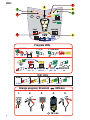 2
2
-
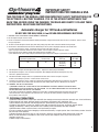 3
3
-
 4
4
-
 5
5
-
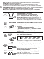 6
6
-
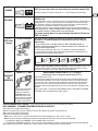 7
7
-
 8
8
-
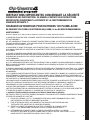 9
9
-
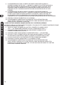 10
10
-
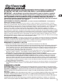 11
11
-
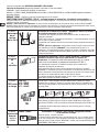 12
12
-
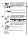 13
13
-
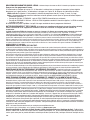 14
14
-
 15
15
-
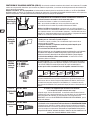 16
16
-
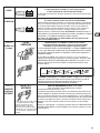 17
17
-
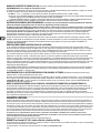 18
18
-
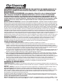 19
19
-
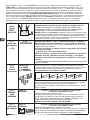 20
20
-
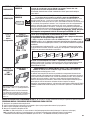 21
21
-
 22
22
-
 23
23
-
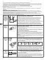 24
24
-
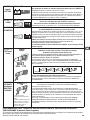 25
25
-
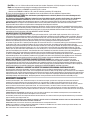 26
26
-
 27
27
-
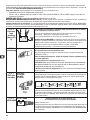 28
28
-
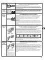 29
29
-
 30
30
-
 31
31
-
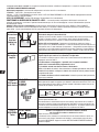 32
32
-
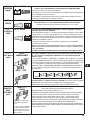 33
33
-
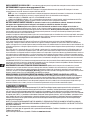 34
34
-
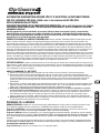 35
35
-
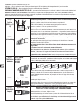 36
36
-
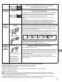 37
37
-
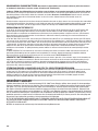 38
38
-
 39
39
-
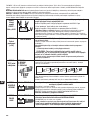 40
40
-
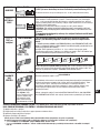 41
41
-
 42
42
-
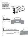 43
43
-
 44
44


Tecmate TM-34x OptiMate 4 Dual Program Manuale del proprietario
- Categoria
- Caricabatterie
- Tipo
- Manuale del proprietario
in altre lingue
- français: Tecmate TM-34x OptiMate 4 Dual Program Le manuel du propriétaire
- español: Tecmate TM-34x OptiMate 4 Dual Program El manual del propietario
- Deutsch: Tecmate TM-34x OptiMate 4 Dual Program Bedienungsanleitung
- Nederlands: Tecmate TM-34x OptiMate 4 Dual Program de handleiding
- português: Tecmate TM-34x OptiMate 4 Dual Program Manual do proprietário
Documenti correlati
-
Tecmate TM-180 OptiMate 6 Ampmatic Manuale del proprietario
-
-
-
-
-
-
Tecmate OptiMATE Lithium TM298 Manuale del proprietario
-
-