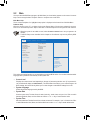
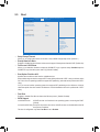
Gigabyte GA-SBCAP3455 Manuale del proprietario
- Categoria
- Schede madri
- Tipo
- Manuale del proprietario

GA-SBCAP3455
User's Manual
Rev. 1001
To reduce the impacts on global warming, the packaging materials of this product
are recyclable and reusable. GIGABYTE works with you to protect the environment.
For more product details, please visit GIGABYTE's website.

Copyright
© 2020 GIGA-BYTE TECHNOLOGY CO., LTD. All rights reserved.
The trademarks mentioned in this manual are legally registered to their respective owners.
Disclaimer
Information in this manual is protected by copyright laws and is the property of GIGABYTE.
Changes to the specications and features in this manual may be made by GIGABYTE without
prior notice. No part of this manual may be reproduced, copied, translated, transmitted, or
published in any form or by any means without GIGABYTE's prior written permission.
In order to assist in the use of this product, carefully read the User's Manual.
For product-related information, check on our website at: https://www.gigabyte.com
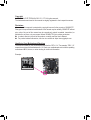
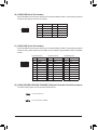
Identifying Your Motherboard Revision
The revision number on your motherboard looks like this: "REV: X.X." For example, "REV: 1.0"
means the revision of the motherboard is 1.0. Check your motherboard revision before updating
motherboard BIOS, drivers, or when looking for technical information.
Example:

- 3 -
Table of Contents
GA-SBCAP3455 Motherboard Layout ............................................................................. 4
Chapter 1 Hardware Installation .....................................................................................5
1-1 Installation Precautions .................................................................................... 5
1-2 ProductSpecications ...................................................................................... 6
1-3 Installing the Memory ....................................................................................... 8
1-4 Installing an Expansion Card ........................................................................... 8
1-5 Back Panel Connectors .................................................................................... 8
1-6 Internal Connectors ........................................................................................ 10
Chapter 2 BIOS Setup ..................................................................................................20
2-1 Startup Screen ............................................................................................... 20
2-2 Main ............................................................................................................... 21
2-3 Advanced ....................................................................................................... 22
2-4 Security .......................................................................................................... 27
2-5 Boot ................................................................................................................ 29
2-6 Save & Exit ..................................................................................................... 31
Chapter 3 Appendix ......................................................................................................32
Drivers Installation ..................................................................................................... 32
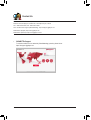
Regulatory Notices .................................................................................................... 33
Contact Us ................................................................................................................ 34

- 4 -
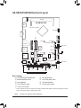
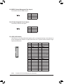
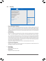
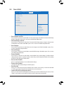
GA-SBCAP3455 Motherboard Layout
* The box contents above are for reference only and the actual items shall depend on the product package you obtain.
The box contents are subject to change without notice.
Box Contents
5GA-SBCAP3455 motherboard 5Two SATA cables
5Motherboard driver disc 5One SATA power cable
5User's Manual 5One heat spreader
5One COM port cable 5One DC power cable
5One LPT port cable
(Note) This chip is on the back of the motherboard.
HDMI
LVDS
BAT
B_BIOS (Note)
SYS_FAN
COMA COMC
SATA3 0 1
FPD
F_PANEL
GPIO_PWRSEL
CODEC
SPEAKER
CI
iTE®
Super I/O (Note)
F_USB1
F_USB2
2W_SPKR
CLR_CMOS
BL_SW
COMDCOMB
LAN1
SATA_PWR1
R_USB30
COMA_PW COMB_PW COMC_PW COMD_PW
SODIMM_1
VGA
Intel® Celeron® J3455E (Note)
LAN2
HP_MIC
MPCIE1
MSATA_MPCIE2
HS_2BHS_2A
HS_1BHS_1A
Realtek® GbE LAN
M_BIOS (Note)
LPT_SEL
U_SIM
GPIO_SET
LCD_VCC
MON_SW
SPEAKER_CONTROL
SMBUS
I2C
DCIN_PWR
LPT_GPIO SATA_PWR2
BIOS_SET
GA-SBCAP3455
TPM

- 5 -
Chapter 1 Hardware Installation
1-1 Installation Precautions
The motherboard contains numerous delicate electronic circuits and components which can become
damaged as a result of electrostatic discharge (ESD). Prior to installation, carefully read the user's
manual and follow these procedures:
•Prior to installation, make sure the chassis is suitable for the motherboard.
•Prior to installation, do not remove or break motherboard S/N (Serial Number) sticker or
warranty sticker provided by your dealer. These stickers are required for warranty validation.
•Always remove the AC power by unplugging the power cord from the power outlet before
installing or removing the motherboard or other hardware components.
•When connecting hardware components to the internal connectors on the motherboard, make
sure they are connected tightly and securely.
•When handling the motherboard, avoid touching any metal leads or connectors.
•It is best to wear an electrostatic discharge (ESD) wrist strap when handling electronic
components such as a motherboard, CPU or memory. If you do not have an ESD wrist strap,
keepyourhandsdryandrsttouchametalobjecttoeliminatestaticelectricity.
•Prior to installing the motherboard, please have it on top of an antistatic pad or within an
electrostatic shielding container.
•Before connecting or unplugging the power supply cable from the motherboard, make sure
the power supply has been turned off.
•Before turning on the power, make sure the power supply voltage has been set according to
the local voltage standard.
•Before using the product, please verify that all cables and power connectors of your hardware
components are connected.
•To prevent damage to the motherboard, do not allow screws to come in contact with the
motherboard circuit or its components.
•Make sure there are no leftover screws or metal components placed on the motherboard or
within the computer casing.
•Do not place the computer system on an uneven surface.
•Do not place the computer system in a high-temperature or wet environment.
•Turning on the computer power during the installation process can lead to damage to system
components as well as physical harm to the user.
•If you are uncertain about any installation steps or have a problem related to the use of the
product,pleaseconsultacertiedcomputertechnician.
•If you use an adapter, extension power cable, or power strip, ensure to consult with its installation
and/or grounding instructions.

- 6 -
1-2 ProductSpecications
CPU Built in with an Intel® Quad-Core Celeron® J3455E SoC (1.1 GHz~2.2 GHz)
* Do not disassemble the onboard SoC by yourself to avoid damage to these
components.
2 MB L2 Cache
Memory 1 x DDR3L SO-DIMM socket supporting up to 8 GB of system memory
Support for DDR3L 1866/1600/1333 MHz memory module
(Go to GIGABYTE's website for the latest supported memory speeds and memory
modules.)
Onboard
Graphics
Integrated in the SoC:
- 1 x D-Sub port, supporting a maximum resolution of 1920x1200@60 Hz
- 1 x HDMI port, supporting a maximum resolution of 3840x2160@30 Hz
Maximum shared memory of 512 MB
Audio Realtek® ALC255 codec
HighDenitionAudio
2-channel
LAN 2 x Realtek® GbE LAN chips (1000 Mbit/100 Mbit)
TPM Inneonchip,supportingTPM2.0
Expansion Slots 1 x half size Mini PCIe slot (MPCIE1)
(The Mini PCIe slot conforms to PCI Express 2.0 standard.)
Storage Interface Integrated in the SoC:
- 2 x SATA 6Gb/s connectors
- 1 x MSATA connector (MSATA_MPCIE2)
* The MSATA_MPCIE2 shares bandwidth with the SATA3 1 connector. The SATA3 1
becomes unavailable when a device is installed in the MSATA_MPCIE2 connector.
USB Integrated in the SoC:
- 2 x USB 3.0 ports on the back panel
- 4 x USB 2.0/1.1 ports available through the internal USB headers
Internal
Connectors
1 x DC-In power connector (DCIN_PWR)
1 x system fan header (SYS_FAN)
2 x SATA 6Gb/s connectors (SATA3 0/1)
2 x SATA power connectors (SATA_PWR1, SATA_PWR2)
1 x front panel header (F_PANEL)
1 x battery cable header (BAT)
2 x USB 2.0/1.1 headers (F_USB1, F_USB2)
4 x serial port headers (COMA/B/C/D)
4 x serial port power select jumpers (COMA/B/C/D_PW)
1 x speaker header (2W_SPKR)
1 x GPIO power selection jumper (GPIO_PWRSEL)
1xGPIOstatuscongurationjumper(GPIO_SET)
1 x LVDS header (LVDS)
1 x LVDS drive voltage jumper (LCD_VCC)
1xatpaneldisplayheader(FPD)
1xatpaneldisplayswitchheader(MON_SW)
1 x backlight switch header (BL_SW)
1 x volume control header (SPEAKER_CONTROL)
1 x buzzer header (SPEAKER)

- 7 -
Internal
Connectors
1 x LPT/GPIO header (LPT_GPIO)
1xLPTcongurationjumper(LPT_SEL)
1 x I2C jumper (I2C)
1 x SMBUS jumper (SMBUS)
1 x BIOS Select jumper (BIOS_SET)
1 x Clear CMOS jumper (CLR_CMOS)
1 x chassis intrusion header (CI)
Back Panel
Connectors
1 x HDMI port
1 x D-Sub port
2 x USB 3.0 ports
2 x RJ-45 ports
1 x audio jack (headphone and microphone combo jack)
I/O Controller iTE® I/O Controller Chip
Hardware
Monitor
Voltage detection
Temperature detection
Fan speed detection
Fan speed control
* Whether the fan speed control function is supported will depend on the cooler you
install.
BIOS 2x64Mbitash
Use of licensed AMI UEFI BIOS
Support for DualBIOS™
PnP 1.0a, DMI 2.7, WfM 2.0, SM BIOS 2.7, ACPI 5.0
Unique Features Support for Xpress Install
Support for @BIOS
Support for APP Center
* Available applications in APP Center may vary by motherboard model. Supported
functionsofeachapplicationmayalsovarydependingonmotherboardspecications
Bundled
Software Norton® Internet Security (OEM version)
Operating
System Support for Windows 10 64-bit
Form Factor SBC Form Factor; 14.6cm x 10.2cm
*GIGABYTEreservestherighttomakeanychangestotheproductspecicationsandproduct-relatedinformationwithout
prior notice.
Please visit GIGABYTE's website
for support lists of memory modules,
and SSDs.
Please visit the Support\Utility List
page on GIGABYTE's website to
download the latest version of apps.

- 8 -
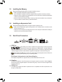
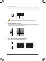
1-3 Installing the Memory
Read the following guidelines before you begin to install the memory:
•Make sure that the motherboard supports the memory.
(Go to GIGABYTE's website for the latest supported memory speeds and memory modules.)
•Always turn off the computer and unplug the power cord from the power outlet before installing the
memory to prevent hardware damage.
•Memory modules have a foolproof design. A memory module can be installed in only one direction.
If you are unable to insert the memory, switch the direction.
1-4 Installing an Expansion Card
Read the following guidelines before you begin to install an expansion card:
•Make sure the motherboard supports the expansion card. Carefully read the manual that came
with your expansion card.
•Always turn off the computer and unplug the power cord from the power outlet before installing an
expansion card to prevent hardware damage.
1-5 Back Panel Connectors
HDMI Port
The HDMI port is HDCP compliant and supports Dolby TrueHD and DTS HD
Master Audio formats. It also supports up to 192KHz/24bit 7.1-channel LPCM audio
output. You can use this port to connect your HDMI-supported monitor. The maximum supported resolution
is 3840x2160@30 Hz, but the actual resolutions supported are dependent on the monitor being used.
After installing the HDMI device, make sure to set the default sound playback device to HDMI. (The
item name may differ depending on your operating system.)
Dual-DisplayCongurationsfortheOnboardGraphics:
Dual-displaycongurationsaresupportedafteryouinstallmotherboarddriversinOS.
D-Sub Port
The D-Sub port supports a 15-pin D-Sub connector and supports a maximum resolution of 1920x1200@60 Hz
(the actual resolutions supported depend on the monitor being used). Connect a monitor that supports D-Sub
connection to this port.
USB 3.0 Port
The USB 3.0 port supports the USB 3.0specicationandiscompatibletotheUSB2.0specication.Use
this port for USB devices.

- 9 -
HP MIC (Headphone and Microphone Combo Jack)
This jack is for connecting a headphone or microphone. You can connect a microphone, headphone or
speaker to this jack.
•Whenremovingthecableconnectedtoabackpanelconnector,rstremovethecablefromyour
device and then remove it from the motherboard.
•When removing the cable, pull it straight out from the connector. Do not rock it side to side to
prevent an electrical short inside the cable connector.
Please visit GIGABYTE's website for more software information.
Activity LED Connection/
Speed LED
LAN Port Connection/Speed LED:
State Description
Orange 1 Gbps data rate
Green 100 Mbps data rate
Off 10 Mbps data rate
Activity LED:
State Description
Blinking Data transmission or receiving is occurring
Off No data transmission or receiving is occurring
RJ-45 LAN Port
The Gigabit Ethernet LAN port provides Internet connection at up to 1 Gbps data rate. The following
describes the states of the LAN port LEDs.

- 10 -
Read the following guidelines before connecting external devices:
•First make sure your devices are compliant with the connectors you wish to connect.
•Before installing the devices, be sure to turn off the devices and your computer. Unplug the power
cord from the power outlet to prevent damage to the devices.
•After installing the device and before turning on the computer, make sure the device cable has
been securely attached to the connector on the motherboard.
1-6 Internal Connectors
1) SYS_FAN
2) SATA3 0/1
3) SATA_PWR1/SATA_PWR2
4) BAT
5) F_PANEL
6) DCIN_PWR
7) F_USB1/F_USB2
8) SPEAKER_CONTROL
9) SPEAKER
10) 2W_SPKR
11) CI
12) MON_SW
13) LCD_VCC
14) GPIO_SET
15) BL_SW
16) FPD
17) GPIO_PWRSEL
18) LPT_GPIO
19) LPT_SEL
20) COMA/COMB
21) COMC/COMD
22) COMA/B/C/D_PW
23) SMBUS
24) I2C
25) LVDS
26) BIOS_SET
27) CLR_CMOS
28) USIM
2
3
1 28
9
4
5
6
7
8
10
11
12
13
14
15
16
1718 1920 2122
23
24
25
27
3
26

- 11 -
1) SYS_FAN (Fan Header)
The fan header on this motherboard is 4-pin. The fan header possesses a foolproof insertion design.
When connecting a fan cable, be sure to connect it in the correct orientation (the black connector wire is
the ground wire). The speed control function requires the use of a fan with fan speed control design. For
optimum heat dissipation, it is recommended that a system fan be installed inside the chassis.
•Be sure to connect fan cable to the fan header to prevent your system from overheating. Overheating may
result in damage to the system may hang.
•Thesefanheaderisnotcongurationjumperblocks.Donotplaceajumpercapontheheader.
Pin No. Denition
1 GND
2 +12V
3 Sense
4 VCC
DEBUG
PORT
G.QBOFM
1
Pin No. Denition
1 GND
2 TXP
3 TXN
4 GND
5 RXN
6 RXP
7 GND
2) SATA3 0/1 (SATA 6Gb/s Connectors)
The SATA connectors conform to SATA 6Gb/s standard and are compatible with SATA 3Gb/s and SATA 1.5Gb/s
standard. Each SATA connector supports a single SATA device.
DEBUG
PORT
G.QBOFM
1
7
DEBUG
PORT
G.QBOFM
3) SATA_PWR1/SATA_PWR2 (SATA Power Connectors)
The connectors provide power to the installed SATA devices.
eDP
1
SATA_PWR1
SATA_PWR1:
Pin No. Denition
1 VCC
2 GND
3 GND
4 +12V
SATA_PWR2:
Pin No. Denition
1 GND
2 VCC
3 +12V
4 GND
eDP
1
SATA_PWR2
1
0
SATA3

- 12 -
4) BAT/BAT_CON(Battery/BatteryPowerCableConnector)
Thebatteryprovidespowertokeepthevalues(suchasBIOScongurations,date,andtimeinformation)
in the CMOS when the computer is turned off. Replace the battery when the battery voltage drops to a low
level, or the CMOS values may not be accurate or may be lost.
5) F_PANEL (Front Panel Header)
Connect the power switch, reset switch, and system status indicator on the chassis to this header according
to the pin assignments below. Note the positive and negative pins before connecting the cables.
The front panel design may differ by chassis. A front panel module mainly consists of power switch, reset switch,
power LED, hard drive activity LED and etc. When connecting your chassis front panel module to this header,
make sure the wire assignments and the pin assignments are matched correctly.
•PW (Power Switch, Red):
Connectstothepowerswitchonthechassisfrontpanel.Youmaycongure
the way to turn off your system using the power switch.
•HD (Hard Drive Activity LED, Blue):
Connects to the hard drive activity LED on the chassis front panel. The
LED is on when the hard drive is reading or writing data.
•RES (Reset Switch, Green):
Connects to the reset switch on the chassis front panel. Press the reset
switch to restart the computer if the computer freezes and fails to perform
a normal restart.
•NC (Purple):
No connection.
•PLED (Power LED, Yellow):
Connects to the power status indicator on the
chassis front panel. The LED is on when the
system is operating. The LED is off when the
system is in S3/S4 sleep state or powered
off (S5).
System Status LED
S0 On
S3/S4/S5 Off
1
2
9
10
NC
PLED-
PW-
PLED+
PW+
HD-
RES+
HD+
RES-
Power Switch
Hard Drive
Activity LED
Reset Switch
Power LED
Pin No. Denition
1(+) RTC Power
2(-) GND
F_USB30 F_U
B_
F_ F_
_
B
BS_
B
SB_
B
_S
S_
_
B
_U
_
B
S
123
123
123
123
1
1
1
1
BSS
S
_S
SSU
1 2 3
S3 BSSS
U
__ 3
F_USB3F
S _
S _
S _
SF
B_
B_
F
_0
S
S
_0F
_F
_
_
__B
U
S _S
_ SF_
B
USB0_B
B_
B_
F_USB3
F_USB303
_
_3U
S_
2(-)
1(+)
You may clear the CMOS values by removing the battery cable:
1. Turn off your computer and unplug the power cord.
2. Unplug the the battery cable from the battery cable header and wait
for one minute.
3. Plug in the battery cable.
4. Plug in the power cord and restart your computer.
•Always turn off your computer and unplug the power cord before replacing the battery.
•Replace the battery with an equivalent one. Damage to your devices may occur if the battery is
replaced with an incorrect model.
•Contact the place of purchase or local dealer if you are not able to replace the battery by yourself
or uncertain about the battery model.
•Used batteries must be handled in accordance with local environmental regulations.

- 13 -
7) F_USB1/F_USB2 (USB 2.0/1.1 Headers)
TheheadersconformtoUSB2.0/1.1specication.EachUSBheadercanprovidetwoUSBportsviaan
optional USB bracket. For purchasing the optional USB bracket, please contact the local dealer.
Pin No. Denition Pin No. Denition
1 Power (5V) 6 USB DY+
2 Power (5V) 7 GND
3 USB DX- 8 GND
4 USB DY- 9 No Pin
5 USB DX+ 10 NC
•Do not plug the IEEE 1394 bracket (2x5-pin) cable into the USB header.
•Prior to installing the USB bracket, be sure to turn off your computer and unplug the power cord from the power
outlet to prevent damage to the USB bracket.
12
109
8) SPEAKER_CONTROL(VolumeControlHeader)
The header connects to the volume control button of the monitor to control the volume. This feature requires
a software update to be enabled.
Pin No. Denition
1 VOL_DW
2 GND
3 VOL_UP
1
9) SPEAKER (Buzzer Header)
Connects to the buzzer on the chassis front panel. The system reports system startup status by issuing a
beep code. One single short beep will be heard if no problem is detected at system startup.
Pin No. Denition
1 VCC
2 NC
3 NC
4 SPK-
DEBUG
PORT
G.QBOFM
1
6) DCIN_PWR (DC Power Connector, Input 9V ~ 36V)
Pin No. Denition
1 GND
2 DC IN
3 DC IN
4 GND
1
eDP

- 14 -
11) CI (Chassis Intrusion Header)
This motherboard provides a chassis detection feature that detects if the chassis cover has been removed.
This function requires a chassis with chassis intrusion detection design.
Pin No. Denition
1 Signal
2 GND
1
12) MON_SW(FlatPanelDisplaySwitchHeader)
This header allows you to connect an on/off switch for the display.
Pin No. Denition
1 Mon_SW
2 GND
1
13) LCD_VCC (LVDS Drive Voltage Jumper)
This jumper can be used to provide different screen voltage settings.
1-2 Close: Set to 3V. (Default)
2-3 Close: Set to 5V.
1
1
10) 2W_SPKR (Speaker Header)
This header provides a 2W (4ohm) speaker on your AIO chassis.
Pin No. Denition
1 SPK_LP
2 SPK_LN
1

- 15 -
15) BL_SW (Backlight Switch)
The backlight switch provides the function for screen backlight adjustment.
Pin No. Denition
1 BL_DOWN
2 BL_UP
1
16) FPD (Flat Panel Display Header)
The FPD is a high-speed interface connecting the output of a video controller in a laptop computer, computer
monitor or LCD television set to the display panel. Most laptops, LCD computer monitors and LCD TVs use
thisinterfaceinternally.TheheaderconformstoFPDspecication.
Pin No. Denition
1 BKLT_EN
2 BKLT_PWM
3 BKLT_PWR (FPD_PWR)
4 BKLT_PWR (FPD_PWR)
5 BKLT_GND/Brightness_GND
6 BKLT_GND/Brightness_GND
7 Brightness_Up
8 Brightness_Down
1
8
eDP
14) GPIO_SET(GPIOStatusCongurationJumper)
Use this jumper to set the GPIO status of the LPT_GPIO header to HIGH or LOW.
1-2 Close: Set to HIGH level (3V) (Default)
2-3 Close: Set to LOW level.
1
1

- 16 -
18) LPT_GPIO(LPT/GPIOHeader)
Use this header to connect a LPT or GPIO device. Refer to the descriptions of the LPT_SEL and GPIO_
PWRSELjumpersforfurtherconguration.
eDP
26
25
2
1
Pin No. Denition Pin No. Denition Pin No. Denition
1STB- 10 GND 19 ACK-
2AFD- 11 PD4 20 GND
3PD0 12 GND 21 BUSY
4ERR- 13 PD5 22 GND
5PD1 14 GND 23 PE
6INIT- 15 PD6 24 GND
7PD2 16 GND 25 SLCT
8SLIN- 17 PD7 26 No Pin
9PD3 18 GND
LPT:
Pin No. Denition Pin No. Denition Pin No. Denition
1SIO_GP87 10 GPIOPWR 19 SIO_GP83
2SIO_GP86 11 SIO_GP74 20 GND
3SIO_GP70 12 GPIOPWR 21 SIO_GP82
4NC 13 SIO_GP75 22 GND
5SIO_GP71 14 GND 23 SIO_GP81
6SIO_GP85 15 SIO_GP76 24 GND
7SIO_GP72 16 GND 25 SIO_GP80
8SIO_GP84 17 SIO_GP77 26 No Pin
9SIO_GP73 18 GND
GPIO:
19) LPT_SEL(LPTCongurationJumper)
PlacethejumpercaponthetwopinstoconguretheLPT_GPIOheadertosupportLPTdevice.Note:If
the jumper cap is removed from this jumper, be sure to place it on the GPIO_PWRSEL pins.
Short:ConguretheLPT_GPIOheadertosupportLPTdevice.(Default)
1
17) GPIO_PWRSEL(GPIOPowerSelectionJumper)
MovethejumpercapfromtheLPT_SELjumpertothisjumpertoconguretheLPT_GPIOheadertosupport
GPIO device and also to specify the GPIO voltage.
1-2 Close: Set GPIO voltage to +12V.
2-3 Close: Set GPIO voltage to 5V.
1
1

- 17 -
22) COMA_PW/COMB_PW/COMC_PW/COMD_PW(SerialPortHeaderPowerSelectJumpers)
The power select jumpers are used to select serial port power.
1-2 Close: Set to 12V.
2-3 Close: Set to 5V. (Default)
1
1
21) COMC/COMD(SerialPortHeaders)
Each COM header can provide one serial port via an optional COM port cable. For purchasing the optional
COM port cable, please contact the local dealer. The two headers support RS232, RS422, and RS485
devices.
Pin No. Denition
1 NDCD-
2 NDSR-
3 NSIN
4 NRTS-
5 NSOUT
6 NCTS-
7 NDTR-
8 +5V/+12V
9 GND
10 NC
For RS232 Devices:
Pin No. Denition
1 TX(B)
2 NC
3 TX(A)
4 NC
5 RX(A)
6 NC
7 RX(B)
8 +5V/+12V
9 GND
10 NC
For RS422 Devices:
Pin No. Denition
1 D-
2 NC
3 D+
4 NC
5 NC
6 NC
7 NC
8 +5V/+12V
9 GND
10 NC
For RS485 Devices:
10
eDP
9
2
1
20) COMA/COMB(SerialPortHeaders)
Each COM header can provide one serial port via an optional COM port cable. For purchasing the optional
COM port cable, please contact the local dealer.
Pin No. Denition Pin No. Denition
1 NDCD- 6 NCTS-
2 NDSR- 7 NDTR-
3 NSIN 8 12V_5V
4 NRTS- 9 GND
5 NSOUT 10 NC
10
eDP
9
2
1

- 18 -
25) LVDS (LVDS Header)
LVDS stands for Low-voltage differential signaling, which uses high-speed analog circuit techniques to
provide multigigabit data transfers on copper interconnects and is a generic interface standard for high-
speed data transmission.
Pin No. Denition Pin No. Denition
1 LCD_VCC 21 -RXE0_C
2 LCD_VCC 22 +RXE0_C
3 VCC3 23 GND
4 NC 24 -RXE1_C
5 NC 25 +RXE1_C
6 -RXO0_C 26 GND
7 +RXO0_C 27 -RXE2_C
8 GND 28 +RXE2_C
9 -RXO1_C 29 CABLE_DET (Note)
10 +RXO1_C 30 -RXE3_C
11 GND 31 +RXE3_C
12 -RXO2_C 32 GND
13 +RXO2_C 33 -RXECLKE_C
14 GND 34 +RXECLKE_C
15 -RXO3_C 35 GND
16 +RXO3_C 36 SC_BKLT_EN
17 GND 37 SC_BKLT_CTL
18 -RXECLKO_C 38 FPD_PWR
19 +RXECLKO_C 39 FPD_PWR
20 GND 40 FPD_PWR
(Note) Connects to Pin 35 and the ground pin of the LVDS.
eDP
21
4039
24) I2C (Inter-Integrated Circuit Jumper)
This header provides the I2C signals.
Pin No. Denition
1 I2C_SCL
2 I2C_SDA
3 GND
1
23) SMBUS (System Management Bus Jumper)
This header provides the SMBUS signals.
Pin No. Denition
1 SMB_CLK
2 SMB_DATA
3 GND
1

- 19 -
27) CLR_CMOS(ClearCMOSJumper)
UsethisjumpertocleartheBIOScongurationandresettheCMOSvaluestofactorydefaults.Toclear
the CMOS values, use a metal object like a screwdriver to touch the two pins for a few seconds.
•Always turn off your computer and unplug the power cord from the power outlet before clearing the CMOS values.
•After system restart, go to BIOS Setup to load factory defaults (select Load Optimized Defaults) or manually
conguretheBIOSsettings.
Open: Normal
Short: Clear CMOS Values
26) BIOS_SET(BIOSSelectJumper)
The jumper allows users to easily select a different BIOS for boot up.
1-2 Close: M_BIOS (Boot from the main BIOS) (Default)
2-3 Close: B_BIOS (Boot from the backup BIOS)
1
1
28) USIM (USIM Connector)
This connector can be used to install a Micro Sim card to connect to a mini PCIe LAN card.

- 20 -
Chapter2 BIOSSetup
2-1 Startup Screen
The following startup Logo screen will appear whe`n the computer boots.
BIOS (Basic Input and Output System) records hardware parameters of the system in the CMOS on the
motherboard. Its major functions include conducting the Power-On Self-Test (POST) during system startup,
saving system parameters and loading operating system, etc. BIOS includes a BIOS Setup program that allows
theusertomodifybasicsystemcongurationsettingsortoactivatecertainsystemfeatures.
When the power is turned off, the battery on the motherboard supplies the necessary power to the CMOS to
keepthecongurationvaluesintheCMOS.
To access the BIOS Setup program, press the <Delete> key during the POST when the power is turned on.
To upgrade the BIOS, use the GIGABYTE @BIOS utility, which is a Windows-based utility that searches and
downloads the latest version of BIOS from the Internet and updates the BIOS.
•BecauseBIOSashingispotentiallyrisky,ifyoudonotencounterproblemsusingthecurrentversionofBIOS,
itisrecommendedthatyounotashtheBIOS.ToashtheBIOS,doitwithcaution.InadequateBIOSashing
may result in system malfunction.
•It is recommended that you not alter the default settings (unless you need to) to prevent system instability or other
unexpected results. Inadequately altering the settings may result in system's failure to boot. If this occurs, try to
clear the CMOS values and reset the board to default values. (Refer to the "Load Optimized Defaults" section in
this chapter or introductions of the battery/clear CMOS jumper in Chapter 1 for how to clear the CMOS values.)
La pagina si sta caricando...
La pagina si sta caricando...
La pagina si sta caricando...
La pagina si sta caricando...
La pagina si sta caricando...
La pagina si sta caricando...
La pagina si sta caricando...
La pagina si sta caricando...
La pagina si sta caricando...
La pagina si sta caricando...
La pagina si sta caricando...
La pagina si sta caricando...
La pagina si sta caricando...
La pagina si sta caricando...
-
 1
1
-
 2
2
-
 3
3
-
 4
4
-
 5
5
-
 6
6
-
 7
7
-
 8
8
-
 9
9
-
 10
10
-
 11
11
-
 12
12
-
 13
13
-
 14
14
-
 15
15
-
 16
16
-
 17
17
-
 18
18
-
 19
19
-
 20
20
-
 21
21
-
 22
22
-
 23
23
-
 24
24
-
 25
25
-
 26
26
-
 27
27
-
 28
28
-
 29
29
-
 30
30
-
 31
31
-
 32
32
-
 33
33
-
 34
34


Gigabyte GA-SBCAP3455 Manuale del proprietario
- Categoria
- Schede madri
- Tipo
- Manuale del proprietario
in altre lingue
- English: Gigabyte GA-SBCAP3455 Owner's manual
Documenti correlati
-
Gigabyte GA-IMBLAP3455 Manuale del proprietario
-
-
-
-
-
-
Gigabyte H510M H Manuale del proprietario
-
-