
User Manuals
LtAP mini (RB912R-2nD-LTm)
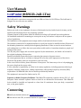
The LtAP mini is a wireless access point with two SIM card slots for 3G/LTE data. The LtAP mini is
designed for use with your own modem.
Safety Warnings
Before you work on any equipment, be aware of the hazards involved with electrical circuitry, and be
familiar with standard practices for preventing accidents.
Ultimate disposal of this product should be handled according to all national laws and regulations.
All installation methods for mounting an access point on any wall surface is subject to the acceptance
of local jurisdiction.
The Installation of the equipment must comply with local and national electrical codes.
This product is intended to be mounted outdoors on a pole but can also be installed indoors. Please read
the mounting instructions carefully before beginning installation. Failure to use the correct hardware
and configuration or to follow the correct procedures could result in a hazardous situation to people and
damage to the system.
Use only the power supply and accessories approved by the manufacturer, and which can be found in
the original packaging of this product.
Read the installation instructions before connecting the system to the power source.
We cannot guarantee that no accidents or damage will occur due to the improper use of the device.
Please use this product with care and operate at your own risk!
In the case of device failure, please disconnect it from power. The fastest way to do so is by unplugging
the power plug from the power outlet.
It is the customer's responsibility to follow local country regulations, including operation within legal
frequency channels, output power, cabling requirements, and Dynamic Frequency Selection (DFS)
requirements. All Mikrotik radio devices must be professionally installed.
The equipment is not tested for Outdoor use by UL.
Exposure to Radio Frequency Radiation: This MikroTik equipment complies with the FCC, IC, and
European Union radiation exposure limits set forth for an uncontrolled environment. This MikroTik
device should be installed and operated no closer than 20 centimeters from your body, occupational
user, or the general public.
Connecting
Install your desired modem (see "miniPCIe slot usage").
If the intent to use GPS, an external antenna is required (see "GPS usage").

Choose your powering solution (see "Powering").
Connect your Internet cable to the Ethernet port.
Set your computer IP configuration to automatic (DHCP).
Connect your direct input power jack if not using PoE, to start up the device.
The device will boot up and the Wireless network will be available for connecting.
Open network connections on your PC, mobile phone, or other device and search for MikroTik
wireless network and connect to it.
Once connected to the wireless network, open in your web browser to start
configuration, since there is no password by default, you will be logged in automatically (or, for some
models, check user and wireless passwords on the sticker). The configuration also can be done using a
mobile app (see "MikroTik mobile app"), and WinBox configuration tool https://mt.lv/winbox.
We recommend clicking the "Check for updates" button and updating your RouterOS software to the
latest version to ensure the best performance and stability.
Choose your country, to apply country regulation settings, and set up your password on the screen
that loads.
*The following RouterOS "npk" packages are required for the core functionality of the product: gps,
system.
Mounting
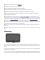
1.It is possible to attach the device to a wall, using the provided screw holes on the sides of the unit.
The device should be mounted in a way that the cable openings are pointing downward as shown in the
picture.
2.The ports are protected with a small door, that is held in place with one screw. Use the Philips PH2
screwdriver to access the ports.
3.The door has cut-out places for all available ports, but please only break out the openings that you
will use. The device can be used both indoors and outdoors. The IP rating scale for this device is IP54.

4.The device enclosure has places where you can drill openings for external LTE and GPS antennas.
Use a drill to make holes that are appropriate for the antenna cable used.
Alternatively, you can obtain a "DINrail Pro" - mounting bracket, designed to fit standard 35 mm x 7.5
mm DIN rails. https://mikrotik.com/product/dinrail_pro
When mounting outdoors, please ensure that any cable openings are directed downwards. Use a PoE
injector and proper grounding. Recommended using Cat6 cable.
Warning! This equipment should be installed and operated with a minimum distance of 20 cm between
the device and your body. The operation of this equipment in the residential environment could cause
radio interference.
The mounting and configuration of this device should be done by a qualified person.
Powering
All voltages are in compliance with ES1 and max. PS2/LPS according to EN IEC 62368-1.
Input
Voltage
DC plug: 8-30
VDC
USB: 5 VDC
PoE: 8-57 VDC
Input
Power 9W
Direct-input power jack (5.5 mm outside and 2 mm inside, female, pin positive plug) accepts 8-30 V
DC.
microUSB port accepts 5 V powering.
Ethernet port accepts passive and 802.3af/at Power over Ethernet 8-57 V DC (compensate for loss on
cable, so more than 12 V recommended).

The power consumption under maximum load with attachments can reach 9 W.
Connecting to a PoE Adapter:
1.Connect the Ethernet cable from the device to the PoE+DATA port of the PoE adapter.
2.Connect an Ethernet cable from your local network (LAN) to the PoE adapter.
3.Connect the power cord to the adapter, and then plug the power cord into a power outlet.
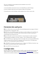
Extension slots and ports
Built-in 2 GHz wireless access point module, AP/station/bridge/p2p modes are supported. Onboard
PIF antennas built-in. Antenna gain1.5 dBi.
miniPCIe slot and two SIM slots (can't be used without a modem installed, can't be used both at the
same time) to be used with a 3G/4G/LTE modem. Onboard antennas available, but openings for
external antennas are provided on the case.
Built-in GPS module - uFL connector provided for an external antenna. To enable, set the port to
serial0 (this disables the DB9 port on the unit). Supports - GPS, GLONASS, BeiDou, Galileo).
One 10/100 Ethernet port, supporting automatic cross/straight cable correction (Auto MDI/X). Either
straight or crossover cable can be used for connecting to other network devices. The Ethernet port
accepts 12-57 V DC powering from a passive PoE injector.
One DB9 RS232 serial port for serial console access. Configured as 115200 bit/s, 8 data bits, 1 stop
bit, no parity. Can't be used if built-in GPS is enabled on serial0.
One microUSB 2.0 port for powering only.
Configuration
RouterOS includes many configuration options in addition to what is described in this document. We
suggest starting here to get yourself accustomed to the possibilities: https://mt.lv/help. In case IP
connection is not available, the Winbox tool (https://mt.lv/winbox) can be used to connect to the MAC

address of the device from the LAN side (all access is blocked from the internet port by default).
For recovery purposes, it is possible to boot the device from the network, see section Buttons and
jumpers.
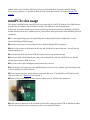
miniPCIe slot usage
The device is equipped with a miniPCIe slot to be used with a 3G/4G/LTE modem. Two SIM slots are
provided for use together with a miniPCIe modem. The SIM slot is not used separately.
In this case, an internal antenna is not connected (located inside the enclosure). Installing a miniPCIe
module should be done by a qualified person, please follow safety precautions when handling electrical
equipment:
Use a wrist grounding strap when unpacking and working with electrical components to avoid
electrical discharge (ESD) damage.
Open the front cover by unscrewing one screw with the Philips PH2 screwdriver.
Remove four screws on the bottom of the case and lift off the top part of the case. You will see the
antenna attached to it.
Locate the mini PCIe slot on the PCB and remove two factory attached screws.
Attach provided a thick thermal pad to the card, and install the card into miniPCIe slot so that the
thermal pad is between PCB and card.
The secure card in place using previously removed two screws.
Attach the grey uFL connector to the MAIN antenna connector of the modem, attach the black cable
to the secondary (or AUX) connector.
To use external antennas, attach antenna connectors and use a 6.5 mm drill bit to drill holes on the
side of the unit. (see "Mounting") description 4.
Please see the picture below on how to place rubber seals for the best water protection.
Attach antenna connectors to the installed card and GPS connector on the PCB, as additional rubber
silicone can be used to secure connectors in place on card and PCB board.

Attach a thinner thermal pad to the top of the card.
Reassembly in backorder.
After you have reinserted the device into the case and secured it with the screws that were removed
earlier, slide in the SIM cards from your mobile operator into the SIM slots, with the chips facing as
shown on the port label. The slot accepts miniSIM (2FF). Close the black latch for SIM cards, to secure
them in the slots.
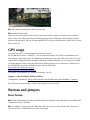
GPS usage
In order to use GPS, an external antenna is needed to connect.
We recommend to use the "ACGPSA" - can be obtained separately. ACGPSA is a standalone active
GPS antenna, that works in the 1575.4 MHz spectrum. Antenna size is 46.5 mm x 26.5 mm x 12.5 mm
with an IP67 rating and includes an internal magnet and double-sided tape, so it can easily be attached
to various surfaces. It has a long 5m cable with an SMA connector, to be connected to LtAP mini via
the ACSMAUFL pigtail (not included, product code ACSMAUFL)
https://mikrotik.com/product/acgpsa
https://mikrotik.com/product/acsmaufl
To connect a GPS antenna, see "miniPCIe slot usage" step 10.
Supports - GPS, GLONASS, BeiDou, Galileo).
Configuration information - https://wiki.mikrotik.com/wiki/Manual:System/GPS#Basic_examples
The GPS uses an active antenna, connect only when power is turned off.
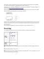
Buttons and jumpers
Reset button
Hold this button during boot time until LED light starts flashing, release the button to reset RouterOS
configuration (total 5 seconds).
Keep holding for 5 more seconds, LED turns solid, release now to turn on CAP mode. The device
will now look for a CAPsMAN server (total 10 seconds).

Or keep holding the button for 5 more seconds until LED turns off, then release it to make the
RouterBOARD look for Netinstall servers (total 15 seconds).
Regardless of the above option used, the system will load the backup RouterBOOT loader if the button
is pressed before power is applied to the device. Useful for RouterBOOT debugging and recovery.
Mode button
The action of the mode buttons can be configured from RouterOS software to execute any user-
supplied RouterOS script. You can also disable this button. The mode button can be configured in
RouterOS menu /system routerboard mode-button
Accessories
Package includes the following accessories that come with the device:
⎓DC Switching Power Supply 24 V, 1.2 A, 28.8 W, 86.8 %, VI, cable:220 cm RA DC.
⎓Cable DC plug RA 5.5x2.1x10.5 to Striped 2*24 AWG Tin 8 mm, length 0.35 m.
PoE Injector with shielded Ethernet cable/connector (RBPoE).
⎓DC 24 V 1.2 A power adapter.
Mounting kit K-55 VMS.
Elastic thermal pad, 25x40x3.5 mm.
Specifications
For more information about this product, specification and pictures please visit our web
page: https://mikrotik.com/product/ltap_mini
Operating system support
The device supports RouterOS software version 6. The specific factory-installed version number is
indicated in the RouterOS menu /system resource. Other operating systems have not been tested.
MikroTik mobile app
Use the MikroTik smartphone app to configure your router in the field, or to apply the most basic initial
settings for your MikroTik home access point.

1.Scan QR code and choose your preferred OS.
2.Install and open application.
3.By default, the IP address and user name will be already entered.
4.Click Connect to establish a connection to your device through a wireless network.
5.Choose Quick setup and application will guide you through all basic configuration settings in a
couple of easy steps.
6.An advanced menu is available to fully configure all necessary settings.
To avoid pollution of the environment, please separate the device from household waste and dispose of
it in a safe manner, such as in designated waste disposal sites. Familiarize yourself with the procedures
for the proper transportation of the equipment to the designated disposal sites in your area.
Federal Communication Commission
Interference Statement
Model FCCID
RB912R-2nD-
LTm
TV7RB912R-
2NDLTM
This equipment has been tested and found to comply with the limits for a Class B digital device,
pursuant to Part 15 of the FCC Rules. These limits are designed to provide reasonable protection
against harmful interference in a residential installation.
This equipment generates, uses, and can radiate radio frequency energy and, if not installed and used
in accordance with the instructions, may cause harmful interference to radio communications.
However, there is no guarantee that interference will not occur in a particular installation. If this
equipment does cause harmful interference to radio or television reception, which can be determined
by turning the equipment off and on, the user is encouraged to try to correct the interference by one of
the following measures:
Reorient or relocate the receiving antenna.

Increase the separation between the equipment and receiver.
Connect the equipment into an outlet on a circuit different from that to which the receiver is
connected.
Consult the dealer or an experienced radio/TV technician for help.
FCC Caution: Any changes or modifications not expressly approved by the party responsible for
compliance could void the user's authority to operate this equipment.
This device complies with Part 15 of the FCC Rules. Operation is subject to the following two
conditions: (1) This device may not cause harmful interference, and (2) this device must accept any
interference received, including interference that may cause undesired operation. This device and its
antenna must not be co-located or operation in conjunction with any other antenna or transmitter.
IMPORTANT: Exposure to Radio Frequency Radiation.
This equipment complies with the FCC RF radiation exposure limits set forth for an uncontrolled
environment. This equipment should be installed and operated with a minimum distance of 20 cm
between the radiator and any part of your body.
Innovation, Science and Economic Development
Canada
Model IC
RB912R-2nD-
LTm
7442A-
912R2NDLTM
This device complies with Industry Canada's licence-exempt RSS standard(s). Operation is subject to
the following two conditions: (1) this device may not cause interference, and (2) this device must
accept any interference, including interference that may cause undesired operation of the device.
Le présent appareil est conforme aux CNR d'Industrie Canada applicables aux appareils radio exempts
de licence. L'exploitation est autorisée aux deux conditions suivantes : (1) l'appareil ne doit pas
produire de brouillage, et (2) l'utilisateur de l'appareil doit accepter tout brouillage radioélectrique subi,
même si le brouillage est susceptible d'en compromettre le fonctionnement.
This Class B digital apparatus complies with Canadian ICES-003.
Cet appareil numérique de la classe [B] est conforme à la norme NMB-003 du Canada.
CAN ICES-003 (B) / NMB-003 (B)
IMPORTANT: Exposure to Radio Frequency Radiation.
This equipment complies with the IC radiation exposure limits set forth for an uncontrolled
environment. This equipment should be installed and operated with a minimum distance of 20 cm
between the radiator and any part of your body.
Cet équipement est conforme aux limites d'exposition au rayonnement IC définies pour un
environnement non contrôlé. Cet équipement doit être installé et utilisé à une distance minimale de 20
cm entre le radiateur et toute partie de votre corps.

UKCA marking
Eurasian Conformity Mark
Частотный диапазон Мощность передатчика
2400-2483.5 МГц ≤100 мВт
*Доступные частотные каналы могут различаться в зависимости от модели продукта и
сертификации.
Информация о дате изготовления устройства указана в конце серийного номера на его наклейке
через дробь. Первая цифра означает номер года (последняя цифра года), две последующие
означают номер недели.
Изготовитель: Mikrotikls SIA, Aizkraukles iela 23, Riga, LV-1006, Латвия, [email protected].
Сделано в Китае, Латвии или Литве. Cм. на упаковке.
Для получения подробных сведений о гарантийном обслуживании обратитесь к продавцу.
Информация об импортерах продукции MikroTik в Российскую
Федерацию: https://mikrotik.com/buy/europe/russia
Продукты MikroTik, которые поставляются в Евразийский таможенный союз, оцениваются с
учетом соответствующих требований и помечены знаком EAC, как показано ниже:
Norma Oficial Mexicana
Rango de frecuencia (potencia de salida máxima): 2400-2483.5 MHz (30 dBm). Los canales de
frecuencia disponibles pueden variar según el modelo y la certificación del producto.
EFICIENCIA ENERGETICA CUMPLE CON LA NOM-029-ENER-2017.
La operacion de este equipo esta sujeta a las siguientes dos condiciones:
Es posible que este equipo o dispositivo no cause interferencia perjudicial y.

Este equipo debe aceptar cualquier interferencia, incluyendo la que pueda causar su operacion no
deseada.
Fabricante: Mikrotikls SIA, Brivibas gatve 214i, Riga, LV-1039, Latvia.
País De Origen: Letonia; Lituania; China (Republica Popular); Estados Unidos De America; Mexico.
Por favor contacte a su distribuidor local para preguntas regionales específicas. La lista de
importadores se puede encontrar en nuestra página de inicio
–https://mikrotik.com/buy/latinamerica/mexico.
The National Commission for the State
Regulation of Communications and
Informatization by Ukraine
Виробник: Mikrotikls SIA, Brivibas gatve 214i Рига, Латвія, LV1039.
Робоча частота (Максимальна вихідна потужність): 2480-2483.5 МГц (20 дБм).
Справжнім Mikrotikls SIA заявляє, що маршрутизатор відповідає основним вимогам та іншим
відповідним положенням директиви 2014/53/EC, а також суттєвим вимогам Технічного
регламенту радіообладнання, затвердженого постановою Кабінету Міністрів України від 24
травня 2017 року № 355.
Для експлуатації в Україні необхідно отримати дозвіл на експлуатацію у порядку, затвердженому
рішенням НКРЗІ від 01.11.2012 № 559, зареєстрованому в Міністерстві юстиції України
03.01.2013 за № 57/22589.
CE Declaration of Conformity
Manufacturer: Mikrotikls SIA, Brivibas gatve 214i Riga, Latvia, LV1039.
Hereby, Mikrotīkls SIA declares that the radio equipment type RB912R-2nD-LTm is in compliance
with Directive 2014/53/EU. The full text of the EU declaration of conformity is available at the
following internet address: https://mikrotik.com/products
Frequency bands terms of use
Frequency range (for
applicable models)
Channels
used
Maximum Output
Power (EIRP) Restriction
2400-2483.5 MHz 1 - 13 20 dBm Without any restriction to use in

all EU Member States
* It is the customer's responsibility to follow local country regulations, including operation within legal
frequency channels, output power, cabling requirements, and Dynamic Frequency Selection (DFS)
requirements. All MikroTik radio devices must be professionally installed!
This MikroTik device meets Maximum WLAN transmit power limits per ETSI regulations. For more
detailed information see Declaration of Conformity above / Dieses MikroTik-Gerät erfüllt die
maximalen WLAN- Sendeleistung Grenzwerte gemäß ETSI-Bestimmungen. Weitere Informationen
finden Sie oben unter Konformitätserklärung / Cet appareil MikroTik respecte les limites maximales de
puissance de transmission WLAN conformément aux réglementations ETSI. Pour plus d'informations,
voir la déclaration de conformité ci-dessus / Questo dispositivo MikroTik è conforme ai limiti massimi
di potenza di trasmissione WLAN in conformità con le normative ETSI. Per ulteriori informazioni,
consultare la dichiarazione di conformità sopra / Este dispositivo MikroTik cumple con los límites
máximos de potencia de transmisión WLAN de acuerdo con las regulaciones ETSI. Para obtener más
información, consulte la declaración de conformidad anterior / Это устройство MikroTik
соответствует максимальным пределам мощности передачи WLAN в соответствии с правилами
ETSI. Для получения дополнительной информации см. Декларацию соответствия выше.
Note. The information contained here is subject to change. Please visit the product page
on www.mikrotik.com for the most up to date version of this document.
-
 1
1
-
 2
2
-
 3
3
-
 4
4
-
 5
5
-
 6
6
-
 7
7
-
 8
8
-
 9
9
-
 10
10
-
 11
11
-
 12
12


in altre lingue
- English: MikroTik LtAP mini User manual
Documenti correlati
-
MikroTik RB750r2 hEX Lite Guida utente
-
MikroTik CAPGI-5HAXD2HAXD Guida utente
-
-
-
-
MikroTik CRS109 Guida utente
-
MikroTik CUBEG-5AC60AY Manuale utente
-
-
MikroTik hEX S Manuale utente
-
MikroTik RB5009UG+S+IN Routers and Wireless Manuale utente