Blaupunkt RVC 4.1 KH Manuale del proprietario
- Tipo
- Manuale del proprietario

REAR VIEW CAMERA
RVC 4.1 KH | RVC 4.2 W | RVC 4.3 U | RVC 4.4 A
Enjoy it.
DE Bedienungsanleitung
EN Owner’s manual
PL Instrukcja obsługi
FR Mode d’emploi
ES Manual de instrucciones
IT Manuale di istruzioni

MONTAGE
Montageort des Universaltyps
1. Achten Sie darauf,
dass die verwendete
Lochsäge den gleichen
Durchmesser wie die
Kamera hat.
2. Positionieren Sie die
Kamera so, dass die
Pfeilmarkierung nach
oben zeigt.
3. Führen Sie den Kabel-
baum durch das im
Stoßfänger angebrach-
te Loch, bevor Sie die
Kamera montieren.
4. Setzen Sie die Kamera in
das Loch ein und drücken
Sie sie mit zwei Daumen
gleichmäßig nach unten,
damit sie fest und ach sitzt.
Montageort des Sondertyps
A. Montageanleitung für die Kamera bündig mit der Stoßfängeroberäche
Gleicher Durchmesser

DE
MONTAGE
1. Wählen Sie eine ache
Stelle nahe der Kenn-
zeichenbeleuchtung
und bohren Sie ein
kleines Loch für die
erste Schraube.
3. Schließen Sie das
Strom- und das Video-
kabel an, und positio-
nieren Sie die Kamera
so, dass die zweite
Schraube entspre-
chend dem Kamerabild
auf dem Bildschirm an
der besten Stelle ange-
bracht werden kann.
2. Drehen Sie die erste
Schraube mit einem
Schraubendreher ein
(nicht bis zum An-
schlag).
4. Markieren Sie die
Stelle für die zweite
Schraube und bohren
Sie das Loch.
5. Drehen Sie die zweite
Schraube mit einem
Schraubenzieher ein.
B. Montageanleitung für eine an der Halterung montierte Kamera
Hinweis:
Zusätzlich zu den bündig und an der Halterung montierten Kameras bieten wir auch
Kameras für die Schraubmontage an, die wie folgt montiert werden:
1. Wählen Sie eine geeignete ache Stelle in der Nähe der Kennzeichenbeleuchtung
und markieren Sie diese.
2. Bohren Sie ein Loch mit demselben Durchmesser wie die Schraube.
3. Führen Sie die Schraube senkrecht (zum Boden) in das Loch ein und befestigen Sie
sie mit der von innen eingeführten Schraube.
4. Einige Modelle sind mit einem Bildumschalter nach oben/unten ausgestattet und
können so montiert werden, dass sich die Schraube in einer horizontalen Position
(zum Boden) bendet und das Objektiv nach unten gerichtet ist.

TECHNISCHE DATEN
SCHALTPLAN
Video-Signal CVBS Stromaufnahme < 40 mA
Signal NTSC Leistung < 0,35 W
Eektive Pixelanzahl 688X528 Wasserdichtheits-
klasse
IP67
Spannung DC 12 V
Betriebstemperaturbereich
-20 °C ~
+65 °C
Min. Lichtstärke 0,1 Lux Lagertemperatur-
bereich
-30 °C ~
+80 °C
Zusätzliche Aus-
stattung
VK-RVC 4.X (10 m Verlängerungskabel RCA);
SF-RVC 4.X (Signallter)
Sonstiges Rückansicht mit Parklinie, Form-/Spiegelschalter,
Parklinienschalter, Doppelspulen-Steuerfunktion
Achten Sie beim
Anschließen auf die
Pfeilmarkierung
EEqquuaall DDiiaammeetteerr
UUPP
UUPP
B. Installation Guide For Bracket-Mount Camera
Blue loop: Cut to switch to front view
Purple or white loop: Cut to turn off parking line
Switch Loop Instructions:
Wiring Diagram
Remarks:
Beside flush and bracket mount cameras, we also
have bolt mount camera series, which is mounted
by following steps:
1. Select suitable flat position near the license plate light and mark it.
2. Drill a hole according to the bolt diameter.
3. Put the bolt vertically (against ground) into the hole and fix the bolt
with the screw supplied from inside.
4. Some models come with up/down image switch option, and can be
mounted with its bolt horizontal (against ground) and its lens
downward.
1.Choose a flat position near license
plate light and make a small hole
for the first screw with a drill.
2. Use a screw driver to fix the first
screw (but not tightly).
3. Get the power/video cables connected,
and then adjust the camera properly to find
the best position for the other screw
according to the camera image in monitor.
4. Mark the position found for second
screw and make a hole with a drill.
5. Fix the second screw with a
screw driver.
A. Installation Guide For Flush-Mount Camera
B
A
1.Check to be sure the hole saw
used is with equal diameter to
that of camera.
2. Adjust the camera to turn the
UP arrow mark straight upwards.
3. Put the harness through the
hole made on bumper before
fixing the camera.
4. Put the camera into the hole and
use your two thumbs to press it
evenly for tight and flat mounting.
B
A
Special type installation locationUniversal type installation location
Parameters
Current
Consumption
Power
Waterproof Grade
Operating
temperature range
Other
Optional accessories
-20℃ ~ +65℃
VK-RVC 4.X (10 meter RCA extension cable); SF-RVC 4.X (signal filter)
Rear view with parking line, formal/ mirror switch, parking line swich, dual-coil control dual
functions
Video signal
Signal
Effective Pixels
Voltage
Min Illumination
CVBS
NTSC
DC12V
0.1 Lux
688X528
<40mA
IP67
Storage
temperature range -30℃ ~ +80℃
<0.35W
Kamera
an den
RCA-Video-
eingang des
Bildschirms
Netzteil
Rotes Kabel für
Rückfahrscheinwerfer (+12 V)
Schwarzes Kabel für Masse
Der Schaltplan gilt für die meis-
ten (aber nicht alle) Kamera-
modelle und Sie sollten beim
Herstellen der Verbindungen
auch auf die Beschriftungen
oder Markierungen an den
Kabeln achten.
LCD-Display Kamera für
Rückfahrschein-
werfer für Masse

DE
OPTIONEN
Parklinie: bei einigen Modellen verfügbar, siehe Abbildung oben.
Diese Option kann durch Befolgen der Anweisungen für die Schaltschleife
aktiviert werden.
Schalter Spiegel/rechtes Bild: Für einige Modelle verfügbar.
Diese Option kann durch Befolgen der Anweisungen für die Schaltschleife
aktiviert werden.
Schalter Bild oben/unten: Bei einigen Modellen mit Schraubbefestigung erhältlich.
Diese Option kann durch Befolgen der Anweisungen für die Schaltschleife
aktiviert werden.
Anweisungen für die Schaltschleife:
Blaue Schleife: Schneiden, um zur Vorderansicht zu wechseln
Lilafarbene oder weiße Schleife: Schneiden, um die Parklinie zu deaktivieren
Kamerabild ohne Parklinie Kamerabild mit Parklinie
EEqquuaall DDiiaammeetteerr
UUPP
UUPP
B. Installation Guide For Bracket-Mount Camera
Blue loop: Cut to switch to front view
Purple or white loop: Cut to turn off parking line
Switch Loop Instructions:
Wiring Diagram
Remarks:
Beside flush and bracket mount cameras, we also
have bolt mount camera series, which is mounted
by following steps:
1. Select suitable flat position near the license plate light and mark it.
2. Drill a hole according to the bolt diameter.
3. Put the bolt vertically (against ground) into the hole and fix the bolt
with the screw supplied from inside.
4. Some models come with up/down image switch option, and can be
mounted with its bolt horizontal (against ground) and its lens
downward.
1.Choose a flat position near license
plate light and make a small hole
for the first screw with a drill.
2. Use a screw driver to fix the first
screw (but not tightly).
3. Get the power/video cables connected,
and then adjust the camera properly to find
the best position for the other screw
according to the camera image in monitor.
4. Mark the position found for second
screw and make a hole with a drill.
5. Fix the second screw with a
screw driver.
A. Installation Guide For Flush-Mount Camera
B
A
1.Check to be sure the hole saw
used is with equal diameter to
that of camera.
2. Adjust the camera to turn the
UP arrow mark straight upwards.
3. Put the harness through the
hole made on bumper before
fixing the camera.
4. Put the camera into the hole and
use your two thumbs to press it
evenly for tight and flat mounting.
B
A
Special type installation locationUniversal type installation location
Parameters
Current
Consumption
Power
Waterproof Grade
Operating
temperature range
Other
Optional accessories
-20℃ ~ +65℃
VK-RVC 4.X (10 meter RCA extension cable); SF-RVC 4.X (signal filter)
Rear view with parking line, formal/ mirror switch, parking line swich, dual-coil control dual
functions
Video signal
Signal
Effective Pixels
Voltage
Min Illumination
CVBS
NTSC
DC12V
0.1 Lux
688X528
<40mA
IP67
Storage
temperature range -30℃ ~ +80℃
<0.35W
Kamera
Vebindungsschleife
EEqquuaall DDiiaammeetteerr
UUPP
UUPP
B. Installation Guide For Bracket-Mount Camera
Blue loop: Cut to switch to front view
Purple or white loop: Cut to turn off parking line
Switch Loop Instructions:
Wiring Diagram
Remarks:
Beside flush and bracket mount cameras, we also
have bolt mount camera series, which is mounted
by following steps:
1. Select suitable flat position near the license plate light and mark it.
2. Drill a hole according to the bolt diameter.
3. Put the bolt vertically (against ground) into the hole and fix the bolt
with the screw supplied from inside.
4. Some models come with up/down image switch option, and can be
mounted with its bolt horizontal (against ground) and its lens
downward.
1.Choose a flat position near license
plate light and make a small hole
for the first screw with a drill.
2. Use a screw driver to fix the first
screw (but not tightly).
3. Get the power/video cables connected,
and then adjust the camera properly to find
the best position for the other screw
according to the camera image in monitor.
4. Mark the position found for second
screw and make a hole with a drill.
5. Fix the second screw with a
screw driver.
A. Installation Guide For Flush-Mount Camera
B
A
1.Check to be sure the hole saw
used is with equal diameter to
that of camera.
2. Adjust the camera to turn the
UP arrow mark straight upwards.
3. Put the harness through the
hole made on bumper before
fixing the camera.
4. Put the camera into the hole and
use your two thumbs to press it
evenly for tight and flat mounting.
B
A
Special type installation locationUniversal type installation location
Parameters
Current
Consumption
Power
Waterproof Grade
Operating
temperature range
Other
Optional accessories
-20℃ ~ +65℃
VK-RVC 4.X (10 meter RCA extension cable); SF-RVC 4.X (signal filter)
Rear view with parking line, formal/ mirror switch, parking line swich, dual-coil control dual
functions
Video signal
Signal
Effective Pixels
Voltage
Min Illumination
CVBS
NTSC
DC12V
0.1 Lux
688X528
<40mA
IP67
Storage
temperature range -30℃ ~ +80℃
<0.35W

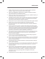
1. Einige Funktionen, die in dieser Bedienungsanleitung beschrieben werden, sind
modellspezisch und werden möglicherweise nicht von jedem Modell unterstützt.
2. Nehmen Sie keine Änderungen oder Manipulationen am Gerät vor. Das Gerät enthält
keine Teile, die von Ihnen selbst repariert werden können.
3. Die Leistungsgrenzen des Geräts müssen beachtet werden. Lassen Sie die Reparatur
und gegebenenfalls die Montage von einem Fachmann durchführen.
4. Die Eigenmontage ist nur dann ratsam, wenn Sie Erfahrung in der Montage solcher
Geräte haben und mit der elektrischen Anlage des Fahrzeugs vertraut sind. Beachten
Sie die Markierungen auf den Anschlüssen.
5. Stellen Sie sicher, dass alle Drähte die richtigen Signale und Spannungen übermitteln.
6. Beim Einbau des Radios darf die Aktivierung der Airbags und anderer
sicherheitsrelevanter Einrichtungen oder Bedienelemente nicht beeinträchtigt oder
verhindert werden.
7. Klemmen Sie die Fahrzeugbatterie (Minuspol, Masse) ab, bevor Sie das Gerät
einbauen, da es sonst zu Fehlfunktionen oder Beschädigungen des Gerätes oder der
Fahrzeugelektronik kommen kann. Beachten Sie die Sicherheitsempfehlungen des
Fahrzeugherstellers (Airbags, Alarmanlage, Bordcomputer, Wegfahrsperre usw.).
8. Die Rückfahrkamera (Frontkamera) ist ein technisches Gerät mit einer
Fahrerassistenzfunktion. Dies bedeutet nicht, dass der Fahrer von seiner
Verantwortung beim Fahren befreit ist.
9. Damit die Kamera/der Bildschirm ordnungsgemäß funktioniert, sollten Sie sie
regelmäßig von Schmutz, Wassertropfen, Schnee usw. befreien.
10. Obwohl die Kamera wasserdicht ist, darf sie NICHT mit einem Hochdruckwasserstrahl
gereinigt werden, da dies zu Rissen im Glasobjektiv führen kann.
11. Bringen Sie die Kamera-/Bildschirmkabel nicht in die Nähe von Objekten mit hohen
Temperaturen, wie z. B. einem Motor oder einer Auspuanlage.
12. Wenn Ihr Kameramodell nicht über eine eingebaute LED-Beleuchtung verfügt,
schalten Sie die Kennzeichenbeleuchtung ein, um nachts oder in dunklen Bereichen
besser gesehen zu werden.
13. Die Kamera/der Bildschirm kann mit Fahrzeugen mit einer Ausgangsleistung von 12
V DC betrieben werden (10 % weniger oder mehr Ausgangsleistung ist zulässig). Das
Modell 5.1 darf NICHT in Fahrzeugen mit einer Ausgangsleistung von 24 V DC oder
einer anderen Ausgangsleistung außerhalb dieses Bereichs montiert werden, da die
Gefahr besteht, dass die Anlage durchbrennt.
14. Die technischen Daten der Kamera/des Bildschirms können ohne vorherige
Ankündigung geändert werden.
WICHTIGE HINWEISE

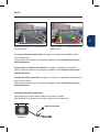
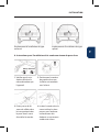
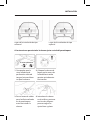
INSTALLATION
EN
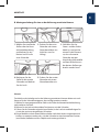
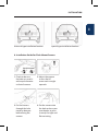
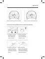
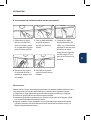
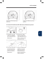
Universal type installation location
1. Check to be sure
the hole saw used is
with equal diameter
to that of camera.
2. Adjust the camera
to turn the UP
arrow mark straight
upwards.
3. Put the harness
through the hole
made on bumper
before xing the
camera.
4. Put the camera into
the hole and use your
two thumbs to press
it evenly for tight and
at mounting.
Special type installation location
A. Installation Guide For Flush-Mount Camera
Equal Diameter

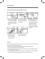
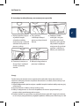
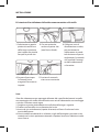
INSTALLATION
1. Choose a at position
near license plate light
and make a small hole
for the rst screw with
a drill.
3. Get the power/video
cables connected, and
then adjust the camera
properly to nd the
best position for the
other screw according
to the camera image in
monitor.
2. Use a screw driver to
x the rst screw (but
not tightly).
4. Mark the position
found for second
screw and make a
hole with a drill.
5. Fix the second screw
with a screw driver.
B. Installation Guide For Bracket-Mount Camera
Remarks:
Beside ush and bracket mount cameras, we also have bolt mount camera series,
which is mounted by following steps:
1. Select suitable at position near the license plate light and mark it.
2. Drill a hole according to the bolt diameter.
3. Put the bolt vertically (against ground) into the hole and x the bolt with the
screw supplied from inside.
4. Some models come with up/down image switch option, and can be mounted
with its bolt horizontal (against ground) and its lens downward.

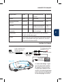
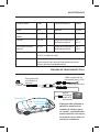
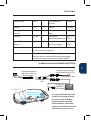
PARAMETERS
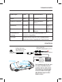
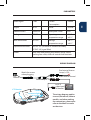
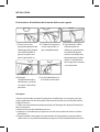
WIRING DIAGRAM
EN
Video signal CVBS Current
Consumption
<40mA
Signal NTSC Power <0.35W
Eective Pixels 688X528 Waterproof Grade IP67
Voltage DC12V Operating
temperature range
-20 °C ~
+65 °C
Min Illumination 0.1 Lux Storage
temperature range
-30 °C ~
+80 °C
Optional accessories VK-RVC 4.X (10 meter RCA extension cable);
SF-RVC 4.X (signal lter)
Other Rear view with parking line, formal/ mirror switch,
parking line swich, dual-coil control dual functions
Watch the arrows
when plugging
EEqquuaall DDiiaammeetteerr
UUPP
UUPP
B. Installation Guide For Bracket-Mount Camera
Blue loop: Cut to switch to front view
Purple or white loop: Cut to turn off parking line
Switch Loop Instructions:
Wiring Diagram
Remarks:
Beside flush and bracket mount cameras, we also
have bolt mount camera series, which is mounted
by following steps:
1. Select suitable flat position near the license plate light and mark it.
2. Drill a hole according to the bolt diameter.
3. Put the bolt vertically (against ground) into the hole and fix the bolt
with the screw supplied from inside.
4. Some models come with up/down image switch option, and can be
mounted with its bolt horizontal (against ground) and its lens
downward.
1.Choose a flat position near license
plate light and make a small hole
for the first screw with a drill.
2. Use a screw driver to fix the first
screw (but not tightly).
3. Get the power/video cables connected,
and then adjust the camera properly to find
the best position for the other screw
according to the camera image in monitor.
4. Mark the position found for second
screw and make a hole with a drill.
5. Fix the second screw with a
screw driver.
A. Installation Guide For Flush-Mount Camera
B
A
1.Check to be sure the hole saw
used is with equal diameter to
that of camera.
2. Adjust the camera to turn the
UP arrow mark straight upwards.
3. Put the harness through the
hole made on bumper before
fixing the camera.
4. Put the camera into the hole and
use your two thumbs to press it
evenly for tight and flat mounting.
B
A
Special type installation locationUniversal type installation location
Parameters
Current
Consumption
Power
Waterproof Grade
Operating
temperature range
Other
Optional accessories
-20℃ ~ +65℃
VK-RVC 4.X (10 meter RCA extension cable); SF-RVC 4.X (signal filter)
Rear view with parking line, formal/ mirror switch, parking line swich, dual-coil control dual
functions
Video signal
Signal
Effective Pixels
Voltage
Min Illumination
CVBS
NTSC
DC12V
0.1 Lux
688X528
<40mA
IP67
Storage
temperature range -30℃ ~ +80℃
<0.35W
Camera
to RCA
video input
of Monitor
Power adaptor
Red wire to Reverse
Lamp (+12V)
Black wire to Ground
The wiring diagram applies
to most (but not all) camera
models, and when making
the connections, please also
refer to the labels or marks
on the wires.
LCD Monitor
to Ground
to reverse light
Camera

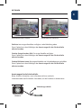
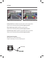
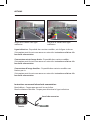
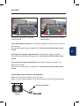
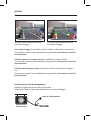
OPTIONS
Parking Guide Line: Available on partial models, refer to image above.
Option can be realized by following Switch Loop Instructions.
Mirror/right image switch: Available on partial models.
Option can be realized by following Switch Loop Instructions.
Up/down image switch: Available on partial bolt mount type models.
Option can be realized by following Switch Loop Instructions.
Switch Loop Instructions:
Blue loop: Cut to switch to front view
Purple or white loop: Cut to turn o parking line
Camera Image w/o parking guide line Camera image with parking guide line
EEqquuaall DDiiaammeetteerr
UUPP
UUPP
B. Installation Guide For Bracket-Mount Camera
Blue loop: Cut to switch to front view
Purple or white loop: Cut to turn off parking line
Switch Loop Instructions:
Wiring Diagram
Remarks:
Beside flush and bracket mount cameras, we also
have bolt mount camera series, which is mounted
by following steps:
1. Select suitable flat position near the license plate light and mark it.
2. Drill a hole according to the bolt diameter.
3. Put the bolt vertically (against ground) into the hole and fix the bolt
with the screw supplied from inside.
4. Some models come with up/down image switch option, and can be
mounted with its bolt horizontal (against ground) and its lens
downward.
1.Choose a flat position near license
plate light and make a small hole
for the first screw with a drill.
2. Use a screw driver to fix the first
screw (but not tightly).
3. Get the power/video cables connected,
and then adjust the camera properly to find
the best position for the other screw
according to the camera image in monitor.
4. Mark the position found for second
screw and make a hole with a drill.
5. Fix the second screw with a
screw driver.
A. Installation Guide For Flush-Mount Camera
B
A
1.Check to be sure the hole saw
used is with equal diameter to
that of camera.
2. Adjust the camera to turn the
UP arrow mark straight upwards.
3. Put the harness through the
hole made on bumper before
fixing the camera.
4. Put the camera into the hole and
use your two thumbs to press it
evenly for tight and flat mounting.
B
A
Special type installation locationUniversal type installation location
Parameters
Current
Consumption
Power
Waterproof Grade
Operating
temperature range
Other
Optional accessories
-20℃ ~ +65℃
VK-RVC 4.X (10 meter RCA extension cable); SF-RVC 4.X (signal filter)
Rear view with parking line, formal/ mirror switch, parking line swich, dual-coil control dual
functions
Video signal
Signal
Effective Pixels
Voltage
Min Illumination
CVBS
NTSC
DC12V
0.1 Lux
688X528
<40mA
IP67
Storage
temperature range -30℃ ~ +80℃
<0.35W
Camera
switch loop
EEqquuaall DDiiaammeetteerr
UUPP
UUPP
B. Installation Guide For Bracket-Mount Camera
Blue loop: Cut to switch to front view
Purple or white loop: Cut to turn off parking line
Switch Loop Instructions:
Wiring Diagram
Remarks:
Beside flush and bracket mount cameras, we also
have bolt mount camera series, which is mounted
by following steps:
1. Select suitable flat position near the license plate light and mark it.
2. Drill a hole according to the bolt diameter.
3. Put the bolt vertically (against ground) into the hole and fix the bolt
with the screw supplied from inside.
4. Some models come with up/down image switch option, and can be
mounted with its bolt horizontal (against ground) and its lens
downward.
1.Choose a flat position near license
plate light and make a small hole
for the first screw with a drill.
2. Use a screw driver to fix the first
screw (but not tightly).
3. Get the power/video cables connected,
and then adjust the camera properly to find
the best position for the other screw
according to the camera image in monitor.
4. Mark the position found for second
screw and make a hole with a drill.
5. Fix the second screw with a
screw driver.
A. Installation Guide For Flush-Mount Camera
B
A
1.Check to be sure the hole saw
used is with equal diameter to
that of camera.
2. Adjust the camera to turn the
UP arrow mark straight upwards.
3. Put the harness through the
hole made on bumper before
fixing the camera.
4. Put the camera into the hole and
use your two thumbs to press it
evenly for tight and flat mounting.
B
A
Special type installation locationUniversal type installation location
Parameters
Current
Consumption
Power
Waterproof Grade
Operating
temperature range
Other
Optional accessories
-20℃ ~ +65℃
VK-RVC 4.X (10 meter RCA extension cable); SF-RVC 4.X (signal filter)
Rear view with parking line, formal/ mirror switch, parking line swich, dual-coil control dual
functions
Video signal
Signal
Effective Pixels
Voltage
Min Illumination
CVBS
NTSC
DC12V
0.1 Lux
688X528
<40mA
IP67
Storage
temperature range -30℃ ~ +80℃
<0.35W

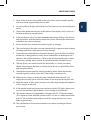
1. Some of the functions described in the instructions may be model-specic
and may not be supported by every model.
2. Do not modify or tamper with the device. There are no user-serviceable parts
inside.
3. Observe the performance limits of the device. Have repairs and, if necessary,
installation done by a professional.
4. Install the device only if you have needed experience installing such devices
and are familiar with the vehicle’s electrical system. Observe the information
marked on the unit connections.
5. Ensure that all wires transfer the correct signals or voltages.
6. The installation of the radio must not interfere with or prevent the activation
of airbags and other safety devices and/or controls.
7. Disconnect the vehicle battery (negative terminal, ground) before installing
the device, as doing otherwise may cause malfunctions or damage to the
device or the vehicle electronics. Observe the vehicle manufacturer’s safety
instructions (airbag, alarm system, on-board computer, immobiliser, etc.).
8. The rear (front) view camera functions technically as a driver assistance
device, which cannot be taken as substitute for driver’s responsibility when
operating the vehicle.
9. To keep the camera/monitor working properly, please clean the camera/
monitor regularly to free it from dirt, water drops, snowdrops etc.
10. Although the camera is designed to be waterproof, please do NOT use
high-pressure water jet to wash the camera as this may break the glass lens.
11. Keep the cables of the camera/monitor away from high temperature objects
such as engine or exhaust.
12. If the camera model you have comes without in-built LED lights, please turn
on your license plate light for better vision at night or in dark areas.
13. The camera/monitor are applicable to vehicles with DC 12V power output
(10 % higher or lower allowed), please do NOT use the 5.1 model on vehicles
with DC 24V or other power output out of this range, otherwise it is very
likely to get burned.
14. The specications of the camera/monitor are subject to change without
prior notice.
IMPORTANT NOTES
EN

INSTALACJA
Miejsce instalacji typu uniwersalnego
1. Sprawdzić, czy użyta
otwornica ma taką
samą średnicę jak
średnica kamery.
2. Ustawić kamerę tak,
aby znak strzałki w
górę był skierowany
pionowo w górę.
3. Przełożyć wiązkę prze-
wodów przez otwór
wykonany w zderzaku
przed zamocowaniem
kamery.
4. Włożyć kamerę do
otworu i dwoma kciukami
docisnąć ją równomiernie
w celu uzyskania mocnego
i płaskiego mocowania.
Miejsce instalacji typu specjalnego
A. Instrukcja instalacji kamery równo z powierzchnią zderzaka
Taka sama średnica

PL
INSTALACJA
1. Wybrać płaskie miejsce
w pobliżu lampki
oświetlenia tablicy
rejestracyjnej i wykonać
wiertłem mały otwór na
pierwszy wkręt.
3. Podłączyć kable
zasilające i wizyjne,
a następnie ustawić
kamerę w taki sposób,
aby znaleźć najlepsze
miejsce na drugi wkręt
zgodnie z obrazem z
kamery na monitorze.
2. Przy pomocy
śrubokręta wkręcić
pierwszy wkręt (nie do
końca).
4. Zaznaczyć miejsce na
drugi wkręt i wykonać
otwór za pomocą
wiertła.
5. Wkręcić drugi wkręt za
pomocą śrubokręta.
B. Instrukcja instalacji kamery mocowanej na wsporniku
Uwagi:
Oprócz kamer do montażu równo z powierzchnią zderzaka i kamer do montażu na
wsporniku, oferujemy również serię kamer do montażu na śrubach, które montuje się w
następujący sposób:
1. Wybrać odpowiednie, płaskie miejsce w pobliżu lampki oświetlenia tablicy rejestracyjnej
i zaznaczyć je.
2. Wywiercić otwór o średnicy równej średnicy śruby.
3. Włożyć śrubę pionowo (w stosunku do podłoża) do otworu i przymocować ją za
pomocą wkrętu przełożonego od wewnątrz.
4. Niektóre modele są wyposażone w przełącznik obrazu góra/dół i mogą być montowa-
ne ze śrubą w pozycji poziomej (względem podłoża) i obiektywem skierowanym w dół.

DANE TECHNICZNE
SCHEMAT POŁĄCZEŃ ELEKTRYCZNYCH
Sygnał wideo CVBS Pobór prądu <40mA
Sygnał NTSC Moc <0,35W
Efektywna liczba
pikseli
688X528 Klasa
wodoszczelności
IP67
Napięcie DC12V Zakres temperatury
roboczej
-20 °C ~
+65 °C
Min. natężenie
światła
0,1 lux Zakres temperatury
przechowywania
-30 °C ~
+80 °C
Wyposażenie dodat-
kowe
VK-RVC 4.X (10-metrowy kabel przedłużający RCA);
SF-RVC 4.X (ltr sygnału)
Pozostałe Widok do tyłu z linią parkowania, przełącznik formal-
ny/lusterka, przełącznik linii parkowania, podwójna
funkcja sterowania podwójną cewką
Zwrócić uwagę na
strzałki podczas
podłączania
EEqquuaall DDiiaammeetteerr
UUPP
UUPP
B. Installation Guide For Bracket-Mount Camera
Blue loop: Cut to switch to front view
Purple or white loop: Cut to turn off parking line
Switch Loop Instructions:
Wiring Diagram
Remarks:
Beside flush and bracket mount cameras, we also
have bolt mount camera series, which is mounted
by following steps:
1. Select suitable flat position near the license plate light and mark it.
2. Drill a hole according to the bolt diameter.
3. Put the bolt vertically (against ground) into the hole and fix the bolt
with the screw supplied from inside.
4. Some models come with up/down image switch option, and can be
mounted with its bolt horizontal (against ground) and its lens
downward.
1.Choose a flat position near license
plate light and make a small hole
for the first screw with a drill.
2. Use a screw driver to fix the first
screw (but not tightly).
3. Get the power/video cables connected,
and then adjust the camera properly to find
the best position for the other screw
according to the camera image in monitor.
4. Mark the position found for second
screw and make a hole with a drill.
5. Fix the second screw with a
screw driver.
A. Installation Guide For Flush-Mount Camera
B
A
1.Check to be sure the hole saw
used is with equal diameter to
that of camera.
2. Adjust the camera to turn the
UP arrow mark straight upwards.
3. Put the harness through the
hole made on bumper before
fixing the camera.
4. Put the camera into the hole and
use your two thumbs to press it
evenly for tight and flat mounting.
B
A
Special type installation locationUniversal type installation location
Parameters
Current
Consumption
Power
Waterproof Grade
Operating
temperature range
Other
Optional accessories
-20℃ ~ +65℃
VK-RVC 4.X (10 meter RCA extension cable); SF-RVC 4.X (signal filter)
Rear view with parking line, formal/ mirror switch, parking line swich, dual-coil control dual
functions
Video signal
Signal
Effective Pixels
Voltage
Min Illumination
CVBS
NTSC
DC12V
0.1 Lux
688X528
<40mA
IP67
Storage
temperature range -30℃ ~ +80℃
<0.35W
Kamera
do wejścia
wideo RCA
monitora
Zasilacz sieciowy
Przewód czerwony do
lampy cofania (+12V)
Przewód czarny do masy
Schemat połączeń dotyczy
większości (ale nie wszyst-
kich) modeli kamery, a pod-
czas wykonywania połączeń
należy również zwracać
uwagę na etykiety lub oznac-
zenia na przewodach.
Wyświetlacz
LCD Kamera do
lampy cofania
do masy

PL
OPCJE
Linia prowadząca do parkowania: Dostępna w niektórych modelach, patrz
ilustracja powyżej.
Opcję tę można zrealizować, postępując zgodnie z instrukcjami dotyczącymi
pętli przełączania.
Przełącznik lusterka/prawego obrazu: Dostępny w niektórych modelach.
Opcję tę można zrealizować, postępując zgodnie z instrukcjami dotyczącymi
pętli przełączania.
Przełącznik obrazu góra/dół: Dostępny w niektórych modelach z mocowaniem
przy pomocy śruby.
Opcję tę można zrealizować, postępując zgodnie z instrukcjami dotyczącymi
pętli przełączania.
Instrukcja dla pętli łączeniowej:
Pętla niebieska: Przeciąć, aby przełączyć na widok z przodu
Pętla oletowa lub biała: Przeciąć, aby wyłączyć linię parkowania
Obraz z kamery bez linii prowadzącej
do parkowania
Obraz z kamery z linią prowadzącą do
parkowania
EEqquuaall DDiiaammeetteerr
UUPP
UUPP
B. Installation Guide For Bracket-Mount Camera
Blue loop: Cut to switch to front view
Purple or white loop: Cut to turn off parking line
Switch Loop Instructions:
Wiring Diagram
Remarks:
Beside flush and bracket mount cameras, we also
have bolt mount camera series, which is mounted
by following steps:
1. Select suitable flat position near the license plate light and mark it.
2. Drill a hole according to the bolt diameter.
3. Put the bolt vertically (against ground) into the hole and fix the bolt
with the screw supplied from inside.
4. Some models come with up/down image switch option, and can be
mounted with its bolt horizontal (against ground) and its lens
downward.
1.Choose a flat position near license
plate light and make a small hole
for the first screw with a drill.
2. Use a screw driver to fix the first
screw (but not tightly).
3. Get the power/video cables connected,
and then adjust the camera properly to find
the best position for the other screw
according to the camera image in monitor.
4. Mark the position found for second
screw and make a hole with a drill.
5. Fix the second screw with a
screw driver.
A. Installation Guide For Flush-Mount Camera
B
A
1.Check to be sure the hole saw
used is with equal diameter to
that of camera.
2. Adjust the camera to turn the
UP arrow mark straight upwards.
3. Put the harness through the
hole made on bumper before
fixing the camera.
4. Put the camera into the hole and
use your two thumbs to press it
evenly for tight and flat mounting.
B
A
Special type installation locationUniversal type installation location
Parameters
Current
Consumption
Power
Waterproof Grade
Operating
temperature range
Other
Optional accessories
-20℃ ~ +65℃
VK-RVC 4.X (10 meter RCA extension cable); SF-RVC 4.X (signal filter)
Rear view with parking line, formal/ mirror switch, parking line swich, dual-coil control dual
functions
Video signal
Signal
Effective Pixels
Voltage
Min Illumination
CVBS
NTSC
DC12V
0.1 Lux
688X528
<40mA
IP67
Storage
temperature range -30℃ ~ +80℃
<0.35W
Kamera
pętla łączeniowa
EEqquuaall DDiiaammeetteerr
UUPP
UUPP
B. Installation Guide For Bracket-Mount Camera
Blue loop: Cut to switch to front view
Purple or white loop: Cut to turn off parking line
Switch Loop Instructions:
Wiring Diagram
Remarks:
Beside flush and bracket mount cameras, we also
have bolt mount camera series, which is mounted
by following steps:
1. Select suitable flat position near the license plate light and mark it.
2. Drill a hole according to the bolt diameter.
3. Put the bolt vertically (against ground) into the hole and fix the bolt
with the screw supplied from inside.
4. Some models come with up/down image switch option, and can be
mounted with its bolt horizontal (against ground) and its lens
downward.
1.Choose a flat position near license
plate light and make a small hole
for the first screw with a drill.
2. Use a screw driver to fix the first
screw (but not tightly).
3. Get the power/video cables connected,
and then adjust the camera properly to find
the best position for the other screw
according to the camera image in monitor.
4. Mark the position found for second
screw and make a hole with a drill.
5. Fix the second screw with a
screw driver.
A. Installation Guide For Flush-Mount Camera
B
A
1.Check to be sure the hole saw
used is with equal diameter to
that of camera.
2. Adjust the camera to turn the
UP arrow mark straight upwards.
3. Put the harness through the
hole made on bumper before
fixing the camera.
4. Put the camera into the hole and
use your two thumbs to press it
evenly for tight and flat mounting.
B
A
Special type installation locationUniversal type installation location
Parameters
Current
Consumption
Power
Waterproof Grade
Operating
temperature range
Other
Optional accessories
-20℃ ~ +65℃
VK-RVC 4.X (10 meter RCA extension cable); SF-RVC 4.X (signal filter)
Rear view with parking line, formal/ mirror switch, parking line swich, dual-coil control dual
functions
Video signal
Signal
Effective Pixels
Voltage
Min Illumination
CVBS
NTSC
DC12V
0.1 Lux
688X528
<40mA
IP67
Storage
temperature range -30℃ ~ +80℃
<0.35W

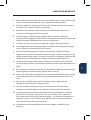
1. Niektóre z funkcji opisanych w instrukcji mogą występować tylko w wybranych
modelach i mogą nie być obsługiwane przez wszystkie modele.
2. Zabrania się modykowania i ingerowania w urządzenie. Urządzenie nie zawiera
części przeznaczonych do samodzielnej naprawy.
3. Należy przestrzegać wartości granicznych parametrów pracy urządzenia. Naprawy i, w
razie potrzeby, montaż należy zlecić fachowcowi.
4. Samodzielny montaż wskazany tylko w przypadku, gdy użytkownik ma odpowiednie
doświadczenie w montażu tego typu urządzeń i zna instalację elektryczną pojazdu.
Przestrzegać oznaczeń podanych na złączach urządzenia.
5. Należy upewnić się, że wszystkie przewody przesyłają odpowiednie sygnały i napięcia.
6. Montaż radia nie może powodować zakłóceń lub uniemożliwiać aktywacji
poduszek powietrznych i innych urządzeń lub elementów sterowania związanych z
bezpieczeństwem.
7. Przed przystąpieniem do montażu urządzenia należy odłączyć akumulator pojazdu
(zacisk ujemny, masa), ponieważ w przeciwnym razie może dojść do nieprawidłowego
działania lub uszkodzenia urządzenia albo układów elektronicznych pojazdu. Należy
przestrzegać zaleceń producenta pojazdu dotyczących bezpieczeństwa (poduszki
powietrzne, system alarmowy, komputer pokładowy, immobilizer itp.).
8. Tylna (przednia) kamera to urządzenie techniczne o funkcji wspomagającej kierowcę.
Nie może ono stanowić podstawy do zwolnienia kierowcy z odpowiedzialności
podczas prowadzenia pojazdu.
9. W celu utrzymania prawidłowego działania kamery/monitora należy je regularnie
czyścić, usuwając z nich brud, krople wody, śnieg itp.
10. Mimo że kamera została zaprojektowana jako wodoodporna, do jej mycia NIE WOLNO
używać strumienia wody pod wysokim ciśnieniem, ponieważ może to spowodować
pęknięcie szklanego obiektywu.
11. Nie zbliżać kabli kamery/monitora do obiektów o wysokiej temperaturze, takich jak
silnik lub układ wydechowy.
12. Jeśli posiadany model kamery nie ma wbudowanego oświetlenia LED, należy włączyć
oświetlenie tablicy rejestracyjnej, aby zapewnić lepszą widoczność w nocy lub w
ciemnych miejscach.
13. Kamera/monitor mogą współpracować z pojazdami wyposażonymi w instalację
elektryczną o mocy wyjściowej 12 V DC (dopuszcza się moc wyjściową mniejszą
lub większą o 10%). NIE instalować modelu 5.1 w pojazdach z instalacją o mocy
wyjściowej 24 V DC lub innej spoza tego zakresu ze względu na duże ryzyko
przepalenia instalacji.
14. Specykacje kamery/monitora mogą ulec zmianie bez wcześniejszego zawiadomienia.
WAŻNE UWAGI

FR
INSTALLATION
Emplacement d'installation de type
universel
1. Vériez que la scie-
cloche utilisée a le
même diamètre que
l'appareil.
2. Positionnez la caméra
de manière à ce que
la èche soit orientée
vers le haut.
3. Faites passer le fai-
sceau de câbles dans
le trou pratiqué dans
le pare-chocs avant
d’installer la caméra.
4. Insérez la caméra dans le
trou et utilisez les deux
pouces pour l'enfoncer
uniformément an
d'obtenir un ajustement
stable et de niveau.
Emplacement d'installation de type
spécial
A. Instructions pour l'installation de la caméra au niveau du pare-chocs
Même diamètre

INSTALLATION
1. Choisissez un em-
placement plat près de
l'éclairage de la plaque
d'immatriculation et
percez un petit trou
pour la première vis.
3. Connectez les câbles
d'alimentation et
vidéo, puis positionnez
la caméra de façon à
trouver le meilleur em-
placement pour la deu-
xième vis en fonction
de l'image de la caméra
sur le moniteur.
2. À l'aide d'un tournevis,
vissez la première vis
(pas complètement).
4. Marquez
l'emplacement de la
deuxième vis et faites
un trou à l'aide d'une
perceuse.
5. Vissez la deuxième vis
à l'aide d'un tournevis.
B. Instructions d'installation de la caméra xée sur un support
Remarques:
Outre les caméras xées au niveau du pare-chocs et celles xées sur un support, nous pro-
posons également une série de caméras à xer avec des boulons qui sont installés comme
indiqué ci-dessous :
1. Choisissez un emplacement plat approprié près de l'éclairage de la plaque d'immatricula-
tion et marquez-le.
2. Percez un trou du même diamètre que la vis.
3. Insérez la vis verticalement (par rapport au sol) dans le trou et xez-la avec la vis insérée
de l'intérieur.
4. Certains modèles sont équipés d'un commutateur d'image haut/bas et peuvent être in-
stallés avec la vis en position horizontale (par rapport au sol) et l'objectif orienté vers le bas.

FR
DONNÉES TECHNIQUES
SCHÉMA ÉLECTRIQUE
Signal vidéo CVBS Consommation de
courant
< 40 mA
Signal NTSC Puissance < 0,35 W
Nombre de pixels
eectifs
688X528 Classe d'étanchéité IP67
Tension DC 12 V Plage de température
de fonctionnement
-20 °C ~
+65 °C
Intensité lumineuse
minimale
0,1 lux Plage de températu-
re de stockage
-30 °C ~
+80 °C
Accessoires VK-RVC 4.X (câble d'extension RCA de 10 mètres) ;
SF-RVC 4.X (ltre de signal)
Autres Vue arrière avec ligne indicatrice, interrupteur formel/
miroir, commutateur de lignes indicatrices, fonction
de contrôle à bobine double
Faites attention aux
èches lors de la
connexion
EEqquuaall DDiiaammeetteerr
UUPP
UUPP
B. Installation Guide For Bracket-Mount Camera
Blue loop: Cut to switch to front view
Purple or white loop: Cut to turn off parking line
Switch Loop Instructions:
Wiring Diagram
Remarks:
Beside flush and bracket mount cameras, we also
have bolt mount camera series, which is mounted
by following steps:
1. Select suitable flat position near the license plate light and mark it.
2. Drill a hole according to the bolt diameter.
3. Put the bolt vertically (against ground) into the hole and fix the bolt
with the screw supplied from inside.
4. Some models come with up/down image switch option, and can be
mounted with its bolt horizontal (against ground) and its lens
downward.
1.Choose a flat position near license
plate light and make a small hole
for the first screw with a drill.
2. Use a screw driver to fix the first
screw (but not tightly).
3. Get the power/video cables connected,
and then adjust the camera properly to find
the best position for the other screw
according to the camera image in monitor.
4. Mark the position found for second
screw and make a hole with a drill.
5. Fix the second screw with a
screw driver.
A. Installation Guide For Flush-Mount Camera
B
A
1.Check to be sure the hole saw
used is with equal diameter to
that of camera.
2. Adjust the camera to turn the
UP arrow mark straight upwards.
3. Put the harness through the
hole made on bumper before
fixing the camera.
4. Put the camera into the hole and
use your two thumbs to press it
evenly for tight and flat mounting.
B
A
Special type installation locationUniversal type installation location
Parameters
Current
Consumption
Power
Waterproof Grade
Operating
temperature range
Other
Optional accessories
-20℃ ~ +65℃
VK-RVC 4.X (10 meter RCA extension cable); SF-RVC 4.X (signal filter)
Rear view with parking line, formal/ mirror switch, parking line swich, dual-coil control dual
functions
Video signal
Signal
Effective Pixels
Voltage
Min Illumination
CVBS
NTSC
DC12V
0.1 Lux
688X528
<40mA
IP67
Storage
temperature range -30℃ ~ +80℃
<0.35W
Caméra
vers l'entrée
vidéo RCA
du moniteur
Alimentation
électrique
Fil rouge pour le feu
de recul (+12 V)
Fil noir à la terre
Le schéma de câblage s'appli-
que à la plupart des modèles
de caméras (mais pas à tous).
Lorsque vous réalisez les con-
nexions, vous devez également
prêter attention aux étiquettes
ou aux marquages sur les ls. .
Écran LCD Caméra pour le
feu de recul à la
terre

OPTIONS
Ligne indicatrice : Disponible dans certains modèles, voir la gure ci-dessus.
Cette option peut être mise en œuvre en suivant les instructions relatives à la
boucle de commutation.
Commutateur miroir/image droite : Disponible dans certains modèles.
Cette option peut être mise en œuvre en suivant les instructions relatives à la
boucle de commutation.
Commutateur d'image haut/bas : Disponible dans certains modèles avec
xation par vis.
Cette option peut être mise en œuvre en suivant les instructions relatives à la
boucle de commutation.
Instructions concernant la boucle de commutation :
Boucle bleue : Coupez pour passer à la vue de face
Boucle violette ou blanche : Coupez pour désactiver la ligne indicatrice
Image de la caméra sans ligne
indicatrice
Image de la caméra avec ligne
indicatrice
EEqquuaall DDiiaammeetteerr
UUPP
UUPP
B. Installation Guide For Bracket-Mount Camera
Blue loop: Cut to switch to front view
Purple or white loop: Cut to turn off parking line
Switch Loop Instructions:
Wiring Diagram
Remarks:
Beside flush and bracket mount cameras, we also
have bolt mount camera series, which is mounted
by following steps:
1. Select suitable flat position near the license plate light and mark it.
2. Drill a hole according to the bolt diameter.
3. Put the bolt vertically (against ground) into the hole and fix the bolt
with the screw supplied from inside.
4. Some models come with up/down image switch option, and can be
mounted with its bolt horizontal (against ground) and its lens
downward.
1.Choose a flat position near license
plate light and make a small hole
for the first screw with a drill.
2. Use a screw driver to fix the first
screw (but not tightly).
3. Get the power/video cables connected,
and then adjust the camera properly to find
the best position for the other screw
according to the camera image in monitor.
4. Mark the position found for second
screw and make a hole with a drill.
5. Fix the second screw with a
screw driver.
A. Installation Guide For Flush-Mount Camera
B
A
1.Check to be sure the hole saw
used is with equal diameter to
that of camera.
2. Adjust the camera to turn the
UP arrow mark straight upwards.
3. Put the harness through the
hole made on bumper before
fixing the camera.
4. Put the camera into the hole and
use your two thumbs to press it
evenly for tight and flat mounting.
B
A
Special type installation locationUniversal type installation location
Parameters
Current
Consumption
Power
Waterproof Grade
Operating
temperature range
Other
Optional accessories
-20℃ ~ +65℃
VK-RVC 4.X (10 meter RCA extension cable); SF-RVC 4.X (signal filter)
Rear view with parking line, formal/ mirror switch, parking line swich, dual-coil control dual
functions
Video signal
Signal
Effective Pixels
Voltage
Min Illumination
CVBS
NTSC
DC12V
0.1 Lux
688X528
<40mA
IP67
Storage
temperature range -30℃ ~ +80℃
<0.35W
Caméra
boucle de connexion
EEqquuaall DDiiaammeetteerr
UUPP
UUPP
B. Installation Guide For Bracket-Mount Camera
Blue loop: Cut to switch to front view
Purple or white loop: Cut to turn off parking line
Switch Loop Instructions:
Wiring Diagram
Remarks:
Beside flush and bracket mount cameras, we also
have bolt mount camera series, which is mounted
by following steps:
1. Select suitable flat position near the license plate light and mark it.
2. Drill a hole according to the bolt diameter.
3. Put the bolt vertically (against ground) into the hole and fix the bolt
with the screw supplied from inside.
4. Some models come with up/down image switch option, and can be
mounted with its bolt horizontal (against ground) and its lens
downward.
1.Choose a flat position near license
plate light and make a small hole
for the first screw with a drill.
2. Use a screw driver to fix the first
screw (but not tightly).
3. Get the power/video cables connected,
and then adjust the camera properly to find
the best position for the other screw
according to the camera image in monitor.
4. Mark the position found for second
screw and make a hole with a drill.
5. Fix the second screw with a
screw driver.
A. Installation Guide For Flush-Mount Camera
B
A
1.Check to be sure the hole saw
used is with equal diameter to
that of camera.
2. Adjust the camera to turn the
UP arrow mark straight upwards.
3. Put the harness through the
hole made on bumper before
fixing the camera.
4. Put the camera into the hole and
use your two thumbs to press it
evenly for tight and flat mounting.
B
A
Special type installation locationUniversal type installation location
Parameters
Current
Consumption
Power
Waterproof Grade
Operating
temperature range
Other
Optional accessories
-20℃ ~ +65℃
VK-RVC 4.X (10 meter RCA extension cable); SF-RVC 4.X (signal filter)
Rear view with parking line, formal/ mirror switch, parking line swich, dual-coil control dual
functions
Video signal
Signal
Effective Pixels
Voltage
Min Illumination
CVBS
NTSC
DC12V
0.1 Lux
688X528
<40mA
IP67
Storage
temperature range -30℃ ~ +80℃
<0.35W
La pagina si sta caricando...
La pagina si sta caricando...
La pagina si sta caricando...
La pagina si sta caricando...
La pagina si sta caricando...
La pagina si sta caricando...
La pagina si sta caricando...
La pagina si sta caricando...
La pagina si sta caricando...
La pagina si sta caricando...
La pagina si sta caricando...
La pagina si sta caricando...
-
 1
1
-
 2
2
-
 3
3
-
 4
4
-
 5
5
-
 6
6
-
 7
7
-
 8
8
-
 9
9
-
 10
10
-
 11
11
-
 12
12
-
 13
13
-
 14
14
-
 15
15
-
 16
16
-
 17
17
-
 18
18
-
 19
19
-
 20
20
-
 21
21
-
 22
22
-
 23
23
-
 24
24
-
 25
25
-
 26
26
-
 27
27
-
 28
28
-
 29
29
-
 30
30
-
 31
31
-
 32
32


