Solid State Logic Sigma Delta Guida d'installazione
- Tipo
- Guida d'installazione

Sigma δelta
Installation Guide
Installations-Handbuch
Guia de Instalación
Guide d’Installation
Guida di Installazione
インストール・ガイド
Sigma δelta. This is SSL.
EN
DE
ES
FR
IT
JP
Sigma Delta Install 1b_Print Layout 05/04/2016 10:39 Page a

English
This booklet contains practical information for the safe installation of this apparatus.
For operational information please refer to the User Guide.
Deutsch
Dieses Handbuch enthält wichtige Informationen zur sicheren Installation des Geräts.
Informationen zur Bedienung können Sie im User Guide finden.
Español
Este manual contiene información práctica para la instalación segura de este aparato.
Para información acerca de su operación consulte la guía del usuario.
Français
Ce livret contient des informations pratiques pour une installation sécurisée de l’appareil.
Veuillez vous référer au Guide de l’Utilisateur pour les informations opérationnelles.
Italiano
Questo manuale contiene tutte le informazioni pratiche per una sicura installazione del dispositivo.
Per informazioni sul funzionamento dell’unità consultare l’apposito Manuale d’uso.
日本語
このインストールガイドには、設置に関する注意や安全にご使用いただくための情報が記載されています。
操作方法の詳細については、別紙のユーザーガイドをご参照ください。
EN
DE
ES
FR
IT
JP
Sigma Delta Install 1b_Print Layout 05/04/2016 10:39 Page c

Document History
BMSGXA March Sigma δelta Initial release
Sigma Delta Install 1b_Print Layout 05/04/2016 10:39 Page d

EN
DE
ES
FR
IT
JP
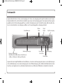
Introduction
Congratulations on your purchase of this Solid State Logic Sigma δelta unit. Please be assured that it will provide you
with many years of reliable service while delivering the pristine quality you expect from any Solid State Logic product.
Sigma δelta is a stylishly designed U rack-mountable unit, providing a remote-controlled analogue summing engine
made possible by Ctrl SuperAnalogue technology. Sigma δelta works by grabbing the automation streams from your
DAW (over a standard Ethernet cable) and using them to drive the analogue signal levels.
The unit front panel offers LED signal level and routing indications, customisable user buttons and a level control. It
also offers a sturdy power switch, headphone socket and an iJack input to easily connect an MP player.
IMPORTANT
Please go to the Sigma page on the Solid State Logic website to register your unit, download the necessary
software and download a copy of the full Sigma User Guide which will guide you through the setup process.
The Solid State Logic home page is at:
www.solidstatelogic.com
From the Sigma page of our website you will also find links to the Frequently Asked Questions (FAQ) area for
any questions you might have or to contact our Technical Support staff.
Sigma Delta Install 1b_Print Layout 05/04/2016 10:39 Page 1

Safety and Installation Considerations
This page contains definitions, warnings, and practical information to ensure a safe working environment.
Please take time to read this page before installing or using this unit. Please do not dispose of these instructions.
General Safety
• Read these instructions.
• Keep these instructions.
• Heed all warnings.
• Follow all instructions.
• Do not use this apparatus near water.
• Do not expose this apparatus to rain or moisture.
• Clean only with dry cloth.
• Do not block any ventilation openings. Install in accordance with the
manufacturer’s instructions.
• Do not install near any heat sources such as radiators, heat registers, stoves
or other apparatus (including amplifiers) that produce heat.
• There are no user-adjustments, or user-servicable items, inside this apparatus.
Do not remove the covers of this apparatus; doing so will invalidate your
warranty.
• Adjustments or alterations to this apparatus may affect the performance such
that safety and/or international compliance standards may no longer be met.
Installation Notes
• When installing this apparatus, either fix it into a standard " rack or place
the apparatus on a secure level surface.
• When this apparatus is rack mounted, fit all rack screws. Rack shelves are
recommended for this apparatus.
• Allow a U gap above and below this apparatus for cooling.
• Ensure that no strain is placed on the cables connecting to this apparatus.
Ensure also that such cables are not placed where they can be stepped on,
pulled or tripped over.
Power Safety
• This apparatus is supplied with a universal power supply, approved and
certified for operation with this apparatus. There are no user-replaceable fuses.
• Use only the Solid State Logic provided power supply. Use of any other power
supply is not covered by your warranty and may cause fire or explosion.
• Any external power supply may become hot during normal operation of the unit.
Use care when handling the power supply.
• Do not attempt to modify the power supply unit in any way.
• Multiple power cords may be supplied with this unit – use only the power cord
appropriate to your local power wiring. Alternative power cords may be used if
rated .A or above and fitted with a -pin IEC connector.
• An external over-current protection device is required to protect the wiring to
this apparatus. This protection device must be installed according to current
wiring regulations. In certain countries this function is supplied by use of a
fused plug.
• If an extension power cable or adaptor is used, ensure that the total power
rating of the power cable and/or adaptor is not exceeded.
• An external disconnect device is required for this apparatus. The appliance
coupler is a suitable disconnect device. The appliance coupler shall remain
readily operable.
• The power socket used for this apparatus should be located nearby and be
easily accessible.
• Unplug this apparatus during an electrical storm or when unused for long
periods of time.
• All power cords must be disconnected to isolate this apparatus completely.
Caution
• Do not operate this apparatus with the covers removed.
• To reduce the risk of electric shock, do not perform any servicing other than
that contained in these Installation Instructions unless you are qualified to do
so. Refer all servicing to qualified service personnel and ensure that all power
cords are disconnected when servicing this apparatus.
Sigma Delta Install 1b_Print Layout 05/04/2016 10:39 Page 2

EN
DE
ES
FR
IT
JP
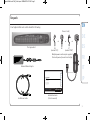
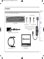
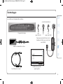
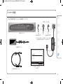
Un-pack
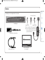
Your Sigma δelta box should contain the following:
5A
Sigma δelta
Installation Guide
Installations-Handbuch
Guia de Instalación
Guide d’Installation
Guida di Installazione
Sigma δelta. This is SSL.
EN
DE
ES
FR
IT
JP
m Ethernet cable
External Mains Adaptor
JP
(marked ‘PSE’)
oror
The Sigma Unit
Multiple power cords may be supplied.
Please dispose of unused cords safely.
or
US
(marked ‘UL’)
EU
Installation Guide
(this document)
Power Cord(s)
Sigma Delta Install 1b_Print Layout 05/04/2016 10:39 Page 3

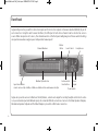
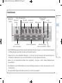
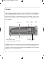
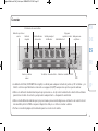
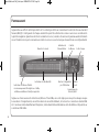
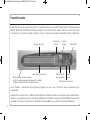
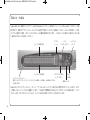
Front Panel
Sigma δelta provides you with stereo line inputs and stereo line outputs on Tascam standard (AES) -pin D-
sub connectors. Using the web browser interface, the left input of each stereo channel can be selected as a mono
source. When an input is set to mono, the channel number on the front panel will glow green. Please note that setting
an input to mono does not give you 2 independent mono inputs!
Sigma also provides access to Mix Insert Send/Returns, a Line Level output for sending headphone feeds into a live
room, an external input and talkback input, all on standard DB- connections. Access to the Main Speaker Outputs,
Alternative Speaker Outputs and the Mix A Output is provided on XLR male connectors.
Power Switch
Customisable
User Buttons
Level Control
Master
Meter
iJack
Input
Headphones
Channel Numbers
Mix Bus A/B Indicators
Input Level Meters
Levels can be set for +18dBu, +22dBu or +24dBu via the web browser interface
Sigma Delta Install 1b_Print Layout 05/04/2016 10:39 Page 4

EN
DE
ES
FR
IT
JP
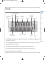
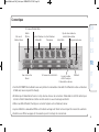
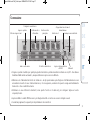
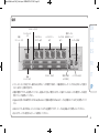
Connections
• The FOOTSWITCH input is suitable for any standard on/off foot switch – by default this turns Talkback On/Off
although this can be changed.
• Use only the provided power supply – the clip above the power inlet should be used to retain the power lead and
so prevent accidental removal or damage.
• Use a standard Ethernet cable (as supplied) to connect Sigma to your computer/network router.
• The USB socket and PROG switch are for SSL diagnostic use and should not be connected or used.
• Please refer to page onward for connector pinouts.
Alternate
Monitor Output
Main Monitor
Output Mix A Output
Footswitch
Input
Clip to secure
power cable
Factory use only
Power Inlet
+V DC
Miscellaneous
Sends and Outputs
Miscellaneous
Returns and Inputs
Stereo Channel Outputs
Stereo Channel Inputs
Ethernet
Sigma Delta Install 1b_Print Layout 05/04/2016 10:39 Page 5

FCC Notice
This equipment has been tested and found to comply with the limits for a Class A digital device, pursuant to part of the FCC Rules. These limits are designed to
provide reasonable protection against harmful interference when the equipment is used in a commercial environment. This equipment generates, uses, and can radiate
radio frequency energy and, if not installed and used in accordance with the instruction manual, may cause harmful interference to radio communications. Operation
of this equipment in a residential area is likely to cause harmful interference in which case the user will be required to correct the interference at his own expense.
Instructions for Disposal of WEEE by Users in the European Union
The symbol shown here is on the product or on its packaging, which indicates that this product must not be disposed of with other waste. Instead, it is the
user’s responsibility to dispose of their waste equipment by handing it over to a designated collection point for recycling of waste electrical and electronic
equipment. The separate collection and recycling of your waste equipment at the time of disposal will help to conserve natural resources and ensure that
it is recycled in a manner that protects human health and the environment. For more information about where you can drop off your waste equipment for
recycling, please contact your local city office, your household waste disposal service or where you purchased the product.
Standards Conformance
This apparatus fully conforms with the current protection requirements of the European community council directives on EMC and LVD.
Limited Warranty
Warranty claims will only be accepted if the purchased product has been used for its intended purpose. Any purchased product used for an
unintended purpose will not be eligible for warranty protection. For all warranty inquiries or claims please address your claim to the dealer that you
purchased the product from – or to Solid State Logic if the purchase was directly from Solid State Logic – within a period of two months from the
date on which you detected its lack of conformity with the terms of the warranty. Please include your original proof of purchase when initiating the claim.
• Within the EU: Pursuant to the Solid State Logic Terms and Conditions under European consumer law the purchaser has full statutory warranty rights for two
years from the date of delivery of the product. The warranty is valid only in those Member States of the European Union (EU) who have adopted
the applicable EU law into their national legislation. The applicable national legislation governing the sale of consumer goods is not affected
by this warranty.
• Outside of the EU: Outside of the European Union a month warranty from date of purchase is applicable.
Out of Warranty Repairs
In the event of a fault arising after the warranty period has expired the unit should be returned to Solid State Logic either directly or via your local dealer. You will be
charged for the time spent on the repair (at Solid State Logic's current repair rate) plus the cost of parts and shipping. Note that no units can be accepted for repair
without prior arrangement (see below).
All Returns
• No unit will be accepted for repair by Solid State Logic unless accompanied by a valid RMA (Return Material Authorisation) number, obtainable from Solid State Logic
prior to shipping.
• All units should be shipped to Solid State Logic in suitable rigid packaging – Solid State Logic cannot be held responsible for any damage caused by shipping units
in other packaging. In such cases Solid State Logic will return the unit in a suitable box, which you will be charged for.
• Do not include the power cable, manual or any other items – Solid State Logic can not guarantee to return them to you.
Sigma Delta Install 1b_Print Layout 05/04/2016 10:39 Page 6

EN
DE
ES
FR
IT
JP
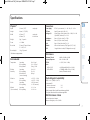
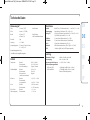
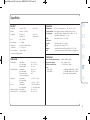
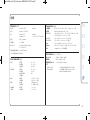
Specifications
Physical *
Depth mm / ." casing only
Height mm / ." ( RU)
Width mm / " casing only
mm / " inc’ rack ears
Weight kg / pounds
Power < Watts
Boxed size mm x mm x mm
" x ." x "
Boxed weight kg / pounds
* All values are approximate
Environmental
Temperature Operating: + to deg. C
Non-operating: – to deg. C
Max. gradient: deg. C/hour
Relative Operating: to %
Humidity Non-operating: to %
Max. wet bulb: deg. C
(non-condensing)
Vibration Operating: < . G ( – Hz)
Non-operating: < . G ( – Hz)
Shock Operating: < G (ms max.)
Non-operating: < G (ms max.)
Altitude Operating: to m
(above sea level) Non-operating: to m
Connections
Power Supply IEC -pin connector, – Vac, – Hz
DC Power mm DC power jack, +V, < A
Analogue I/O -pin D-type socket, balanced, Zin > kΩ, Zo ≈ Ω
-pin XLR-M, balanced, Zo ≈ Ω
Headphones Stereo /" jack socket, Zo ≈ Ω
Footswitch Stereo /" jack socket ( circuit)
iJack Stereo .mm jack socket, Zi ≈ k
Network Pc modular connector; ‘RJ-’ type (bT, Cat)
USB x type-B chassis socket (SSL diagnostic use only)
Performance
Maximum I/O Level +dBu, +dBu or dBu
Frequency Response Hz – kHz ±.dB
THD + N < .% (Hz – kHz)
Noise
CHIP to CHOP < –dBu @ +dBu (Hz – kHz)
CHIP to MIX A < –dBu @ +dBu (Hz – kHz)
(stereo, all channels routed)
Electro Magnetic Compatibility
EN-:, EN-:
Environment E
Initial in-rush current A
sec in-rush current A
Braid-screened cables should be used where applicable
Star Quad cables should be used where applicable
EMC Performance Criteria
Line level inputs and outputs
Measure at mid-gain, noise <–dBu
Sigma Delta Install 1b_Print Layout 05/04/2016 10:39 Page 7

Sigma Delta Install 1b_Print Layout 05/04/2016 10:39 Page 8

EN
DE
ES
FR
IT
JP
Einleitung
Wir gratulieren Ihnen zum Kauf des Solid State Logic Sigma δelta! Das Gerät wird Ihnen viele Jahre lang seinen Dienst
erweisen. Die Verarbeitungs- und Audioqualität sind überragend, genau wie Sie es bei einem Produkt von Solid State
Logic erwarten.
Sigma δelta ist im ansprechenden HE-Rackgehäuse untergebracht und bietet eine fernsteuerbare analoge Summing-
Engine, die über Ctrl-SuperAnalogue-Technologie ermöglicht wird. Sigma arbeitet, indem es die Automationsdaten
aus Ihrer DAW abgreift (über Standard-Ethernet-Kabel) und diese für die Steuerung der analogen Signalpegel einsetzt.
Das Gerät bietet auf der Vorderseite LED-Anzeigen für Signalpegel und Routing, frei belegbare User-Tasten und einen
Pegel-Regler. Ferner einen robusten Netzschalter, eine Kopfhörerbuchse und einen iJack-Eingang zum einfachen
Anschluss von MP-Playern.
WICHTIG
Bitte gehen Sie auf die Sigma-Webseite der Homepage von Solid State Logic, um Ihr Gerät dort zu registrieren,
die notwendige Software herunterzuladen, sowie die vollständige Anleitung (Sigma User Guide), die Ihnen
beim Einrichten hilft.
Die Solid State Logic Homepage finden Sie unter:
www.solidstatelogic.com
Auf der Sigma-Seite der SSL-Homepage finden Sie auch einen Link zum FAQ-Bereich, der Ihre Fragen
beantwortet und über den Sie unser technisches Support-Team kontaktieren können.
Sigma Delta Install 1b_Print Layout 05/04/2016 10:39 Page 9

Sicherheits- und Installationsanweisungen
Dieses Kapitel enthält Bestimmungen, Vorsichtsmassnahmen und praktische Informationen, um ein sicheres Arbeitsumfeld zu garantieren.
Bitte nehmen Sie sich die Zeit, dieses Kapitel zu lesen, bevor Sie das Gerät installieren und benutzen. Bitte bewahren Sie diese Anweisungen auf.
Allgemeine Sicherheit
• Lesen Sie diese Anweisungen.
• Behalten Sie diese Anweisungen auf.
• Beachten Sie die Warnungen.
• Folgen Sie sämtlichen Anweisungen.
• Benutzen Sie das Gerät nicht in der Nähe von Wasser.
• Setzen Sie das Gerät keiner Feuchtigkeit oder Regen aus.
• Nur mit trockenem Tuch reinigen.
• Lüftungsöffnungen nicht blockieren. Nur nach Herstellerangabe installieren.
• Nicht in der Nähe von Hitzequellen einbauen, wie Heizungen, Wärmespeichern,
Öfen oder anderen Geräten (inkl. Verstärkern), die Hitze erzeugen.
• Es gibt keinerlei Einstellungen oder vom Anwender zu wartende Teile im
Inneren des Gerätes. Die Abdeckungen dürfen nicht entfernt werden. Durch
das Entfernen selbiger wird die Garantie ungültig.
• Einstellungen oder Änderungen am Gerät können die Leistung derart
beeinflussen, dass die Sicherheit und/oder die Konformität mit internationalen
Standards nicht mehr erreicht wird.
Hinweise zur Installation
• Bauen Sie das Gerät bei der Installation in ein "-Standardrack ein oder stellen
es auf eine sichere ebene Fläche.
• Bei Rack-Einbau des Geräts, befestigen Sie bitte alle Rack-Schrauben. Der
Betrieb im Rack wird empfohlen.
• Lassen Sie über und unter dem Gerät HE zur Belüftung frei.
• Sorgen Sie dafür, das kein Zug auf den Anschlusskabeln liegt. Achten Sie
ebenfalls darauf, dass die Kabel so liegen, dass niemand darüber stolpern,
darauf treten oder daran ziehen kann.
Sicherheit der Stromzufuhr
• Dieses Gerät wird mit einem Universal-Netzteil ausgeliefert, das für den Betrieb
mit dem Gerät geprüft und zertifiziert ist. Es gibt keine durch den Nutzer
auszuwechselnden Sicherungen.
• Bitte verwenden Sie nur das Original-Netzteil von Solid State Logic. Die Nutzung
anderer Netzteile wird nicht durch die Garantie abgedeckt und kann zu Feuer
oder Explosionen führen.
• Jedes externe Netzteil kann sich während des normalen Betrieb erwärmen.
Seien Sie vorsichtig beim Anfassen des Netzteiles.
• Versuchen Sie nicht, das Netzteil in irgendeiner Weise zu verändern.
• Es können mehrere Netzkabel mit diesem Gerät geliefert werden – nur das
Kabel nutzen, welches für ihr örtliches Netz geeignet ist. Andere Netzkabel
können eingesetzt werden, wenn sie für ,A ausgelegt sind und über einen
dreipoligen IEC Steckverbinder verfügen.
• Die externe Überspannungssicherung ist erforderlich, um den Netzanschluss
des Geräts zu schützen. Sie muss nach geltenden Bestimmungen installiert
sein. In manchen Ländern erfüllt ein Stecker mit Sicherung diese Funktion.
• Wird eine Stromverlängerung oder ein Adapter benutzt, achten Sie darauf, dass
die zulässige Gesamtlast des Stromkabels oder Adapters nicht überschritten
wird.
• Für dieses Gerät ist eine externe Abschaltvorrichtung erforderlich. IEC-
Netzbuchse/-stecker sind eine geeignete Abschaltvorrichtung, deren
Funktionsbereitschaft stets gewährleistet sein muss.
• Die Steckdose für dieses Gerät sollte in der Nähe und leicht zugänglich sein.
• Während Unwettern oder längerer Nichtbenutzung, den Stecker herausziehen.
• Alle Stromkabel müssen abgezogen werden, um das Gerät vollständig vom
Stromnetz zu trennen.
Vorsicht
• Betreiben Sie das Gerät nicht mit geöffneter Gehäuseabdeckung.
• Um die Gefahr von Stromschlägen zu vermeiden, führen Sie bitte keine, bis auf
die im Installations-Handbuch genannten Service-Arbeiten durch, es sei denn,
dass Sie hierfür qualifiziert sind. Überlassen Sie die Instandhaltung
ausschließlich qualifiziertem Service-Personal und stellen sicher, dass bei
Service-Arbeiten alle Netzkabel gezogen sind.
Sigma Delta Install 1b_Print Layout 05/04/2016 10:39 Page 10

EN
DE
ES
FR
IT
JP
Auspacken
Folgendes sollten Sie in der Verpackung finden:
5A
5A
Sigma δelta
Installation Guide
Installations-Handbuch
Guia de Instalación
Guide d’Installation
Guida di Installazione
Sigma δelta. This is SSL.
EN
DE
ES
FR
IT
JP
JP
(bez. als PSE)
oderoder
Eventuell werden mehrere Netzkabel mitgeliefert.
Bitte entsorgen Sie unbenutzte Kabel ordnungsgemäß.
oder
US
(bez. als UL)
EU
Netzkabel
Das Sigma Gerät
m Ethernet-Kabel
Externes Netzteil
Installations-Handbuch
(dieses Handbuch)
Sigma Delta Install 1b_Print Layout 05/04/2016 10:39 Page 11

Vorderansicht
Sigma δelta liefert Ihnen Stereo-Line Eingänge und Stereo-Line-Ausgänge auf -pin D-Sub-Buchsen im Tascam-
Standard (AES). Über die Oberfläche des Webbrowsers kann der linke Eingang jedes Stereokanals als Mono-Quelle
gewählt werden. Steht ein Eingang auf Mono, leuchtet die Kanalnummer auf der Gerätefront grün. Bitte beachten Sie,
dass Sie beim Einstellen eines Eingangs auf Mono nicht unabhängige Mono-Eingänge erhalten!
Sigma bietet auch Zugriff auf Mix-Insert-Send/Returns, einen Line-Level-Ausgang zum Speisen von Kopfhörerwegen
in den Aufnahmeraum, einen externen Eingang und einen Talkback-Eingang, alle auf Standard-DB--Buchsen. Zum
Anschluss von Hauptmonitoren, alternativen Zweitmonitoren und Mix A sind XLR-Buchsen (männlich) vorhanden.
Netzschalter
iJack-Eingang
Kopfhörerausgang
Frei belegbare
User-Tasten
Pegel-
Regler
Master-
Pegel
Kanal-Nummern
Mix-Bus A/B-Anzeige
Eingangs-Pegelanzeige
Pegel können über Web-Browser-Oberfläche auf
+18dBu, +22dBu oder +24dBu gestellt werden
Sigma Delta Install 1b_Print Layout 05/04/2016 10:39 Page 12

EN
DE
ES
FR
IT
JP
Anschliessen
• Der FOOTSWITCH-Eingang ist für jeden Standard-Fußschalter (Ein/Aus) geeignet – in der Standardeinstellung wird
der Talkback Ein/Aus geschaltet, dies kann jedoch geändert werden.
• Verwenden Sie nur das mitgelieferte Netzgerät – der Clip über dem Stromeingang sollte zum Befestigen des
Stromkabels benutzt werden, um so ein versehentliches Lösen oder Schäden zu vermeiden.
• Nutzen Sie ein Standard-Ethernet-Kabel (wie mitgeliefert), um Sigma an Ihren Rechner/Netwerk-Router
anzuschließen.
• Die USB-Buchse und der PROG-Schalter sind nur für SSL-Diagnosezwecke und sollten nicht angeschlossen oder
benutzt werden.
• Die genaue Pinbelegung der Anschlüsse finden Sie von Seite an aufwärts.
Alternativer
Monitor-Ausgang
Hauptmonitor-
Ausgang Mix-A-Ausgang
Fußschalter
Eingang
Sicherungs-Clip für
Stromkabel
nur für
Werkseinstellungen
Gleichstromeingang
+Vdc aus dem Netzteil
Verschiedene
Sends und Ausgänge
Verschiedene
Returns und
Eingänge
Stereo-Ausgangskanäle
Stereo-Eingangskanäle
Ethernet
Sigma Delta Install 1b_Print Layout 05/04/2016 10:39 Page 13

Europäische Union: Anweisung zur Entsorgung von Elektroschrott durch den Benutzer
Dieses Symbol auf dem Gerät oder der Verpackung zeigt an, dass das Produkt nicht im Hausmüll entsorgt werden darf. Bringen Sie es stattdessen zur
entsprechenden Sammelstelle für das Recycling von elektrischen oder elektronischen Geräten. Die ordnungsgemäße Entsorgung und das Recycling dienen
dem Umweltschutz und verhindern mögliche schädliche Auswirkungen auf Umwelt und Gesundheit. Materialrecycling hilft natürliche Rohstoffe
einzusparen. Für weitere detaillierte Informationen zum Recycling dieses Produkts kontaktieren Sie bitte Ihre örtliche Behörde, Ihr
Abfallentsorgungsunternehmen oder den Händler, bei dem Sie dieses Produkt gekauft haben.
Konformitätserklärung
Dieses Gerät entspricht vollständig den Schutzbestimmungen des EU-Rats bezüglich EMV- und Niederspannungs-Störfestigkeit.
Eingeschränkte Garantie
Garantieansprüche können nur geltend gemacht werden, wenn die gekauften Produkte bestimmungsgemäß eingesetzt wurden. Alle gekauften Produkte, die
zweckentfremdet eingesetzt wurden, fallen nicht unter den Garantieschutz. Bitte richten Sie Ihre Garantieansprüche innerhalb von zwei Monaten nach Auftreten des
Schadens/Mangels an Solid State Logic, wenn Sie das Gerät direkt von Solid State Logic gekauft haben, bzw. an den Händler von dem Sie das Gerät gekauft haben.
Bitte legen Sie Ihrer Sendung bei Inanspruchnahme der Garantie den Original-Kaufbeleg bei.
• Innerhalb der EU: Gemäß den Liefer- und Zahlungsbedingungen von Solid State Logic und den europäischen Bestimmungen für Verbraucherschutz, besitzt der
Käufer zwei Jahre gesetzliche Garantieansprüche ab Lieferdatum des Produkts. Die Garantie gilt nur in Mitgliedsstaaten der Europäischen
Union (EU), die entsprechende EU-Rechtsvorschriften in ihre nationale Gesetzgebung aufgenommen haben. Die geltenden nationalen
Gesetzgebungen für den Absatz von Konsumgütern werden von dieser Garantie nicht berührt.
• Außerhalb der EU: Außerhalb der Europäischen Union gilt eine Garantiefrist von Monaten ab Kaufdatum.
Reparaturen Ausserhalb der Garantie
Bei Auftreten eines Fehlers nach Ablauf der Garantiezeit sollte das Gerät direkt oder über Ihren Händler an Solid State Logic zurückgeschickt werden. Die Berechnung
erfolgt entsprechend der erforderlichen Reparaturdauer (zu den jeweils geltenden Stundensätzen), sowie den erforderlichen Teilen und dem Versand. Bitte beachten
Sie, dass keine Geräte ohne vorherige Vereinbarung repariert werden können (siehe unten).
Alle Rücksendungen
• Geräte können nicht ohne gültige RMA (Return Material Authorization) Nummer repariert werden. Diese Nummer erhalten Sie vor dem Versand von Solid State Logic.
• Alle Geräte müssen in geeigneten und stabilen Verpackungen an Solid State Logic geschickt werden. Solid State Logic kann nicht für Schäden aufgrund ungeeigneter
Verpackungen haftbar gemacht werden. Bei ungeeigneten Verpackungen werden die Geräte von Solid State Logic in geeigneten Verpackungen zurückgeschickt. Die
entstehenden Kosten werden entsprechend weiterberechnet.
• Bitte legen Sie der Sendung keine Netzkabel, Bedienungsanleitungen oder andere Gegenstände bei. Solid State Logic kann keine Garantie für deren Rücksendung
übernehmen.
Sigma Delta Install 1b_Print Layout 05/04/2016 10:39 Page 14

EN
DE
ES
FR
IT
JP
Technische Daten
Abmessungen *
Tiefe mm / ," Nur Gehäuse
Höhe mm / ," (HE)
Breite mm / " Nur Gehäuse,
mm / " inkl. Rackeinbauschienen
Gewicht kg
Leistung < Watt
Verpackungsmass mm x mm x mm
" x ," x "
Verpackungsgewicht kg
* alle Werte sind ungefähre Angaben
Umfeld
Temperatur Betrieb: + bis Grad C
Ruhezustand: – bis Grad C
Max. Schwankung: grad C/stunde
Luftfeuchtigkeit Betrieb: bis %
Ruhezustand: bis %
Max. wet bulb: grad C
(nicht-kondensierend)
Vibration Betrieb: < , G ( – Hz)
Ruhezustand,
ausgeschaltet: < , G ( – Hz)
Stoss Betrieb: < G (ms max.)
Ruhezustand: < G (ms max.)
Höhe (über Betrieb: – m
Meeresspiegel) Ruhezustand: – m
Anschlüsse
Netzteil Netz IEC Pol Steckverbinder – V AC, – Hz
Stromeingang mm Stecker, Gleichstrom (DC) , +V, < A
Analog I/O -pol Sub-D-Stecker, Symmetrisch, Zi > kΩ, Zo ≈ Ω
-pol XLR-M, Symmetrisch, Zo ≈ Ω
Kopfhörer , mm Stereo-Klinkenbuchse, Zo ≈ Ω
Footswitch , mm Stereo-Klinkenbuchse ( Schaltkreis)
iJack ,mm Stereo-Klinkenbuchse, Zi ≈ k
Netzwork Pc Modularer Anschluss; ‘RJ-’ Typ (bT, Cat)
USB x Buchse Typ B (nur für SSL-Diagnosezwecke)
Leistung
Maximaler I/O-Pegel +dBu, +dBu oder dBu
Frequenzgang Hz – kHz ±.dB
Verzerrungen über Frequenz < .% (Hz – kHz)
Geräuschspannungsabstand
CHIP zum CHOP < –dBu @ +dBu (Hz – kHz)
CHIP zum MIX A < –dBu @ +dBu (Hz – kHz)
(Stereo, alle Kanäle geroutet)
Sigma Delta Install 1b_Print Layout 05/04/2016 10:39 Page 15

Sigma Delta Install 1b_Print Layout 05/04/2016 10:39 Page 16

EN
DE
ES
FR
IT
JP
Introducción
Le felicitamos por la compra de esta unidad Solid State Logic Sigma δelta. Le aseguramos que ésta le proporcionará
muchos años de servicio fiable presentando al mismo tiempo la excelente calidad que puede esperar de cualquier
producto de Solid State Logic.
Sigma δelta es una unidad de estantes apilables U diseñada con estilo, que incluye un mezclador de software
analógico por control remoto gracias a la tecnología Ctrl SuperAnalogue. Sigma funciona captando los streams de
automatización desde la estación de trabajo de audio digital o DAW en sus siglas inglesas (a través de un cable
Ethernet estándar) y utilizándolos para conducir los niveles de señal analógica.
El panel frontal de la unidad muestra el nivel de la señal LED y las indicaciones de enrutamiento, botones de usuario
personalizables y un control de nivel. También incluye un robusto interruptor, enchufe para auriculares y una entrada
iJack para conectar fácilmente con un MP.
IMPORTANTE
Consulte la página dedicada a Sigma en la página web de Solid State Logic para registrar la unidad y bajar el
software necesario así como una copia de la Guía Completa del Usuario de Sigma que le servirá de guía
durante la instalación
Página web de Solid State Logic es: www.solidstatelogic.com
En la página dedicada a Sigma de nuestra web también encontrará enlaces que le llevarán a las Preguntas
Frecuentes para cualquier duda que pueda tener o para ponerse en contacto con nuestro personal de soporte.
Sigma Delta Install 1b_Print Layout 05/04/2016 10:39 Page 17
La pagina sta caricando ...
La pagina sta caricando ...
La pagina sta caricando ...
La pagina sta caricando ...
La pagina sta caricando ...
La pagina sta caricando ...
La pagina sta caricando ...
La pagina sta caricando ...
La pagina sta caricando ...
La pagina sta caricando ...
La pagina sta caricando ...
La pagina sta caricando ...
La pagina sta caricando ...
La pagina sta caricando ...
La pagina sta caricando ...
La pagina sta caricando ...
La pagina sta caricando ...
La pagina sta caricando ...
La pagina sta caricando ...
La pagina sta caricando ...
La pagina sta caricando ...
La pagina sta caricando ...
La pagina sta caricando ...
La pagina sta caricando ...
La pagina sta caricando ...
La pagina sta caricando ...
La pagina sta caricando ...
La pagina sta caricando ...
La pagina sta caricando ...
La pagina sta caricando ...
La pagina sta caricando ...
La pagina sta caricando ...
La pagina sta caricando ...
La pagina sta caricando ...
La pagina sta caricando ...
-
 1
1
-
 2
2
-
 3
3
-
 4
4
-
 5
5
-
 6
6
-
 7
7
-
 8
8
-
 9
9
-
 10
10
-
 11
11
-
 12
12
-
 13
13
-
 14
14
-
 15
15
-
 16
16
-
 17
17
-
 18
18
-
 19
19
-
 20
20
-
 21
21
-
 22
22
-
 23
23
-
 24
24
-
 25
25
-
 26
26
-
 27
27
-
 28
28
-
 29
29
-
 30
30
-
 31
31
-
 32
32
-
 33
33
-
 34
34
-
 35
35
-
 36
36
-
 37
37
-
 38
38
-
 39
39
-
 40
40
-
 41
41
-
 42
42
-
 43
43
-
 44
44
-
 45
45
-
 46
46
-
 47
47
-
 48
48
-
 49
49
-
 50
50
-
 51
51
-
 52
52
-
 53
53
-
 54
54
-
 55
55


Solid State Logic Sigma Delta Guida d'installazione
- Tipo
- Guida d'installazione
in altre lingue
Documenti correlati
-
Solid State Logic Sigma Delta Guida d'installazione
-
Solid State Logic XL-Desk Guida d'installazione
-
-
Solid State Logic SSL 2 Manuale del proprietario
-
Solid State Logic SSL 2+ Manuale del proprietario
-
-
Solid State Logic X-Panda Guida d'installazione
-
SSL Alpha Channel Manuale del proprietario
-
SSL Alpha VHD-Pre Guida d'installazione
Altri documenti
-
Montarbo 459S Manuale del proprietario
-
-
Yamaha n12 Manuale del proprietario
-
-
Rotel RCD-06 Manuale utente
-
-
EcoFlow Portable Power Station Grounding Adapter Manuale utente
-