Rockford Fosgate T152-S Installation & Operation Manual
- Categoria
- Altoparlanti
- Tipo
- Installation & Operation Manual

Ill
I I
WE
COMPONENT
SPEAKERS
T152-S
•
T16-S
T165-S
•
T1675-S
T1T-S
Serial
Number:
_____
_
Date
of
Purchase:
_____
_
Installation
&
Operation

2
Introduction
Dear
Customer,
Congratulations
on
your
purchase
of
the
world's
finest
brand
of
car
audio
amplifiers.
At
Rockford
Fosgate
we
are
fanatics
about
musical
reproduc-
tion
at
its
best,
and
we
are
pleased
you
chose
our
product.
Through
years
of
engineering
expertise,
hand
craftsmanship
and
critical
testing
procedures,
we
have
created
a
wide
range
of
products
that
reproduce
music
with
all
the
clarity
and
richness
you
deserve.
For
maximum
performance
we
recommend
you
have
your
new
Rockford
Fosgate
product
installed
by
an
Authorized
Rockford
Fosgate
Dealer,
as
we
provide
specialized
training
through
Rockford
Technical
Training
Institute
(RTTI).
Please
read
your
warranty
and
retain
your
receipt
and
original
carton
for
possible
future
use.
Great
product
and
competent
installations
are
only
a
piece
of
the
puzzle
when
it
comes
to
your
system.
Make
sure
that
your
installer
is
using
100%
authentic
installation
accessories
from
Rockford
Fosgate
in
your
installation
.
Rockford
Fosgate
has
everything
from
RCA
cables
and
speaker
wire
to
power
wire
and
battery
connectors.
Insist
on
it!
After
all,
your
new
system
deserves
nothing
but
the
best.
To
add
the
finishing
touch
to
your
new
Rockford
Fosgate
image
order
your
Rockford
accessories,
which
include
everything
from
T-shirts
to
jackets.
Visit
our
web
site
for
the
latest
information
on
all
Rockford
products;
www.
rockfordfosgate.
com
or,
in
the
U.S.
call1-800-669-9899
or
FAX
1-800-398-3985
.
For
all
other
countries,
call
+001-480-967
-3565
or
FAX
+001-480-966-3983.
Table
of
Content
2
Introduction
3-5
Specifications
6-11
Installation
Installation
Considerations
Mounting
Wiring
Tweeter
Axis/Attenuation
Switch
10-11
Additional
Languages
French
Spanish
German
Italian
12
Limited
Warranty
Information
If
,
after
reading
your
manual
,
you
still
have
questions
regarding
this
prod
-
uct
,
we
recommend
that
you
see
your
Rockford
Fosgate
dealer
.
If
you
need
further
assistance
,
you
can
call
us
direct
at
1-800-669-9899.
Be
sure
to
have
your
serial
number
,
model
number
and
date
of
purchase
available
when
you
call.
Safety
This
symbol
with
"WARNING
"
is
intended
to
alert
the
user
to
the
presence
of
important
1'
WARNING
instructions.
Failure
to
heed
the
i
nstructions
~
will
result
in
severe
injury
or
death
.
This
symbol
with
"
CAUTION
"
is
intended
to
alert
the
user
to
the
presence
of
important
1'
CAUTION
instructions
.
Failure
to
heed
the
instructions
~
can
result
in
injury
or
unit
damage.
•
To
prevent
injury
and
damage
to
the
unit
,
please
read
and
follow
the
instructions
in
this
manual.
We
want
you
to
enjoy
this
system
,
not
get
a
headache
.
•
If
you
feel
unsure
about
installing
this
system
yourself,
have
it
installed
by
a
qualified
Rockford
Fosgate
technician
.
•
Before
installation
,
disconnect
the
battery
negative
(-)
terminal
to
prevent
damage
to
the
unit
,
fire
and/or
possible
injury
.
©?012
Rockford
Corporation
All
Rights
Reversed
ROCKFORD
FOSGATE
and
associated
logos
where
appl
cab
e
are
reg1ster~d
tr1demdrk,
of
Rockford
Corporation
i1
the
United
States
and/or
other
countries
All
other
trademarks
are
the
property
of
their
respective
owners.
Specifications
subject
1
0
cha:1qe
w·trliill'
n11tice
F
Jr
use
1n
veh
c
les
Ol'ly

~
·"'
·
~
·
..
,.,
Mod
el
o
~
I
j
t"I'.I
·
1BI
'""._
...
N
om
i
na
l Dia
mete
r
Desc
ripti
on
Nom
ina
l
Im
p
edanc
e
Fre
quency
Re
spons
e
Voice
Coil
Di
ame
t
er
P
ow
er
Ra
ti
ng
(R
ivi
S/
P
eak)
Fs-
Fr
ee A
ir
R
eso
nanc
e
Ot
s
Vas
Sensi
ti
v
ity
(1W/
1
ivl)
Sensit
i
vity
(2
.83V/1M)
X
max
Mounting
D
iameter
Mounti
ng
Depth
Gnlle/Trim
Ring
Adap
to
r
P
late
Specifications
T152-S
T16-S
T165-S
T1675-S
T1T-S
5.25"
6"
6.5"
6.75"
1.0"
(133mm)
(153mm)
(165mm)
(171
.
5m
m)
(25mm)
2-Way
2-Way
2-Way
2-Way
Tweeter
4Q
4Q
4Q
4Q
4Q
65-22kHz
60-22kHz
60-22kHz
55-22kH
z
3kHz-22kHz
1.
1"
11"
11"
1.2"
1.
0"
(27
.
9mm)
(27.9mm)
(27.9mm)
(30.5m
m)
(25.4mm)
75W
I
150W
BOW
I
160W
BOW
1160W
100W
I
200W
75W
1150W
65Hz
67Hz
67Hz
56
Hz
1.B
kHz
0.60
O.B O.B
0.
59
N/A
0.
341P
0.3
5
IP
0.
351
P
0.56
IP
NIA
(9.6L)
(9.BL)
(9
.
BL)
(15
.
9L)
B7dB B6dB
B6dB
B9dB
90dB
90dB
B9dB
B9dB
92
dB
93dB
0.
16
"
0.1
6"
0.16
"
0.
15
"
NIA
(4
.
0mm)
(4
.
2mm)
(4.
2
mm)
(3.7mm)
4.
B1
" 5.
05
" 5.
05
" 5.
6B
"
1.75"
(1
2
2.2mm)
(128
.
2mm)
(128
.
2mm)
(144
.
2mm)
(45mm)
1.
99
" 1.9
3"
1.93" 2
.51
" 0.91"
(
50
.
5m
m) (4
9.0mm)
(4
9.0mm)
(64.0mm
) (
23
mm)
YES Y
ES
YES
Y
ES
YES
YES
YES
Y
ES
YES
NO
See
pages
4-5
for
additi
o
nal
dim
en
sions
CEA
203
1
Po
w
er
h
andli
ng
on
Rockfo
rd
Fosga
te sp
ea
k
ers
con
f
or
m
to
CEA
-20
31
i
ndus
tr
y
sta
n
da
r
ds
.
Th
is
m
eans
yo
ur
speaker
has
the
c
apa
c
ity
to
handle
po
w
er
un
der
cont
inuous d
ema
n
d,
not
inst
anta
n
eous
power
h
an
dl
ing
that
over
time
ca
n
damag
e
vo
i
ce
coils
.
3

4
Specifications
T152-8
6.02"
(153.0mm)
T16-S/T165-S
6.14"
~-__
___
(156.0mm)
6.69"
(170.0mm)
Diameter
T1675-S
5.43"
(138.0mm)
l=-o
Diameter
"\\'i
_l\1
'
~
~l
6.10"
(155.0mm)
Diameter
5.59"
(142.0mm)
Diameter
6.22"
~q
1.06"
(158.0mm)
(27.0mm)
'];'
l
t
II/(
rll
1 2.45'
1.99" (
62
]
rL;::Z.;;
I I
J
(50.1mm)
.......
mm)
4.81",
~
122.2mm)
I
=~
6.89"
(175.0mm)
"*"
5.05"
(128.2mm)
?~I
1.
18
"
(29.9mm)
I
6.18"
(157.0mm)
Diameter
6.97"
~
(m.ommJ
1.18"
(29.9mm)
5.68"
(144.2mm)
~
2.94"
I (74.7mm)
2.51"
1
(64.0mm) I
l I

T1T-S
Surtace
Mount
Flush
Mount
0.30"
(Bmm)
r-
2.13"
11
~---
0.32"
9
~
~Omm)
Tweeter
Crossover
Component Crossover
4.57"
(116mm)
--
_
1.75"
(44mm)
4
.5
7"
(116mm)
I
"2
~
(23mm)
r
0.
91"
LS
U
LJU
~
~
3.16"
(BOmm)
~
r<is~~>
--j
--r
1.18"
~m)
~
]
0.97"
~
(25mm)
I
1.26"
I
!--
(32mm)
~
Specifications
il
lus
.-1.2
5

6
Installation
Contents
•
(1)
Pair
Power
Series
Full
Range
Component
Speakers
•
(1)
Pair
of
grilles/trim
rings
•
Mounting
Hardware
•
(1)
Set
adapter
plates
(5"x7"/6"x9")
Installation
Considerations
Before
beginning
any
installation,
follow
these
simple
rules:
1.
Be
sure
to
carefully
read
and
understand
the
instructions
before
attempting
to
install
these
speakers
.
2.
For
safety,
disconnect
the
negative
lead
from
the
battery
prior
to
beginning
the
installation.
3.
For
easier
assembly,
we
suggest
you
run
all
wires
prior
to
mounting
your
speakers
in
place.
4.
Use
high
quality
connectors
for
a
reliable
installation
and
to
minimize
signal
or
power
loss
.
5.
Think
before
you
drill!
Be
careful
not
to
cut
or
drill
into
gas
tanks,
fuel
lines,
brake
or
hydraulic
lines,
vacuum
lines
or
electrical
wiring
when
working
on
any
vehicle.
If
installation
in
a
boat,
take
care
not
to
cut
or
drill
through
the
main
hull.
6.
Never
run
wires
underneath
the
vehicle.
Running
the
wires
inside
the
vehicle
or
hull
area
provides
the
best
protection.
7.
Avoid
running
wires
over
or
through
sharp
edges.
Use
rubber
or
plastic
grommets
to
protect
any
wires
routed
through
metal,
especially
the
firewall.
Mounting
Mid-Bass
1.
Determine
where
the
speakers
will
be
mounted.
Ensure
an
area
l
arge
enough
for
the
speaker
to
mount
evenly.
Be
sure
that
the
mounting
location
is
deep
enough
for
the
speaker
to
fit;
if
mounting
in
a
door,
operate
all
functions
(windows,
locks
,
etc
.)
through
their
entire
operating
range
to
ensure
there
is
no
obstruction.
2.
Refer
to
the
specification
chart
to
determine
the
proper
diameter
hole
to
cut
for
your
speaker
model.
Cutting
and
mounting
templates
can
be
found
at
www.rockfordfosgate.com.
3.
Mark
the
locations
for
the
mounting
screws.
Drill
the
holes
with
a
1/8"
bit.
4.
Feed
the
speaker
wires
through
the
cutout
and
connect
to
the
speaker
terminals
.
Be
sure
to
observe
proper
polarity
when
connecting
the
wires.The
speaker's
positive
terminal
is
indicated
with
a"+
".
5.
Fit
the
trim
ring
over
the
speaker
and
mount
into
place
using
four
(4)
screws
.
6.
Tighten
the
screws
until
the
speaker
is
snug
in
place
to
prevent
rattling.
Do
not
over
tighten
the
screws.
Mounting
tab
removal
for
some
installations
0
Use
pliers
to
break
off
plastic
tab.
i
ll
us
.-
2.
1
\ \ l .
JA,
A B
reakoff
V
mounting
ta
b.
Example
of
standard
door
installation
.··i~
·
..
~
·
··
...
to
Align
Hol
es
..
,...
...
············
··
··
··
i'lu
s.
-
2.2
Tweeter-
Discreet
Dual
Clamp
(DOC™)
1.
Determine
where
the
speake
rs
will
be
mounted
.
Ensure
an
area
large
enough
for
the
speaker
to
mount
evenly.
Be
sure
that
the
mounting
location
is
deep
enough
for
the
speaker
to
fit;
if
mounting
in
a
door,
operate
all
functions
(windows,
locks,
etc
.)
throug
h
their
entire
operating
range
to
ensure
there
is
no
obstruction
.
2.
Mark
the
location
for
the
mounting
hole.
Drill
the
hole
with
a
standard
1.75
inch
(45mm)
hole
saw
.
3.
With
a
single
center
screw
secure
the
inner
cup
from
the
front
of
the
door
panel
to
the
outer
cup
from
back
of
the
doo
r
pa
ne
l.
Tighten
the
screw
until
balanced
pressure
is
applied
to
both
faces
of
the
mounting
surface.
4.
Feed
the
speaker
wires
through
the
cutout
and
connect
to
the
speaker
terminals
.
Be
sure
to
observe
proper
polarity
when
connecting
the
wires.
The
speaker's
lead
wires
are
indicated
with
a
RED
wire
"+"
and
a
BLACK
wire"-".
5.
Simply
snap
the
tweeter
into
place
and
secure
wi
th
a
snap-on
trim
ring
.
Removal
is
easy
if
needed
.
The
protective
gril
le
on
the
tweeter
is
non-removable
and
an
integra
l
part
of
the
design.
illus
.-
2.3
Us
e tip of a
small
flat
screwdri
ver
to
remove
twe
eter
Example
of
tweeter
mounting
using
Discreet
Dual
Clamp
(DDC™l

Wiring
Standard
1.
Use
illustration
for
proper
connection
and
be
sure
to
maintain
speaker
Installation/System Setup
illus.-3.1
polarity.
2.
Use
only
"TWEETER"
input(s).
Example
of
T1
component
standardlbi-amp
wiring
Default
Setting
,,'*' ........ ,
' '
I
81-AMP
~
Bi-amp
1.
Use
illustration
for
proper
connection
and
be
sure
to
maintain
speaker
polarity.
•OFF,
rON'
...........................
~_tEI.f
..
..
,
.....
'
'
Standard
Mode
2.
Remove
4
screws
from
crossover
bottom
to
detatch
cover.
I~/
-
,
-
~
-
,".//·,.-, -/A"'!
3.
When
81-AMP
switched
OFF
for
one
amplifier,
use
only
"TWT"
input.
4.
When
81-AMP
switched
ON
for
two
dedicated
amplifier,
use
both
"TWT"
and
"WFR"
inputs
Remove
4
screws
from
~
bottom
to
detatch
cover
#
T1
T-S
Crossover
1.
Use
illustration
for
proper
connection.
2.
Be
sure
to
maintain
speaker
polarity.
3.
Connecting
the
positive
wire
to
OdB
matches
the
amplitude
of
the
tweeter
to
the
mid-range
(woofer).
4.
Connecting
positive
wire
to
-2dB
or
-4dB
to
reduce
the
amplitude
of
the
tweeter
-2dB
or
-4dB
lower
than
the
mid-range,
(ideal
for
twee
te
rs
located
high
in
door
panels
and
mid
-
range
low
in
the
kick
panel).
Tweeter
On
-
Axis
Tweeter
Off-Axis
diU$
3.2
Example
of
T1T·S
wiring
'
·-----------------------
'
'
'
(TWT)
Fu
'I
-Range
Amp
l1
l1er
Tweeter
ON/OFF
Axis
Switch
Tweeter
(TWT)
Tweeter
(TWT)
1.
Set
to
ON
or
OFF
to
match
position
of
tweeter
relat
i
ve
to
listener.
Default
OFF
position
satisfies
most
installations
.
Tweeter
Attenuation
Switch
1.
OdB
matches
the
amplitude
(no
increase/no
attenuation)
of
the
tweeter
to
the
same
level
as
the
mid-range
(woofer).
2.
+2dB
increases
and
-2
dB
reduces
the
amplitude
of
twe
ete
r
in
relation
to
the
mi
d-range
,
(ideal
when
matching
offset
installation
like
tweeters
located
high
in
door
panels
and
midranges
low
in
kick
panels).
Tweete
r
On-Axis
Tweet
er
Off
-
Ax
is
illus.-4
.1
(
li+~ter
l>is
SwocJil
.....
,...
..
..
~
...
"'
.....................
--
.....
'-
......
-·
'
'Iii':
\~
·2
d /
.
.
Tw
ee
ter
Atte-nuat
ion
Switch
'.
)
j~
:
Example
of
T1
component
tweeter
setup
..........................................
'
7

Installation
8
Adapter
Plate
Template
·
6.75"
Hole
Mounting
Remove
Shaded
Areas
to
Mount
5.
25"
(T152-S)
Remove
Shaded
Areas
to
Mount
6"/6
.5"
(T16-S/T165-S)

Adapter
Plate
Template
·
6"x9"
Hole
Mounting
Mounting
for
5.
25
"
(
T152-S
)
Installation
*
Remove
for
Optional
Tweeter
-
).2
9

10
Fran9ais
Considerations
Concernant
l'installation
Avant
de
commencer
l'installali
on,
suivez
les
regles
ci-dessous:
1.
Veillez
a
bien
lire
et
comprendre
les
instructions
avan
t
d'es
s
ayer
d'installer
les
haut-parleurs.
2.
Par
mesure
de
securite.
debranchez
le
Iii
negatif
de
Ia
bat
t
er
ie
avant
de
commencer
!'installa
tio
n.
3.
Pour
taciliter
le
montage
des
haut-parleurs,
il
est
conseille
d'
installer
taus
les
cables
au
prea
l
able.
4.
Utilisez
des
connecteurs
de
haute
qualite
pour
assurer
une
i
nstallation
liable
et
reduire
au
mi
ni
mum
Ia
perle
de
s
ignal
ou
de
puissance
.
5.
Reflechissez
bien
avant
de
percer.Veillez
a
ne
pas
couper
ou
percer
le
reservoir
d'essence,
le
cablage
electrique
ou
les
conduites
de
carburant,
de
freinage
hydraulique
ou
de
depression
en
travaillant
sur
un
vehicule.
En
cas
d'installation
sur
un
bateau,
veillez
a
ne
pas
couper
au
percer
Ia
coque
principale.
6.
Ne
jamais
faire
passer
de
fils
sous
le
vehicule.
Leur
installation
a
l'interieur
du
vehicule
au
de
Ia
coque
assure
Ia
meilleure
protection.
7.
Evitez
de
faire
passer
des
fi
ls
sur
des
bards
tranchants
au
dans
des
orifices
a
ar@tes
vives
. U
ti
l
isez
de
s ba
gu
es
en
caoutchouc
au
en
pla
s
tique
pour
proteger
les
fils
traver
s
ant
une
plaque
de
m
etal,
notamm
e
nt
le
tablier.Emplacemenls
De
Montage
Montage
(illus.-2.1
-
2.3)
Mid-Bass
1.
Delerminez
!'emplacement
des
haut-parleurs.Veillez
ace
que
Ia
surface
plane
so
it
assez
gran
de
pour
assurer
un
contact
uniforme
du
haut-parleur.Verifiez
que
!'
emplacement
est
assez
profond
po
ur
le
haut-parleur
;
en
cas
de
montage
dans
une
portiere
,
actionnez
toutes
les
commandes
(fe
n
@tres,
serrures.
etc
.)
jusqu
'
aux
extremi
t
es
de
leurs
courses
pour
vous
assurer
qu'il
n'y
a
pas
d'obstr
uct
ion.
2.
Consultez
le
tableau
des
caracteri
s
tique
s
pour
de
terminer
le
diametre
de
I'
orifice
a
de
co
u
per
pour
vo
t
re
mod
e
le
de
haut-parleur.
Le gaba
ril
fourni
do
nne
a
ussi
le
bon
di
am
et
re de
de
c
ou
pe
.Les
gabarit
s de
co
upe
et
de
mo
ntage
sont
di
s
ponibl
es
sur
Ia
pag
e
www.rockfordfosgate.com
/r
fte
ch
.
3.
Marquez
!'
emplacement
des
vis
de
montage.
Percez
les
trous
avec
une
meche
de
1/8
de
p
ouce
(3,2
mm).
4
Faites
passer
les
fils
de
haut-parleur
a
travers
!'orifice
decou
pe
et
branchez-les
aux
barnes
du
h
aut-
parleur.Veillez
a
bien
re
s
pecter
Ia
polarite
Iars
du
branchem
e
nt.
La
borne
positive
du
haut-
par
leur
est
indiquee
par
un" +
..
.
5.
Di
s
po
se
z l'
anneau
de
garniture
sur
le
haut-parleur
et
fixez
-
le
avec
quatre
(4)
vis.
6.
Se
rr
ez l
es
vi
s
ju
s
qu
'a
ce
qu
e
le
haut
-
parleur
soil
bien
ajusle
,
de
fa~
on
a
prevenir
tout
cliqueti
s,
mai
s
e
vitez
tout
serrage
ex
cessif
.
Tweeter-
Discr
ee
t
Dual
Clamp
(DOC"')
1.
Determiner
l'endroit
de
montage
des
enceintes.
S'assurer
que
Ia
zone
est
suffisamment
larg
e p
our
manter
!'enceinte
uniformement.
S'assurer
que
!'emplacemen
t
de
montage
est
suffisamment
p
rof
ond
pour
que
!'enceinte
y
rentre;
si
on
Ia
monte
sur
une
porte
,
activer
toutes
les
fonctions
(fe
n
etres,
verrous,
etc.)
dans
louie
leur
plage
d'exploitation
pour
s'a
ss
urer
qu'il
n'y
a
pas
d'obstructio
n.
2.
Marquer
!'emplacement
du
trou
de
montage.
Percer
le
trou
a
l'aide
d'une
scie
cloche
sta
nd
ar
d
de
45
mm
(1,75
po
).
3.
A
l'
a
id
e d'
un
e
se
ul
e
vis
centrale,
securi
s
er
Ia
coupelle
inte
rn
e
du
devan
t
du
panneau
de
po
r
te
sur
Ia
coup
e
li
e e
xlerne
du
dos
du
panneau
de
porte
. S
errer
Ia
vi
s
jusqu
'a
ce
qu'un
e
pr
ess
ion
e
qu
ili
bree
soil
appliquee
s
ur
le
s
deux
f
aces
de
Ia
s
urfa
ce
de
montage
.
4.
Alimenter
le
s
fil
s d'
en
c
ein
te a
travers
Ia
decoupe
et
c
onn
ec
ter
aux
barn
es
d
'e
n
ce
inte
. S'
ass
ur
er
d'observer
Ia
polarile
appropriee
tors
de
Ia
connexion
des
fils.
Les
fils
de
I'
enceinte
sont
in
di
ques
par
un
Iii
ROUGE
" +
..
et
un
fil
NOIR
" -
..
5.
II
s
uffit
d'
en
c
lencher
le
tw
e
eter
en
pl
a
ce
et
de
securi
se
r a l
'a
ide
d'une
bague
de
ga
rn
itu
re
a
en
c
len
cher. Si
be
so
in.
Ia
de
po
se
es
t
ai
see.
La
grill
e
prot
ec
tri
ce
s
ur
le
tw
ee
ter
es
t
in
a
movibl
e et fa
it
pa
rti
e
int
eg
rate
du
d
es
ign.
Cablage
(illus.-3.1
&
3.2)
Standard
1.
Utili
se
r
!'illu
s
tration
pour
une
bonne
c
onn
e
xion.
2. As
sur
ez
-vous de ma
intenir
orat
e
ur
polarit
e.
Bi-ampere
s
1.
Utiliser
!'
illustration
pour
Ia
c
onnexion
et
assurez-vou
s
de
maintenir
orateur
polarite.
2.
Suppres
s
ion
de
4
vi
s de
liaison
a
bas
detatch
couverture
.
3.
BI
-
AMP
Lor
s
que
l
'a
rret
d'
un
amplificateur,
utilisez
uniquem
en
t
"TWT"
input.
4.
Lors
que
BI-AMP
ten
s
ion
pour
deu
x
dedie
s
amplificateur,
ut
ilis
er
le
s
deux
"
TWT"
et
"WFR"
inp
ut
s.
T1T-
S Ca
bl
a
ge
1.
Vo
ir
le
bran
cheme
nt
correct
sur
!'illu
s
tr
a
tion
.
2.
Ve
ill
ez a
maint
e
nir
Ia
polarite
du
haut
-
parl
e
ur
.
3.
Le
br
ancheme
nt
du
fil
po
s
itif
a
Ia
born
e 0
dB
acc
ord
e
!'
a
mplitud
e
du
tw
ee
ter s
ur
ce
ll
e
du
ha
ut
-
pa
rl
eu
r.
4. Le
bran
c
hem
e
nt
du
Iii
po
s
itif
a
Ia
borne
-2
dB
au
-4
dB
r
ed
uit
!'amplitud
e
du
tw
ee
ter de -2 ou -4
dB
par ra
pport
a
ce
ll
e
du
haut
-
parleur
de
medium
(id
e
al
tor
s
qu
e l
es
tw
ee
t
ers
s
ont
s
itu
es
en
h
au
l d
es
pa
nn
e
au
x de
port
e et
le
s
haut
-
parleurs
de
medium
dans
l
es
pa
nn
ea
ux
de
se
uil)
.
Axis
ON-OFF
1.
Re
gi
e sur
ON
au
OFF
match
ala
p
os
ition
relative
de
tw
ee
ter a
l'audit
e
ur.
Par
det
a
ut
OFF
sa
ti
sf
ait
Ia
plup
a
rt
d
es
in
s
tallation
s.
Switch
dB
1.
O
dB
co
rre
spo
nd
a !'a
mplitude
(
pas
d'a
ugm
e
nt
a
tion
I
sa
ns
att
e
nu
a
ti
o
n)
de
s
le
tweeter
au m
eme
n
iv
e
au
que
le
milieu
de
gamm
e
(wo
ofe
r)
.
2.
+2
dB
augmente
-
2d
B
et
n\duit
!
'a
mplitud
e de
tw
ee
ter
en
ra
ppo
rt
a Ia moye
nn
e g
amme,
(id
ea
l po
ur
ad
apter
!'in
sta
ll
ati
on
off
se
t
co
mm
e l
es
tw
ee
ters s
itu
e en
haut
d
es
panneau
x de
port
e
et
M
id
ranges
Ia
ibie
en
ki
ck
panneau
x)
Espafiol
Consideraciones
para
Ia
instalaci6n
Antes
de
c
om
enzar
cualquier
instalaci6n,
sig
a
est
as
simples
normas:
1.
Asegu
rese
de
leer
cuidadosamente
y de
ente
nder
las
instrucciones
antes de
tr
at
ar
de
instalar
estos
altavo
ce
s.
2.
Por
segu
ridad,
desconecte
el
conduc
t
or
n
egative
de
Ia
bateria
antes
de c
om
en
zar
Ia
instalaciOn
.
3.
Para
fac
il
it
ar
el
montaje,
sugerim
os
que
ti
enda
todos
los
cables
ante
s
de
mon
tar
sus
altavoces
en
su
sitio
.
4.
Ut
ilice
co
ne
ctores
de
alta
calidad
para
tener u
na
instalaci6n
confiable
y
pa
ra
reducir
al
minima
las
perdidas
de
seiial
o
de
palencia.
5.
tPiense
sie
m
pre
antes
de
perlorar!
Teng
a cuida
do
de
no
cortar
ni
perforar
en
t
anq
ues
de
combustible,
tuberia
s de c
ombustible,
frenos
o
hidnl
u
li
ca
s,
tuberias
de
vacio
o
cablead
o elec
trico
al
trabajar
en
un
vehic
ulo.
Si
Ia
instalaci6n
se
hac
e
en
un
bote,
tenga
cuidado
de
no
cort
ar
ni
perforar
a
traves
del
cas
co
pr
incipal.
6.
Nun
ca tienda
cables
abajo
del
vehiculoTe
n
de
r
los
cables
adentro
de
l
veh
i
culo
o
casco
proporciona
Ia
mejor
pro
tecci6n.
7.
E
vile
t
en
der
cables
arriba
o a
traves
de
bo
rdes
filosos.
Use
arandela
s aisl
ant
es
de
caucho
par
a
proteger
los
cables
tendidos
a
traves
de met
al.
especial
mente
Ia
mampa
ra
co
rt
aluegos.Montage
Montaje
(illus.-2
.
1-
2.3)
Mid-Bass
1.
Determi
ne
ad6nde
se
montara
los
alta
voces
.A
segurese
de
que
haya
un
ar
ea
su
fi
cientemente
grande
para
mo
nt
ar
de
manera
plana
el
altav
oz.Asegu
rese
de
que
el
Iugar
de
mo
ntaje
sea
suficientemente
profu
nda p
ara
que
quepa
el
altavoz,
si se
manta
en
una
puerta
, a
cc
i
one
to
das
las
funciones
(ventan
as
,
cerradura,
et
c
.)
en
toda
su ga
ma
de
fun
c
ionamiento
para
asegu
ra
r
se
de
que
no
haya
obs
t
ru
cc
i
on
es
.
2.
Consu
lte
Ia ta
bla
de
especificaciones
para de
terminar
cuale
s
son
lo
s di
am
etro
s
correcto
s
para
el
agujer
o a
co
rtar
para
su
model
a
de
alta
voz
.
La
pi
anti
I
Ia
proporcionada
tam bien
le
da
Ia
medida
correc
ta
de
l r
ecorte.Se
puede
hallar
las pl
an
t
il
l
as
para
el
corte
y
el
montaje
en
www.rockfordlosgate.
com
/
rft
ec
h.
3.
Marqu
e las
localidades
para
los
tornillos
de
montaje.
Perfore
los
ag
uj
ero
s u
sando
una
broca
de
1/8
pulg
4.
Tienda
lo
s c
ables
del
altavoz
a
trav
es del r
eco
rte
y
conecte
a
los
termin
at
es
de
l
altavoz.Asegurese
de
u
sar
Ia
po
laridad
c
orr
ec
ta
al
con
ec
tar
los
ca
ble
s.
El te
rmin
al
positiv
o
de
l a
lt
av
oz
esta
id
e
ntificado
con
un
si
mb
olo
"+
".
5.
Col
o
qu
e elan
ilia
de
acabado
a
rriba
del
al
ta
voz y
m6nt
e
lo
en su s
itio
u
sa
n
do
cu
atro
(4)
tornill
os
.
6.
Apri
ete
los
t
ornillos
hasta
que
el
altavo
z
es
te
ajustado
en
su
sitio
para
evi
tar
vibr
aciones.
No
apri
e
te
demas
i
ado
l
os
tornillos.
Tweeter-
Ab
r
azadera
Discreet
Dual
Clamp
(DO
C'
")
1.
Determi
ne
ad6
nde
se
montaran
los
alt
avoce
s.
Asegurese
de
que
ha
ya
un a
rea
suficientemente
grande
p
ar
a
montar
de
manera
unifor
me
el a
ltavoz
.
Aseg
u
rese
de que el I
uga
r
de
monta
je sea
sufici
e
nt
eme
nte
profunda
pa
ra
que
qu
epa
el a
ltavo
z,
si
se
manta
en u
na
puerta
,
ac
cione
Iadas
las
funcio
nes
(
ventanas
,
cerradura
, et
c.
)
en
toda
su
gam
a
de
f
un
c
ionami
e
nto
pa
ra a
se
gurar
se
de
qu
e
no
haya
ob
st
ruccion
es.
2.
Marqu
e l
as
localidade
s pa
ra
el
agujero
de
montaje.
Haga
un
aguj
ero us
an
do
una
sierra
para
aguje
ros
esta
ndar
de
45mm
(1
.7
5
pulg
adas
).
3.
Con
un
solo
tornillo
central,
asegure
Ia
taza
interna
de
Ia
parte
delanter
a
del
pa
n
el
de
Ia
puerta
a
Ia
taza
exte
rna
de
Ia
parte
posterior
del
p
ane
l de
Ia
puerta.
Apriete
el
torn
i
ll
o h
as
ta
que
se
aplique
una
presiOn
eq
ui
librada
a
am
bas
caras
de
Ia
sup
er
fi
c
ie
de
montaje.
4.
Tiend
a
los
ca
bl
es
del
altavo
z a
trav
es
del
re
co
rt
e y c
on
e
ct
e a
los
te
rm
ina
t
es
del a
lt
a
vo
z.
Aseg
ur
ese
de
usar
Ia
po
larid
ad c
orre
c
ta
al
con
ec
t
ar
l
os
c
abl
es.
L
os
ca
bl
es
del a
lt
avoz
e
st
an
id
e
ntifi
c
ados
con
un
cable
RO
JO
"+"
y
un
ca
bl
e
NEGRO
"
-"
.
5.
Simpl
e
me
nte
pre
s
ione
el
tw
ee
ter en su s
iti
o ya
asegur
e
lo
con
un
an
illo
de
a
ca
bado
a
pre
s
iOn
.
Es
fa
cil
ext
rae
rl
o
si
es
n
ec
e
sa
rio
.
La
rejilla p
ro
t
ec
tora
en
el
tw
ee
ter
no
se
puede ext
raer
yes
una
part
e
int
e
gral
de
l
dis
e
no.
Cableado
(illus.-3.1
&
3.2)
Estandar
1.
Utilic
e Ia i
lustra
c
i6n
para
una
correct
a
co
nexiOn.
2.
Asegur
ese de
manten
er
Ia
pola
r
idad
de los a
lt
a
vo
ce
s.
Do
s
amplifi
ca
dor
es
1.
Utilic
e Ia
il
u
straci6n
para
Ia
corr
ec
ta c
onex
i6n
y as
egure
se
de
m
an
tener Ia
polaridad
de
los
a
ltav
oces.
2.
Re
ti
re
lo
s 4 t
ornillos
de Ia pa
rt
e
inf
erior
de
cruce
detat
ch a c
ubrir.
3.
C
ua
n
do
B
I-AMP
a
pagad
o
de
un
a
mplifi
cador,
uti
lice
s
61o
"TWT
" de
en
tr
ad
a.
4.
Cu
an
do B
I-
A
MP
en
ce
ndido
dur
a
nt
e
do
s
de
dic
a
do
s a
mplifi
ca
dor,
u
se
t
anto
"T
WT"
y
"WFR"
in
su
mas
.
T1T-
S
Est
an
dar
1.
Utili
ce
Ia
il
us
tr
ac
i6n
pa
ra
h
ace
r
una
c
onex
i
6n
cor
r
ec
t
a.
2.
A
seg
u
rese
de
mant
ener
Ia
polaridad
del al
tavoz.
3.
Con
ect
ar
el
ca
bl
e
po
sit
ive
a
OdB
ha
ce
q
ue
co
i
nc
id
a Ia a
mplitud
del
tw
eeter
con
el a
lt
av
oz.
4.
Con
ec
t
ar
el ca
bl
e
po
s
itive
a -2
dB
o -
4d
B r
educe
Ia
amplitud
del
tw
ee
t
er
-
2d
8 o -
4dB
men
as
que
Ia
gama
de
med
ia
s,
(id
ea
l pa
ra
tw
ee
ter
s s
it
uados
alto
s en
pan
el
es
de
pu
er
tas
y
de
f
recu
e
ncia
s
medias
s
it
i
ad
os
ba
j
os
en
Ia
pl
aca
de defens
a)
.
Eje
de
encendldo
y
apagado
1.
En
ON
u OFF para
que
coin
ci
da
con
Ia
pos
iciOn de l
os
tw
ee
ter
en
rel
ac
i
On
co
n el
oyente.
2.
Par
def
ect
o pos
ici
on
OFF
c
umpl
e
Ia
m
ayor
ia
de
l
as
in
s
tala
cio
ne
s.
dB
1.
2
Coin
cide
con
Ia
amplitud
OdB
(sin
a
um
ento
o
no
de
at
e
nua
ci6
n)
, de el
tw
e
eter
en
el
mi
s
mo
nivel
que
lo
s
de
ga
ma
media
(woofer).
+28 de aum
ent
o y -2
dB
redu
ce
Ia
am
pl
itu
d
de
lo
s
tweeter
en
relaci6n
co
n Ia
gama
media,
(ideal
cuand
o
se
po
ngan
en v
en
ia
c
ompen
sa
r
Ia
in
stal
ac
i6n
tw
ee
ter
s de
alta
como
situ
ad
o en l
os
pa
nel
es
de p
ue
r
ta
ye
n el
tir
o
ba
jo
midr
a
ng
es
pane
les
).

Deutsch
Einbauiiberlegungen
Befofgen
Sie
vor
dem
Einbau
diese
einfachen
Regeln:
1.
Lesen
Sie
die
Anleitung
sorgfaftig,
bevor
Sie
versuchen
dies
e
La
utsprecher
einzubauen
.
2.
Entfernen
Sie
vor
dem
Einbau
aus
SicherheitsgrOnden
das
negative
Kabel
von
der
Batterie.
3.
Urn
die
Montage
zu
erleichtern,
empfehlen
wir
aile
Kabel
vor
der
Befestigung
lhrer
Lautspre
che
r
zu
verlegen.
4.
Verwenden
Sie
nur
Qualitalsstecker,
urn
e
inen
zuverlassigen
Ei
nbau
zu
gewahrleisten
und
Sig
n
al
-
und
S!romverlust
zu
minimieren.
5.
Denken
Sie
nach,
bevor
Sie
bohren!
Ach!en
Sie
darauf
,
ni
ch
!
in
den
Benzintank,
die
Benz
in
-,
Brems-
oder
hydraulischen
Leitungen,Vakuumleitungen
oder
Elektrokabel
zu
schneiden
oder
zu
bohren,wenn
Sie
am
Fahrzeug
arbeiten.Achlen
Sie
beim
Einbau
in
einem
Boot
darauf,
nicht
dur
ch
den
Bootsrumpf
zu
schneid
en
oder
zu
bohren.
6.
Verlegen
Sie
Kabel
nie
unter
dem
Fahrzeug.
Die
Kabel
im
Fah
r
zeug
oder
Bootsrumpf
zu
verl
ege
n,
bietet
den
besten
Schutz.
7.
Verm
eiden
Sie
es,
Kabel
Ober
sc
harfe
Kanten
zu
verlegen.Verwenden
Sie
Gummi-
oder
Plas!ikringe,
um
Kabelzu
sc
hO!zen,
die
durch
Me
tall
v
er
l
ag
! w
arde
n
(besonders
die
Feuerw
and).
Befestigung
(illus.-2.1-
2.3)
Mid-Bass
1.
Entscheiden,wo
die
Lautspre
cher
befestigt
werden
sollen
.
Gewahrleisten,
dass
der
Platz
ausreichl,
urn
den
Laulsprecher
gleichmaBig
zu
befestigen.
Gewahrle
i
sten,
dass
die
Befestigungs
ste
ll
e
ausreichende
Tiefe
fiir
den
Lautsprecher
hat;
beim
Einbau
in
ei
ner
TOre
aile
Funktionen
(Fenster,
Schloss
usw.)
in
ihrem
ganzen
Bereich
ausprobieren
um
zu
gew
ahrleis!en,
dass
keine
Bloc
k
ieru
ng
e
intritt
.
2.
Die
Tabe
lla
in
den
Technisch
en
Daten
gibt
den
richtigen
Lochdurc
h
messerfiir
lhr
La
utsprecherm
ode
ll
zum
Ausschn
e
iden
an.
Di
e
beiliegende
Schab
lon
e
ze
igt
ebenfalls
die
rich!ige
Au
sschne
id
egroBe
an.Schneide
-
und
Befestigungsschablonen
linden
Sie
unler
www.rockfordfosgate.com/rftech.
3.
Die
S!ellen
filr
die
Befestigungsschrauben
markieren.
Die
L
oc
her
mit
einer
1/8-Zoll
(3,2
mm)
Bohrerspitze
bohren.
4.
Die
Lautsprecherkabel
durch
das
Loch
fiihren
und
an
den
Lautsprecherausgangen
anschli
eBe
n.
Beim
AnschlieBen
der
Kabel
die
ordnungsgemaBe
Polaritat
beachten
Der
positive
Anschluss
des
Laut
s
pre
chers
is!
mit
einem
,
+"
markiert
.
5.
Den
Zierring
Ober
den
Lautsprecher
l
egen
und
mit
4
(vier)
Schrauben
an
se
inem
Platz
befestigen.
6.
Die
Schrauben
anz
i
ehen
,
bi
s
der
Laut
s
precher
eng
an
seinem
Platz
an
liegt
,
um
Klappern
zu
verhindern.
Die
Schrauben
nichl
zu
fest
anziehen.
Hochtoner-
Discreet
Dual
Clamp
(DOC'")
1.
Entscheiden,
wo
die
Lautsprecher
befestigl
werden
sollen.
Gewahrleisten,
dass
der
Platz
ausre
i
ch
l,
um
den
Lautsprecher
gleichmaBig
zu
befestigen.
Gewahrle
is
ten,
dass
die
Befestigung
sste
lle
ausreichende
Tiefe
fUr
den
Lautsprecher
hat;
beim
Einbau
in
ei
ner
TOre
aile
Funktionen
(Fens
t
er,
Schloss
usw
.)
in
ihrem
ganzen
Bereich
ausprobieren
um
zu
gewah
rlei
sten,
dass
keine
Block
i
er
un
g
eintritt.
2.
Die
Ste
ll
e
fiir
das
Belestigungsloch
marki
e
ren
.
Das
Lo
ch
mit
e
in
er
1,75
-
Zo
ll
(45
mm)
Standard
l
ochsage
bohren.
3.
Das
lnn
engefaB
von
der
V
orderse
ite
de
s
TOrpaneels
mit
e
in
er
einzigen
Mittelschraube
am
AuBengefaB
von
der
RUckseite
des
TOrpaneels
bef
es
tig
e
n.
Die
S
ch
raube
anziehen,
bi
s
gleichmaBiger
Druck
auf
beide
Flachen
der
Befestigungsoberflache
ausgeObt
wird.
4.
Die
Lautsprecheradern
durch
das
Loch
IOhren
und
an
den
La
utsprec
herausgangen
anschlie
Ben
.
Beim
An
sc
hlieBen
der
Kabel
die
ordn
ungsgemaBe
Polaritat
beac
hten
.
Das
Lautsprecherkabe
l h
at
ei
ne
ROTE
Ad
er,
die
mit,+·.
und
e
in
e
SCH
WARZE
Ader,
die
mil
,-"
markiert
ist.
5. D
en
Hoch!Oner
ei
nfa
ch
an
se
inem
P
latz
ei
n
sch
napp
en
la
ssen
und
mit
einem
Sc
hnapp
zie
rrin
g
befestigen
.
Das
Entfernen,
falls
ertorderlich,
ist
einlach.
Das
Sch
utzg
itter
auf
dem
Hochtoner
kan
n
nicht
entfernt
warden
und
ist
ein
integraler
Teil
des
Designs.
Verkabefung
(illus
.
-3.1
&
3.2)
S
tandard
1.
Verwenden
Sie
lOr
die
richtig
e
Verbindung
Illustrat
ion.
2. S
tellen
Sie
sicher.
das
s
die
Aufrechterhaltung
Lautsprecher
Polaritat.
Bi-Amp
1.
Verwenden
Sie
fiir
die
richtig
e
Verbindung
Illu
stration
und
vergewissern
Sie
s
ich,
urn
Lautspr
echer
Polaritat.
2.
Nehmen
Sie
4
Sc
hr
a
ub
en
von
unt
en
nach
Crossover
detatch
decken.
3.
Bei
der
Bi
-
Amp
ausgesc
ha
lt
et
fOr
einen
Verstarker
,
verwenden
Sie
nur
"TWT"
Input.
4.
Bei
der
Bi
-
Amp
e
ingeschaltet
fOr
zwei
spezie
ll
e
Verstarker,
sowoh
l
"TWT"
und
"WFR"
Eingange
.
T1T
-S
Verkab
e
lun
g
1.
Zum
ordnungsgemaBen
AnschlieBen
die
Illu
strat
i
on
benutzen
.
2.
Dabei
die
Laut
spreche
rpolarit
at
b
eac
ht
e
n.
3.
Das
An
sc
hlieBen
des
po
s
itiv
en
Drahts
an
0
dB
s
timmt
die
A
mplitud
e
des
Hochtoners
auf
den
Lautsprecher
ab.
4.
Das
An
sc
hlieBen
de
s
positiven
Draht
s
an
-2
dB
oder
-
4dB
redu
zi
ert
die
Amplitude
de
s
Hocht
oners
auf
-
2dB
oder
-4dB
niedriger
als
den
Mittelttiner
(ideal
lOr
H
och
ttiner
,
die
sich
hoch
in
TOrp
aneele
n
be
finden
,
und
Mittelton
er,
die
sich
tiel
im
FuBpanee
l b
ef
inden).
Axis
ON-OFF-Schaller
1.
Auf
ON
oder
OFF.
um
Position
der
HochtOner
rel
ativ
z
um
Hilrer.
St
a
ndard-OFF
-
Po
s
ition
ents
pr
i
ch
t
den
meisten
ln
sta
ll
atio
nen
.
dB-Schaller
1.
Mit
der
Amplitude
0
dB
(keine
Zun
ahme
I
keine
Dampfung)
von
der
Hochtoner
auf
der
gl
eich
en
Ebene
wie
die
Mid-Ran
ge-(TT)
.
2.
+2dbB
-
2dB
erhoht
und
verringert
die
Amplitude
der
Hochto
ne
r
in
Bezug
auf
die
Mid
- R
ange
-,
(ideal,wenn
Offse
t-
In
sta
ll
at
i
on
Ho
c
htoner
hoch
wie
in
TUrverkl
ei
dungen
und
Mitteltoner
gering
Ki
ck
Platten)
.
Italiano
Considerazioni
sull'installazione
Prima
di
iniziar
e
quals
iasi
operazione
d'installaz
i
one
, vi
consigliamo
di
seguire
questa
semplici
regale:
1.
Assicuratev
i di
aver
letto
tutte
le
istru
zion
i con
cu
ra
e
di
averle
capite
prima
di
effe
ttuare
qualsiasi
tentativo
d
'i
ns
t
all
azione
neiconfronti
dell'un
i
ta
.
2.
Per
moti
vi
di
sicurezza,
scollegate
il
cava
n
ega
tiv
o
dalla
batteria
prima
di
da
re l'a
wio
all'installazione.
3.
Per
facititare
il
montaggio.
vi
suggeriamo
di
far
scorrere
tutti
i
fili
prima
di
monta
ra
Ia
vostra
unita
nella
sua
ubic
az
ione
.
4.
Usate
conn
etto
ri
di
alta
qual
ita
per
garan
t
ir
e u
n'
i
nstallazione
che
da
affid
amento
e
per
ridurre
al
minima
Ia
perdita
di
segnali
o
di
potenza
5.
State
att
ent
i
pr
i
ma
di
trapanare!
Cercat
e
di
no
n
tra
panare
e
di
non
incide
re i
se
rba
to
i
della
benzina;
le
conduttur
e
de
l
carburante,
dei
freni
,
del
sist
ema
idraulico
e a
depressi
one
;
nonch
e i
fili
elettrici
quando
state
l
avo
rando
su
qualsiasi
veicolo
.
6.
Non
fate
ma
i
scorrere
i
fili
sotto
il
veic
ot
o.Av
r
ete
Ia
protezione
miglio
re
fa
ccendo
scorrere
i
fili
all'interno
del
ve
icolo.
7.
Evitate
di
far
scorre
re
i
fili
sopra
o
attraverso
delle
estremita
affilate
.
Usate
gua
rnizio
ni
di
ten
uta
in
go
mma
o
in
pl
astica
per
proteggere
qualsias
i f
if
o
che
passi
attraverso
del
metallo,
soprattutto
il
parafiamma
.
Montaggio
(illus.
-2.1-
2.3)
Mid-Bass
1.
Decidete
dove
montara
gli
altoparlanti.A
ss
i
cu
r
atevi
che
sia
un'area
abbas
tanza
gr
ande
per
poter
montara
l'altoparlante
a
livello
e
abbastanza
pro
fonda
per
poterlo
collocare
comodamente.
Se
to
montate
a
ll
'in
terno
di
uno
sportello,
contro
ll
ate t
utte
le
funzioni
(finestre.
se
r
rature
,
ecc.),
una
alia
volta.
per
ass
i
cu
rarvi
che
non ci
siano
os
t
ruz
ion
i.
2.
Fate
riferim
en
to
alia
tabella
delle
specif
iche
per
stabilire
il
diametro
co
rr
etto
del
f
oro
che
dovr
ete
pratica
re
per
il
modello
del
vostro
altopa
r
lan
te.Si
possono
trovare
le
sagome
per
il
taglio
e
il
montaggio
presso
www.rockfordfosgate
.
com/rftech.
3.
Marcare
le
pos
i
zioni
per
le
viti
di
montagg
io.
Pra
ticare
i
fori
con
una
punta
da
trapano
di
1/8
di
pollice
(3,2
mm)
.
4.
Passare
i
cav
i
de
l
diffusore
tramite
l'apertu
ra e
collegarli
ai
terminali.V
er
if
i
care
che
Ia
polarita
sia
corretta
quando
si
collegano
i
cavi.
It
term
ina
te
po
sitivo
del
diffusore
e
iden
tifi
ca
to
dal
"+"
5.
Adattare
l'a
ne
ll
o
di
finitura
sui
diffusore
e
monta
ra
in
posizione
servendos
i
de
ll
e
quattro
(4)
viti.
6.
Per
evita
re
rumore
dovuto
a
vibrazioni
serrare
le
viti
finche
il
diffus
ore
non
sia
saldamente
in
posizione
. Non
serrare
le
viti
in
modo
eccess
i
vo
.
Tweeter
-
Discreet
Dua
l
Clamp
(DOC
'")
1. S
labilir
e in quale
posizione
montara
i
diffuso
ri
.
Accertars
i
che
l
'area
s
ia
su
f
fi
cientemente
spaziosa
per
monta
ra i
diffusori
in
modo
ugua
le.
Ac
ce
rtarsi
che
il
luogo
di
mo
n
tagg
io
sia
profondo
a
sufficienza
per
il
diffusore;
quando
si
ma
nta
su
una
portiera,
controllare
che
tu
tte
le
funzioni
(finestre,
serra
t
ure,
ecc.)
funzionino
lib
erame
n
te
senza
ostruzioni.
2.
Marcare
Ia
pos
izione
per
le
viti
di
monta
ggio
.
Praticare
il
foro
servendosi
di
una
sega
frontale
a
coro
na
standa
rd de
lla
misura
di
1,75
pollici
(45
mm)
.
3.
Utili
zz
ando
una
vil
e a
centro
unico.
fissar
e
Ia
co
ppa
int
erna
dal
pannello
ante
rio
re
della
porta
a
li
a
coppa
este
rn
a,
dalla
parte
posteriore
del
panne
llo
della
porta.
Se
rrar
e
Ia
vile
sino a
quand
o Ia
pressione
su
en
trambi
i
lati della
superf
i
cie
di
mo
ntaggio
none
equilibrata
.
4.
Passare
i f
ili
d
el
diffusore
nel
foro
e
co
ll
ega
rli
ai
terminali
del
diffusore.
Quando
si
esegue
Ia
connessione,
accertarsi
di
osservare
Ia
pola
r
ita
corretta.
I
fili
conduttor
i
de
i
diffusori
sono
rappresen
t
ati
da
un
fifo
ROSSO"+"
e da
un
fifo
NERO"-".
5.
Basta
fare
sca
tta
re
il
tweeter
in
posizione
e fi
ssare
con
l'anello
di
rifinitu
ra a
scatto
.
Se
si
rende
necessaria
,
togl
ierlo
e
facile.
La
griglia
di
pr
ote
z
ione
sui
tweeter
non
e
rim
ov
ib
ile e
cos
tituisc
e
una
parte
integr
ate
del
design
.
Collegamento
lili
(illus.-3.1
&
3.2)
Standard
1. U
sa
illu
s
trazi
one
per
Ia
corretta
co
nnession
e.
2.
Ricordati
di
mantenere
Ia
polarita
dei
diffu
so
ri.
Doppia
amplificaz
ione
1.
Usa
illustrazione
per
Ia
corretta
connessio
ne
ed
essere
certi
di
mantenere
Ia
pola
r
ita
dei
diffusori.
2. 4
Rimuove
re
le
viti
dal
fonda
di
crossover
detatc
h
copertina.
3.
Quando
BI-
A
MP
spe
nto
per
un
amp
lifi
cato
re
, uti
li
zza
re
so
lo
"TWT
"
inp
ut.
4.
Quando
BI-AMP
attivata
per
due
amplificat
ore
dedicato,
l'uso
sia
"TWT"
e "
WF
R"
i
ngressi.
T1T
-S
Collegam
ento
f
ili
1.
Peril
coll
egame
nto
corretto
rif
e
rir
si a
tl'illu
st
razi
one
.
2. A
cce
rtarsi
di
mantene
re
Ia
polarita
del
diffuso
r
e.
3.
II
co
ll
ega
m
en
to
del
fifo
del
positivo
a
OdB
fa
co
rr
ispondere
l'
ampie
zz
a
de
l
twee
ter al
diffusore.
4.
11
co
ll
ega
me
nto
del
fi
fo
del
positivo
a
-2
dB
o-4
dB
riduce
l'ampiezza
del
tweete
r
di
-2d
B o -
4dB
al
disotto
del mi
dra
nge
(particolarmente
indica
to
pe
r
tweeter
posti
in
alto
ne
i
pannelli
della
portiera
e
per
midran
ge
pos
ti
in
ba
sso
nel
kick
panel)
.
Asse
ON-OFF
dB
1.
Impa
stato
su
ON
o
OFF
per
cor
rispond
e
nz
a
di
pos
izione
rispetto
al
twe
ete
r
as
co
ltatore
.
Default
OFF
posizione
soddisfa
Ia
maggior
part
e
deg
li
imp
ia
nt
i.
1.
OdB
corr
is
ponde
l'
a
mpiezza
(nessun
aum
en
to
1
no
attenuazione)
di
il
tw
eeter
e a
ll
o s
tesso
liv
e
llo.
co
me
il
mid
-
ra
ng
e
(woofer)
2.
+2dB
aumenta
-2
dB
e
ri
duce
l'ampie
zza
de
l
twe
eter
nella
ri
spetto
al
mid
-r
ange
,
(ideate
quando
corr
i
spond
en
ti
c
ompensare
l
'insta
ll
azione
come
tweeter
s
ituato
in
alto
panne
lli
portae
m
idr
ange
a
basso
co
nt
e
nu
to
di
ca
l
cio
pannelli)
.
11

12
Warranty
Rockford
Corporation
otters
a
limited
warranty
on
Rockford
Fosgate
products
on
the
following
terms:
Length
of
Warranty
POWER
Amplifiers-
2
Years
PUNCH,
PRIME,
Marine
Amplifiers
-1
Years
All
Speakers,
Signal
Processors,
Accessories
and
Capacitors
-1
Year
Marine
Electronics
-1
Year
Any
Factory
Refurbished
Product-
90
days
(receipt
required)
What
is
Covered
This
warranty
applies
only
to
Rockford
Fosgate
products
sold
to
consumers
by
Authorized
Rockford
Fosgate
Dealers
in
the
United
States
of
America
or
its
possessions.
Product
purchased
by
consumers
from
an
Authorized
Rockford
Fosgate
Dealer
in
another
country
are
covered
only
by
that
country's
Distribu-
tor
and
not
by
Rockford
Corporation.
Who
is
Covered
This
warranty
covers
only
the
original
purchaser
of
Rockford
product
purchased
from
an
Authorized
Rockford
Fosga
te
Dealer
in
the
United
States.
In
order
to
receive
service,
the
purchaser
must
provide
Rockford
with
a
copy
of
the
receipt
stating
the
customer
name
,
dealer
name,
product
purchased
and
date
of
purchase.
Products
found
to
be
defective
during
the
warranty
period
will
be
repaired
or
replaced
(with
a
product
deemed
to
be
equivalent)
at
Rockford
's
discretion.
What
is
Not
Covered
1.
Damage
caused
by
accident,
abuse,
improper
operations,
water
,
theft,
shipping.
2.
Any
cost
or
expense
related
to
the
removal
or
reinstallation
of
product.
3.
Service
performed
by
anyone
other
than
Rockford
or
an
Authorized
Rockford
Fosgate
Service
Center.
4.
Any
product
which
has
had
the
serial
number
defaced,
altered,
or
removed.
5.
Subsequent
damage
to
other
components.
6.
Any
product
purchased
outside
the
U.S.
7.
Any
product
not
purchased
from
an
Authorized
Rockford
Fosgate
Dealer.
Limit
on
Implied
Warranties
Any
implied
warranties
including
warranties
of
fitness
for
use
and
merchantability
are
limited
in
duration
to
the
per
i
od
of
the
express
warranty
set
forth
above.
Some
states
do
not
allow
limitations
on
the
length
of
an
implied
warranty,
so
this
limitation
may
not
apply.
No
person
is
authorized
to
assume
for
Rockford
Fosgate
any
other
liability
in
connection
with
the
sale
of
the
product.
How
to
Obtain
Service
Contact
the
Authorized
Rockford
Fosgate
Dealer
you
purchased
this
product
from
.
If
you
need
further
assistance
,
call1-800-669-9899
fo
r
Rockford
Cus
-
tomer
Service.
You
must
obtain
an
RA#
(Return
Authorization
number)
to
return
any
product
to
Rockford
Fosga
t
e.
You
are
responsible
for
shipment
of
product
to
Rockford.
EU
Warranty
This
product
meets
the
c
urrent
EU
warranty
requirements,
see
your
Authoriz
ed
dealer
for
details.

600
South
Rockford
Drive
•
Tempe,
Arizona
85281
United
States
Direct:
(480)
967-3565
•
Toll
Free:
(800)
669-9899
ROCKFORDFOSGATE.COM
-
 1
1
-
 2
2
-
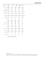 3
3
-
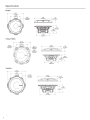 4
4
-
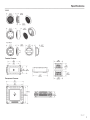 5
5
-
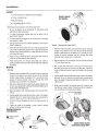 6
6
-
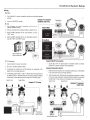 7
7
-
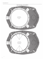 8
8
-
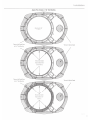 9
9
-
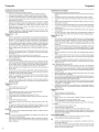 10
10
-
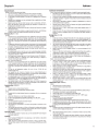 11
11
-
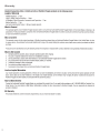 12
12
-
 13
13


Rockford Fosgate T152-S Installation & Operation Manual
- Categoria
- Altoparlanti
- Tipo
- Installation & Operation Manual
in altre lingue
- English: Rockford Fosgate T152-S
- français: Rockford Fosgate T152-S
- español: Rockford Fosgate T152-S
- Deutsch: Rockford Fosgate T152-S
Documenti correlati
-
Rockford Fosgate T1 T-S Installation & Operation Manual
-
 Rockford Fosgate Punch P162S Manuale utente
-
 Rockford Fosgate T3652-S Installation & Operation Manual
-
 Rockford Fosgate PUNCH PM2T-S Installation & Operation Manual
-
Rockford Fosgate power T252-S Installation & Operation Manual
-
 Rockford Fosgate T4652-S Installation & Operation Manual
-
Rockford T165 Manuale utente
-
-
 Rockford Fosgate P152-S Manuale utente
-
 Rockford Fosgate Punch PP8-T Installation & Operation Manual