Sharp LL-T2015 Manuale del proprietario
- Categoria
- TV
- Tipo
- Manuale del proprietario

LCD Monitor
LCD Farbmonitor
Moniteur LCD
Monitor LCD
Monitor LCD
LL-T2015
OPERATION MANUAL
BEDIENUNGSANLEITUNG
MODE D'EMPLOI
MANUALE D'USO
MANUAL DE FUNCIONAMIENTO

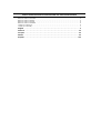
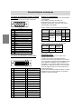
Table of Contents/Inhaltsverzeichnis/Table des matières/Indice/Índice
Notice for Users in the USA . . . . . . . . . . . . . . . . . . . . . . . . . . . . . . . . . . . . . . . . . . . . . . . . . . . . . . . . . . . 3
Notice for Users in Europe . . . . . . . . . . . . . . . . . . . . . . . . . . . . . . . . . . . . . . . . . . . . . . . . . . . . . . . . . . . . 4
Notice for Users in the UK . . . . . . . . . . . . . . . . . . . . . . . . . . . . . . . . . . . . . . . . . . . . . . . . . . . . . . . . . . . . . 5
Notice for Users in Australia . . . . . . . . . . . . . . . . . . . . . . . . . . . . . . . . . . . . . . . . . . . . . . . . . . . . . . . . . . . 5
TCO'03 (LL-T2015-H) . . . . . . . . . . . . . . . . . . . . . . . . . . . . . . . . . . . . . . . . . . . . . . . . . . . . . . . . . . . . . . . . 6
TCO'99 (LL-T2015-B) . . . . . . . . . . . . . . . . . . . . . . . . . . . . . . . . . . . . . . . . . . . . . . . . . . . . . . . . . . . . . . . . 7
English . . . . . . . . . . . . . . . . . . . . . . . . . . . . . . . . . . . . . . . . . . . . . . . . . . . . . . . . . . . . . . . . . . 9
Deutsch . . . . . . . . . . . . . . . . . . . . . . . . . . . . . . . . . . . . . . . . . . . . . . . . . . . . . . . . . . . . . . . . 39
Français . . . . . . . . . . . . . . . . . . . . . . . . . . . . . . . . . . . . . . . . . . . . . . . . . . . . . . . . . . . . . . . . 69
Italiano . . . . . . . . . . . . . . . . . . . . . . . . . . . . . . . . . . . . . . . . . . . . . . . . . . . . . . . . . . . . . . . . . 99
Español. . . . . . . . . . . . . . . . . . . . . . . . . . . . . . . . . . . . . . . . . . . . . . . . . . . . . . . . . . . . . . . . 129

3
EnglishDeutschFrançaisItalianoEspañolEnglish
Notice for Users in the USA
FCC Statement
WARNING – FCC Regulations state that any unauthorized changes or modifications to this equipment
not expressly approved by the manufacturer could void the user's authority to operate this equipment.
Note: This equipment has been tested and found to comply with the limits for a Class B digital device
pursuant to Part 15 of the FCC Rules.
These limits are designed to provide reasonable protection against harmful interference in a
residential installation. This equipment generates, uses and can radiate radio frequency energy and,
if not installed and used in accordance with the instructions, may cause harmful interference to radio
communications. However, there is no guarantee that interference will not occur in a particular
installation. If this equipment does cause harmful interference to radio or television reception, which
can be determined by turning the equipment off and on, the user is encouraged to try to correct the
interference by one or more of the following measures:
- Reorient or relocate the receiving antenna.
- Increase the distance between the equipment and receiver.
- Connect the equipment into an outlet on a circuit different from that to which the receiver is
connected.
- Consult the dealer or an experienced radio/TV technician for help.
Use nothing but the included cables and AC cord to insure compliance with FCC regulation for Class B
computing equipment.
Declaration of Conformity
SHARP LCD Color Monitor LL-T2015-H/LL-T2015-B
This device complies with part 15 of the FCC rules. Operation is subject to the following conditions: (1)
this device may not cause harmful interference, and (2) this device must accept any interference
received, including interference that may cause undesired operation.
Responsible Party: SHARP ELECTRONICS CORPORATION
Sharp Plaza, Mahwah, New Jersey 07430
TEL: 1-800-BE-SHARP
* As an ENERGY STAR
®
Partner, SHARP has determined that this product meets the ENERGY
STA R
®
guidelines for energy efficiency.
This product utilizes tin-lead solder, and fluorescent lamp containing a small amount of mercury.
Disposal of these materials may be regulated due to environmental considerations. For disposal or
recycling information, please contact your local authorities or the Electronics Industries
Alliance: www.eiae.org
IMPORTANT:
To aid in reporting in case of loss or theft, please
record the monitor's model and serial numbers in
the space provided. The numbers are located on
the rear of the monitor.
Model No.:
Serial No.:

4
Notice for Users in Europe
This equipment complies with the requirements of Directives 89/336/EEC and 73/23/EEC as amended
by 93/68/EEC.
Dieses Gerät entspricht den Anforderungen der EG-Richtlinien 89/336/EWG und 73/23/EWG mit
Änderung 93/68/EWG.
Ce matériel répond aux exigences contenues dans les directives 89/336/CEE et 73/23/CEE modifiées
par la directive 93/68/CEE.
Dit apparaat voldoet aan de eisen van de richtlijnen 89/336/EEG en 73/23/EEG, gewijzigd door 93/68/
EEG.
Dette udstyr overholder kravene i direktiv nr. 89/336/EEC og 73/23/EEC med tillæg nr. 93/68/EEC.
Quest' apparecchio è conforme ai requisiti delle direttive 89/336/EEC e 73/23/EEC, come emendata
dalla direttiva 93/68/EEC.
ï
ó ó
Este equipamento obedece às exigências das directivas 89/336/CEE e 73/23/CEE, na sua versão
corrigida pela directiva 93/68/CEE.
Este aparato satisface las exigencias de las Directivas 89/336/CEE y 73/23/CEE, modificadas por
medio de la 93/68/CEE.
Denna utrustning uppfyller kraven enligt riktlinjerna 89/336/EEC och 73/23/EEC så som komplette ras
av 93/68/EEC.
Dette produktet oppfyller betingelsene i direktivene 89/336/EEC og 73/23/EEC i endringen 93/68/EEC.
Tämä laite täyttää direktiivien 89/336/EEC ja 73/23/EEC vaatimukset, joita on muutettu direktiivillä 93/
68/EEC.
CAUTION:
TO PREVENT ELECTRICAL SHOCK, DISCONNECT THE AC CORD BEFORE SERVICING.
CAUTION:
FOR A COMPLETE ELECTRICAL DISCONNECTION, PULL OUT THE MAIN PLUG.
VORSICHT:
UM DIE STROMZUFUHR VOLLSTÄNDIG ZU UNTERBRECHEN, DEN NETZSTECKER HERAUSZIEHEN
ENTFERNEN.
ATTENTION :
POUR UN ARRET TOTAL DE L'APPAREIL, DEBRANCHEZ LA PRISE DU COURANT SECTEUR.
VARNING:
FÖR TOTAL ELEKTRISK URKOPPLING, KOPPLA UR KONTAKTEN OCH.
PRECAUCION:
PARA UNA COMPLETA DESCONEXION ELECTRICA DESENCHUFE LA CLAVIJA DE LA RED.
PRECAUCION:
A FIN DE EVITAR DESCARGAS ELÉCTRICAS, DESCONECTE EL ENCHUFE DE LA RED ANTES DE
REALIZAR CUALQUIER OPERACIÓN DE SERVICIO.
ATTENZIONE:
PER EVITARE FOLGORAZIONI, SCOLLEGATE IL CAVO DI COLLEGAMENTO ALLA RETE IN
ALTERNATA PRIMA DI EFFETTUARE UN INTERVENTO DI SERVIZIO TECNICO.
ATTENZIONE:
PER UNO SCOLLEGAMENTO ELETTRICO COMPLETO, TIRATE FUORI LA SPINA PRINCIPALE.

5
EnglishDeutschFrançaisItalianoEspañolEnglish
Notice for Users in the UK
Notice for Users in Australia
Service Inquiries
Please contact your dealer for service if required or contact Sharp Corporation of Australia on
1 300 13 50 22 for referral to your nearest Sharp authorized Service Center.
FOR CUSTOMERS IN U.K.
IMPORTANT
The wires in this mains lead are coloured in accordance with the following code:
GREEN-AND-YELLOW : Earth
BLUE : Neutral
BROWN : Live
As the colours of the wires in the mains lead of this apparatus may not correspond with the coloured
markings identifying the terminals in your plug proceed as follows:
• The wire which is coloured GREEN-AND-YELLOW must be connected to the terminal in the plug
which is marked by the letter E or by the safety earth or coloured green or green-and-yellow.
• The wire which is coloured BLUE must be connected to the terminal which is marked with the
letter N or coloured black.
• The wire which is coloured BROWN must be connected to the terminal which is marked with the
letter L or coloured red.
Ensure that your equipment is connected correctly. If you are in any doubt consult a qualified
electrician.
"WARNING: THIS APPARATUS MUST BE EARTHED."

6
Congratulations!
The display you have just purchased carries the TCO'03 Displays
label. This means that your display is designed, manufactured and
tested according to some of the strictest quality and environmental
requirements in the world. This makes for a high performance product,
designed with the user in focus that also minimizes the impact on our
natural environment.
Some of the features of the TCO'03 Display requirements:
Ergonomics
• Good visual ergonomics and image quality in order to improve the working environment for the user
and to reduce sight and strain problems. Important parameters are luminance, contrast, resolution,
reflectance, colour rendition and image stability.
Energy
• Energy-saving mode after a certain time – beneficial both for the user and the environment
• Electrical safety
Emissions
• Electromagnetic fields
• Noise emissions
Ecology
• The product must be prepared for recycling and the manufacturer must have a certified environmental
management system such as EMAS or ISO 14 001
• Restrictions on
- chlorinated and brominated flame retardants and polymers
- heavy metals such as cadmium, mercury and lead.
The requirements included in this label have been developed by TCO Development in cooperation with
scientists, experts, users as well as manufacturers all over the world. Since the end of the 1980s TCO
has been involved in influencing the development of IT equipment in a more user-friendly direction. Our
labelling system started with displays in 1992 and is now requested by users and IT-manufacturers all
over the world.
For more information, please visit
www.tcodevelopment.com
LL-T2015-H

7
EnglishDeutschFrançaisItalianoEspañolEnglish
LL-T2015-B
Congratulations!
You have just purchased a TCO'99 approved and labelled product! Your choice has provided you with a
product developed for professional use. Your purchase has also contributed to reducing the burden on
the environment and also to the further development of environmentally adapted electronics products.
Why do we have environmentally labelled computers?
In many countries, environmental labelling has become an established method for encouraging the
adaptation of goods and services to the environment. The main problem, as far as computers and other
electronics equipment are concerned, is that environmentally harmful substances are used both in the
products and during their manufacture. Since it is not so far possible to satisfactorily recycle the majority
of electronics equipment, most of these potentially damaging substances sooner or later enter nature.
There are also other characteristics of a computer, such as energy consumption levels, that are important
from the viewpoints of both the work (internal) and natural (external) environments. Since all methods of
electricity generation have a negative effect on the environment (e.g. acidic and climate-influencing
emissions, radioactive waste), it is vital to save energy. Electronics equipment in offices is often left
running continuously and thereby consumes a lot of energy.
What does labelling involve?
This product meets the requirements for the TCO'99 scheme which provides for international and
environmental labelling of personal computers. The labelling scheme was developed as a joint effort by
the TCO (The Swedish Confederation of Professional Employees), Svenska Naturskyddsforeningen
(The Swedish Society for Nature Conservation) and Statens Energimyndighet (The Swedish National
Energy Administration).
Approval requirements cover a wide range of issues: environment, ergonomics, usability, emission of
electric and magnetic fields, energy consumption and electrical and fire safety.
The environmental demands impose restrictions on the presence and use of heavy metals, brominated
and chlorinated flame retardants, CFCs (freons) and chlorinated solvents, among other things. The
product must be prepared for recycling and the manufacturer is obliged to have an environmental policy
which must be adhered to in each country where the company implements its operational policy.
The energy requirements include a demand that the computer and/or display, after a certain period of
inactivity, shall reduce its power consumption to a lower level in one or more stages. The length of time to
reactivate the computer shall be reasonable for the user.
Labelled products must meet strict environmental demands, for example, in respect of the reduction of
electric and magnetic fields, physical and visual ergonomics and good usability.
Below you will find a brief summary of the environmental requirements met by this product. The complete
environmental criteria document may be ordered from:
TCO Development
SE-114 94 Stockholm, Sweden
Fax: +46 8 782 92 07
Email (Internet): [email protected]
Current information regarding TCO'99 approved and labelled products may also be
obtained via the Internet, using the address: http://www.tco-info.com/

8
Environmental requirements
Flame retardants
Flame retardants are present in printed circuit boards, cables, wires, casings and housings. Their
purpose is to prevent, or at least to delay the spread of fire. Up to 30% of the plastic in a computer casing
can consist of flame retardant substances. Most flame retardants contain bromine or chloride, and those
flame retardants are chemically related to another group of environmental toxins, PCBs. Both the flame
retardants containing bromine or chloride and the PCBs are suspected of giving rise to severe health
effects, including reproductive damage in fish-eating birds and mammals, due to the bio-accumulative*
processes. Flame retardants have been found in human blood and researchers fear that disturbances in
foetus development may occur.
The relevant TCO'99 demand requires that plastic components weighing more than 25 grams must not
contain flame retardants with organically bound bromine or chlorine. Flame retardants are allowed in the
printed circuit boards since no substitutes are available.
Cadmium**
Cadmium is present in rechargeable batteries and in the colour-generating layers of certain computer
displays. Cadmium damages the nervous system and is toxic in high doses. The relevant TCO'99
requirement states that batteries, the colour-generating layers of display screens and the electrical or
electronics components must not contain any cadmium.
Mercury**
Mercury is sometimes found in batteries, relays and switches. It damages the nervous system and is toxic
in high doses. The relevant TCO'99 requirement states that batteries may not contain any mercury. It
also demands that mercury is not present in any of the electrical or electronics components associated
with the labelled unit. There is however one exception. Mercury is, for the time being, permitted in the
back light system of flat panel monitors as there today is no commercially available alternative. TCO
aims on removing this exception when a mercury free alternative is available.
CFCs (freons)
The relevant TCO'99 requirement states that neither CFCs nor HCFCs may be used during the
manufacture and assembly of the product. CFCs (freons) are sometimes used for washing printed circuit
boards. CFCs break down ozone and thereby damage the ozone layer in the stratosphere, causing
increased reception on earth of ultraviolet light with e.g. increased risks of skin cancer (malignant
melanoma) as a consequence.
Lead**
Lead can be found in picture tubes, display screens, solders and capacitors. Lead damages the nervous
system and in higher doses, causes lead poisoning. The relevant TCO'99 requirement permits the
inclusion of lead since no replacement has yet been developed.
*
Bio-accumulative is defined as substances which accumulate within living organisms.
**
Lead, Cadmium and Mercury are heavy metals which are Bio-accumulative.

9
EnglishDeutschFrançaisItalianoEspañolEnglish
Table of Contents
Tips and safety precautions . . . . . . . . . . . . . . . . . . . . . . . . . . . . . . . . . . . . . . . . . . . . . . . . . . . . . . . . . . . . 10
Product description . . . . . . . . . . . . . . . . . . . . . . . . . . . . . . . . . . . . . . . . . . . . . . . . . . . . . . . . . . . . . . . . . . 11
Height adjustment, angle adjustment . . . . . . . . . . . . . . . . . . . . . . . . . . . . . . . . . . . . . . . . . . . . . . . . . . . . 12
Connecting the monitor and turning the monitor on and off . . . . . . . . . . . . . . . . . . . . . . . . . . . . . . . . . . . 13
Connecting the monitor to a computer . . . . . . . . . . . . . . . . . . . . . . . . . . . . . . . . . . . . . . . . . . . . . . . . 14
Connecting the monitor to a power source . . . . . . . . . . . . . . . . . . . . . . . . . . . . . . . . . . . . . . . . . . . . . 15
Turning the power on . . . . . . . . . . . . . . . . . . . . . . . . . . . . . . . . . . . . . . . . . . . . . . . . . . . . . . . . . . . . . . 16
Changing between input terminals . . . . . . . . . . . . . . . . . . . . . . . . . . . . . . . . . . . . . . . . . . . . . . . . . . . 16
Turning the power off . . . . . . . . . . . . . . . . . . . . . . . . . . . . . . . . . . . . . . . . . . . . . . . . . . . . . . . . . . . . . . 17
Adjusting the screen display . . . . . . . . . . . . . . . . . . . . . . . . . . . . . . . . . . . . . . . . . . . . . . . . . . . . . . . . . . . 18
Adjustment value reset . . . . . . . . . . . . . . . . . . . . . . . . . . . . . . . . . . . . . . . . . . . . . . . . . . . . . . . . . . . . . 18
Adjustment lock function . . . . . . . . . . . . . . . . . . . . . . . . . . . . . . . . . . . . . . . . . . . . . . . . . . . . . . . . . . . 18
Adjusting the backlight . . . . . . . . . . . . . . . . . . . . . . . . . . . . . . . . . . . . . . . . . . . . . . . . . . . . . . . . . . . . . 18
Setting display mode . . . . . . . . . . . . . . . . . . . . . . . . . . . . . . . . . . . . . . . . . . . . . . . . . . . . . . . . . . . . . . 19
Checking product information . . . . . . . . . . . . . . . . . . . . . . . . . . . . . . . . . . . . . . . . . . . . . . . . . . . . . . . 19
Adjusting the screen display (With analog connection) . . . . . . . . . . . . . . . . . . . . . . . . . . . . . . . . . . . . . . 20
Automatic screen adjustment . . . . . . . . . . . . . . . . . . . . . . . . . . . . . . . . . . . . . . . . . . . . . . . . . . . . . . . . 20
Manual screen adjustment . . . . . . . . . . . . . . . . . . . . . . . . . . . . . . . . . . . . . . . . . . . . . . . . . . . . . . . . . . 21
Adjusting the screen display (With digital connection) . . . . . . . . . . . . . . . . . . . . . . . . . . . . . . . . . . . . . . 25
Monitor care . . . . . . . . . . . . . . . . . . . . . . . . . . . . . . . . . . . . . . . . . . . . . . . . . . . . . . . . . . . . . . . . . . . . . . . . 28
Monitor care . . . . . . . . . . . . . . . . . . . . . . . . . . . . . . . . . . . . . . . . . . . . . . . . . . . . . . . . . . . . . . . . . . . . . 28
Storage . . . . . . . . . . . . . . . . . . . . . . . . . . . . . . . . . . . . . . . . . . . . . . . . . . . . . . . . . . . . . . . . . . . . . . . . . 28
Troubleshooting . . . . . . . . . . . . . . . . . . . . . . . . . . . . . . . . . . . . . . . . . . . . . . . . . . . . . . . . . . . . . . . . . . 28
Information for customers on environmentally friendly disposal of this SHARP product . . . . . . . . . 29
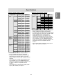
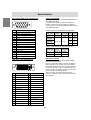
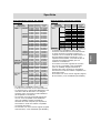
Specifications . . . . . . . . . . . . . . . . . . . . . . . . . . . . . . . . . . . . . . . . . . . . . . . . . . . . . . . . . . . . . . . . . . . . . . . 30
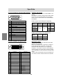
Installing set-up information and the ICC profile (For Windows) . . . . . . . . . . . . . . . . . . . . . . . . . . . . . . . 33
Information about the ColorSync profile (For MacOS) . . . . . . . . . . . . . . . . . . . . . . . . . . . . . . . . . . . . . . . 36
Instructions for attaching a VESA-compliant arm . . . . . . . . . . . . . . . . . . . . . . . . . . . . . . . . . . . . . . . . . . . 37

10
Tips and safety precautions
The Power Cord
- Do not damage the power cord nor place heavy
objects on it, stretch it or over bend it. Also, do
not add extension cords. Damage to the cord
may result in fire or electric shock.
- Use only the power cord supplied with the monitor.
- Insert the power plug directly into the AC outlet.
Adding an extension cord may lead to fire as a
result of overheating.
- Do not remove or insert the power plug with wet
hands. Doing so could result in electric shock.
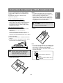
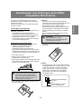
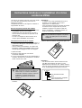
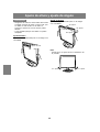
Monitor and accessory checklist
- Please check that the following items are
included in the package:
- LCD monitor (1)
- Analog signal cable (1)
(model name: QCNW-1041MPZZ)
- Digital signal cable (1)
(model name: QCNW-1088MPZZ)
- CD-ROM (1)
- Operation manual (1)
Notes:
- The analog signal cable (DVI-I29 pin - mini D-
sub15 pin) is to be purchased separately.
(model name: NL-C02E)
- The 2-input cable (DVI-I29 pin - DVI-D24 pin/
mini
D-sub15 pin) is to be purchased separately.
(model name: NL-C03J)
- Be sure to use cables that are less than 3 m in
length.
- You are advised to retain the carton in case the
monitor needs to be transported.
- Sharp Corporation holds authorship rights to the
Utility Disk program. Do not reproduce it without
permission.
- The shape of the supplied accessories may not
be exactly same as shown in this manual.
Manual Scope
- In this manual, Microsoft Windows XP will be
referred to as "Windows XP", Microsoft Windows
Millennium as "Windows Me", Microsoft
Windows 2000 as "Windows 2000", Microsoft
Windows 98 as "Windows 98", Microsoft
Windows 95 as "Windows 95", and Microsoft
Windows Version 3.1 as "Windows 3.1". When
there is no need to distinguish between
programs, the term "Windows" will be used.
- Microsoft and Windows are registered
trademarks of Microsoft Corporation.
- Macintosh is a registered trademark of Apple
Computer, Inc.
- All other brand and product names are
trademarks or registered trademarks of their
respective holders.
- The TFT color LCD panel used in this monitor is
made with the application of high precision
technology. However, there may be minute
points on the screen where pixels never light or
are permanently lit. Also, if the screen is viewed
from an acute angle there may be uneven colors
or brightness. Please note that these are not
malfunctions but common phenomena of LCDs
and will not affect the performance of the
monitor.
- Do not display a still picture for a long time, as
this could cause an afterimage to remain.
- If the brightness is adjusted to the minimum
setting it may be difficult to see the screen.
- The quality of the computer signal may influence
the quality of the display. We recommend using
a computer able to emit high quality video
signals.
- Never rub or tap the monitor with hard objects.
- Please understand that Sharp Corporation bears
no responsibility for errors made during use by
the customer or a third party, nor for any other
malfunctions or damage to this product arising
during use, except where indemnity liability is
recognized under law.
- This monitor and its accessories may be
upgraded without advance notice.
Location
- Do not use the monitor where ventilation is poor,
where there is a lot of dust, where humidity is high,
or where the monitor may come into contact with
oil or steam, as this could lead to fire.
- Ensure that the monitor does not come into
contact with water or other fluids. Ensure that no
objects such as paper clips or pins enter the
monitor as this could lead to fire or electric
shock.
- Do not place the monitor on top of unstable
objects or in unsafe places. Do not allow the
monitor to come into contact with strong shocks
or vibrations. Causing the monitor to fall or
topple over may damage it.
- Do not use in places where the monitor will be
subject to direct sunlight, near heating
equipment or anywhere else where there is
likelihood of high temperature, as this may lead
to generation of excessive heat and outbreak of
fire.
- When carrying the monitor, firmly grasp both the
display and stand section. If the monitor is lifted
by the display only, the stand may abruptly pop
out or move, and this could lead to injury. If the
monitor is inclined, the stand may move and
cause injury.
- Be careful not to allow your fingers to be
pinched between the display and stand.
(Especially in the area of attachment.)

11
EnglishDeutschFrançaisItalianoEspañolEnglish
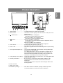
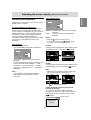
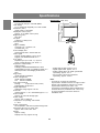
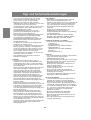
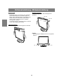
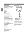
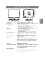
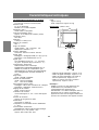
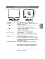
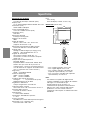
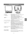
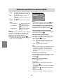
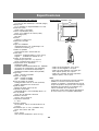
Product description
1
2 3 4 5 6
7
11
12
10
8
9
1. INPUT button .............................. To switch between the signal's input terminals.
2. MENU button .............................. This button is used to pop-up, select and close the OSD (On Screen
Display) Menu.
3.
/ MODE button ........................ When the OSD Menu is displayed:
This button is used to select menu options.
When the OSD Menu is not displayed:
This button is used to set DISPLAY MODE.
4. buttons ................................ When the OSD Menu is displayed:
These buttons are used to select an option or adjust the value of
the selected option.
When the OSD Menu is not displayed:
These buttons are used to adjust backlight brightness.
5. Power button ............................... Pressing this button turns the power on.
Press the button again to turn the power off.
6. Power LED.................................. This LED is lit green when in use and orange when in power-saving
mode.
7.
DVI-I input terminal (INPUT-2) ......
The computer's digital RGB output terminal or analog RGB output
terminal can be connected here.
For a digital signal input: It can be connected to a computer with a
DVI-compatible output terminal (DVI-D24 pin or DVI-I29 pin) and
which has UXGA output ability. Depending on the computer to be
connected, correct display may or may not be possible.
8.
Analog RGB input terminal (INPUT-1)
.... The analog signal cable is connected here. The analog signal cable
included should be used.
9. Security lock anchor ................... By connecting a security lock (commercially available) to the
security lock anchor, the monitor is fixed so that it cannot be
transported.
The security slot works in conjunction with Kensington Micro Saver
Security Systems.
10. Power terminal
11. Main power switch
12. Ventilation openings .................. Note: Never block the ventilation openings as this may lead to
overheating inside the monitor and result in malfunction.

12
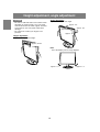
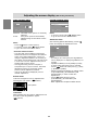
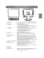
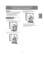
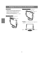
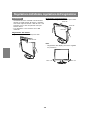
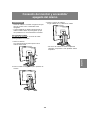
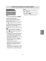
Height adjustment, angle adjustment
CAUTION!
- Be sure to hold both sides of the monitor when
adjusting the viewing angle. The LCD panel
used in this monitor is made of glass. Pressure
from hands on the LCD panel could cause
damage.
- Be careful not to allow your fingers to be
pinched.
Height adjustment
Adjust to an easy to view height.
approx. 60 mm
Angle adjustment
Adjust to an easy to view angle.
Note:
- Tilt of the display can be finely adjusted.
approx. 1.0°
approx. 1.0°
approx. 30°
approx. 45°
approx. 5°
approx. 45°

13
EnglishDeutschFrançaisItalianoEspañolEnglish
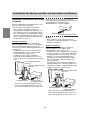
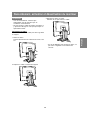
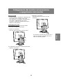
Connecting the monitor and turning the monitor on and off
CAUTION!
- When connecting, ensure that both the monitor
and computer are switched off.
- Be careful not to over bend the cable or add
extension cords as this could lead to a
malfunction.
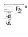
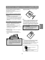
Cable storage
If necessary, excess cable can be housed in the
stand.
1.Remove the cover.
Gently pull the top of the cover towards yourself.
2.Run cable along the back of the stand.
3.Refit the cover.
Be careful not to pinch the cable.
- If the cover is hard to refit, do not force it.
Check whether cables are trapped.

14
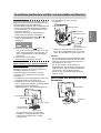
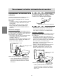
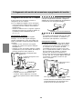
Connecting the monitor and turning the monitor on and off
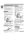
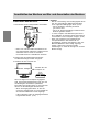
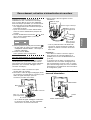
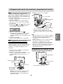
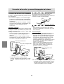
Digital connection
Connect the accessory digital signal cable to the
digital RGB output terminal of the computer.
- The monitor has an input for connecting to a
computer with a DVI-compatible output
connector (DVI-D24 pin or DVI-I29 pin) and
UXGA output capability. (Depending on the type
of computer to be connected, the display may
not work correctly.)
- Use the accessory digital signal cable.
If using other commercially available digital
signal cables, correct display may not be
achieved.
- Paying attention to connector direction, firmly
insert the signal cable to terminal, and then
tighten the screws at both sides.
Set the monitor as follows when establishing a
digital connection with a Power Mac using an ADC-
DVI adapter made by Belkin. (Operation has been
checked with the Power Mac G4 M7627J/A.)
- Perform settings with the Power Mac power
supply off.
1.After connecting the power cord, turn on the
monitor's main power.
2.Press the button and button simultaneously,
and while doing this press the power button (i.e.
turn the power on).
MAC DIGITAL
INPUT-2 OFF ON
3.Set to [ON] with the buttons.
- Do not set to [ON] if you are not using a Belkin
ADC-DVI adapter, as this may result in
incorrect display.
4.Press the MENU button.
This completes setting.
Digital signal cable
Digital RGB output
terminal
DVI-I input terminal
(INPUT-2)
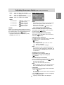
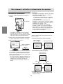
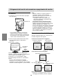
Connecting the monitor to a computer
The accessory signal cable enables connection of
two computers.
(One analog and one digital connection.)
-
The separately sold 2-input cable enables connection of
two computers to the DVI-I input terminal.
- When using the 2-input cable, set the
connecting input terminal [INPUT-2] to [2LINES]
under the MODE SELECT-2 Menu. (p.24, 27)
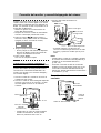
Analog connection
Connect the accessory analog signal cable, or
separately-sold analog signal cable (model name:
NL-C02E) to the analog RGB output terminal of
the computer.
- Connect the accessory analog signal cable to
the analog RGB input terminal (INPUT-1).
- Connect the separately-sold analog signal cable
(model name: NL-C02E) to the DVI-I input
terminal (INPUT-2).
- Paying attention to connector direction, firmly
insert the signal cable to terminal, and then
tighten the screws at both sides.
If connecting to a D-sub15 pin 2 row Apple Power
Macintosh, attach a Macintosh conversion adapter
(commercially available) to the analog signal cable.
Note:
- If connecting to the Sun Ultra series, a
conversion adapter (commercially available)
may be required.
Analog signal cable
Analog RGB output
terminal
DVI-I input terminal
(INPUT-2)
Analog RGB
input terminal
(INPUT-1)
Macintosh conversion adapter

15
EnglishDeutschFrançaisItalianoEspañolEnglish
Connecting the monitor and turning the monitor on and off
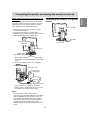
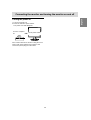
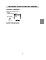
Connecting the monitor to a power
source
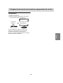
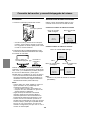
When connecting using a separately sold 2-
input cable
The separately sold 2-input cable (model name:
NL-C03J) enables connection between the DVI-I
input terminal on the monitor and the two PCs.
(One analog and one digital connection.)
1.Connect the 2-input cable to the DVI-I input
terminal of the monitor.
2.Connect the accessory or commercially
available analog signal cable and the accessory
digital signal cable to the 2-input cable.
- When using commercially available analog
signal cable, both ends should be mini D-sub
15 pin.
3.Connect each signal cable to the computers.
- Paying attention to connector orientation,
firmly insert the signal cable into the PC, and
then tighten the screws at both sides.
Notes:
- When using the 2-input cable, set the
connecting input terminal [INPUT-2] to [2LINES]
under the MODE SELECT-2 Menu. (p.24, 27)
- The monitor connected to the 2-input cable by
analog connection may not be automatically
recognized and setup under Plug & Play.
Perform storage of setup information manually.
(p.33)
DVI-D24 pin
2-input cable
(purchased separately)
mini D-sub15 pin
DVI-I input terminal
(INPUT-2)
Digital RGB output terminal
Digital signal cable
Analog signal cable
Analog RGB
output terminal
Power terminal
Power cord
AC outlet

16
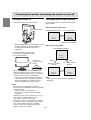
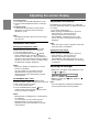
Turning the power on
1.Turn on the main power of the monitor.
- When switching the main power switch on and
off, always wait for an interval of at least 5
seconds. Rapid switching may result in
malfunction.
2.Press the monitor's power button.
The power LED will light up orange.
3.Turn on the computer.
ON
When a signal is input from the computer, the
power LED lights up green, and the screen is
displayed. (After power is turned on, it may take
a little time until the screen is displayed.)
- If the input terminal to which the computer is
connected has not been selected, the screen
will not be displayed. If necessary, perform
input terminal switching. (right column)
Notes:
- When using an analog signal, perform an
automatic screen adjustment under the following
conditions (p.20):
- Using the monitor for the first time.
- After having changed the system settings
during use.
- Depending on the type of computer or OS, you
may need to install the monitor set-up
information on your system. (p.33)
- When connecting to a notebook, if the notebook
computer's screen is set to display at the same
time, the MS-DOS screen may not display
properly. In this case, change the setting to
display only the LCD monitor.
Turn on the
computer power
supply.
Press power button.
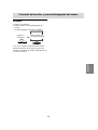
Changing between input terminals
Use the INPUT button to switch between signal
input terminals.
When not using a 2-input cable
Analog RGB input terminal
DVI-I input terminal
INPUT-1
<ANALOG>
INPUT-2
< >
INPUT
<ANALOG> or <DIGITAL>
When using a 2-input cable
Analog RGB input terminal
INPUT2-A
<ANALOG>
INPUT2-D
<DIGITAL>
INPUT
INPUT-1
<ANALOG>
INPUT
INPUT
Note:
- When there is no input signal, [NO SIGNAL] is
displayed.
Connecting the monitor and turning the monitor on and off
Main power switch
DVI-I input terminal
(analog)
DVI-I input terminal
(digital)

17
EnglishDeutschFrançaisItalianoEspañolEnglish
Turning the power off
1. Turn the computer off.
2.Press the monitor's power button.
The power LED will disappear.
OFF
If the monitor will not be used for a long time, turn
off the main power switch of the monitor, and
remove the power plug from the outlet.
Press power button.
Turn the computer
off.
Connecting the monitor and turning the monitor on and off

18
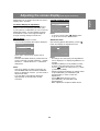
Adjusting the screen display
For analog signal
1.First perform an automatic adjustment. (p.20)
2.Perform manual adjustment where necessary.
(p.21)
For digital signal
The monitor can generally be used without
adjustment. If necessary perform manual
adjustment. (p.25)
Note:
- All adjustments will be saved even after turning
the power off.
Adjustment value reset
Resetting all adjustment values
All adjustment values can be returned to their
original ex-factory values in one command.
1. Turn off the monitor power.
2.Press the MENU button and the / MODE
button simultaneously, and while doing this
press the power button (i.e. turn the power on).
Continue to press the buttons until [ALL RESET]
appears on the screen. Reset is complete when
the displayed message disappears.
Notes:
- While [ALL RESET] is displayed, the control
buttons are disabled.
- It is not possible to reset values when the
adjustment lock is in place. Remove the
adjustment lock before attempting to operate
control buttons.
ADJUSTMENT Menu reset
Settings of items in the ADJUSTMENT Menu
(CLOCK, PHASE, H-POS, V-POS) can be returned
to their original ex-factory values.
1.Turn on the monitor power.
2. Press the MENU button and the button
simultaneously. When [RESET] appears on the
screen, the reset is complete.
Notes:
- While [RESET] is displayed, the control buttons
are disabled.
- It is not possible to reset values when the
adjustment lock is in place. Remove the
adjustment lock before attempting to operate
control buttons.
Adjustment lock function
By disabling the control buttons (i.e. setting the
lock) any attempted changes to adjusted values will
be voided.
1. Turn off the monitor power.
2.While pressing the MENU button, press the
power button (i.e. turn the power on).
Continue to press the buttons until
[
ADJUSTMENT LOCKED
] appears on the
screen. The lock is set when the message is
displayed.
Note:
- When the lock is in place, all buttons other than
the power button are disabled.
Adjustment lock release
1. Turn off the monitor power.
2.While pressing the MENU button, press the
power button (i.e. turn the power on).
Continue to press the buttons until
[
ADJUSTMENT UNLOCKED
] appears on the
screen. The lock is released when the message
is displayed.
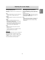
Adjusting the backlight
1.Without the OSD Menu being displayed, press
the or the button.
BR
I
GHT 31
+
-
2.Adjust by pressing the button (darker) or
button (lighter).
Note:
- On Screen display for adjustment disappears
several seconds after the last operation.

19
EnglishDeutschFrançaisItalianoEspañolEnglish
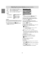
Setting display mode
Color tone or brightness can be changed with one
command.
STD
Displays image with the color tone results from
original scheme of liquid crystal panel.
OFFICE
Display brightness is lowered. (This mode saves
power.)
sRGB
sRGB is international standard of color
representation specified by IEC (International
Electrotechnical Commission).
Color conversion is made in taking account of
liquid crystal's characteristics and represents
color tone close to its original image.
VIVID
Displays an image with dynamic and vivid
primary colors.
- If [DISPLAY MODE] is set to [sRGB] or [VIVID],
[WHITE BALANCE] is set to [STD].
How to set
Press the / MODE button when the OSD Menu is
not displayed.
Each time the button is pressed the next menu
item appears. (STD OFFICE sRGB VIVID
STD)
On Screen display for adjustment disappears
several seconds after the last operation.
Checking product information
A model name (MODEL), a serial no. (S/N), and
usage time (USAGE TIME) of the monitor can be
checked.
1.Turn the power off.
2.While pressing the / MODE button, press the
monitor's power button (i.e. turn the power on).
3.Checking done: MENU button
Note:
- Please note that the indication of usage time at
purchase may not be 0 (zero), as a result of
factory inspection and other activities during
manufacture.
Adjusting the screen display

20
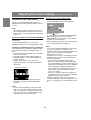
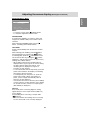
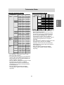
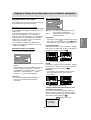
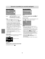
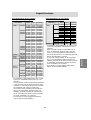
Adjusting the screen display (With analog connection)
Automatic screen adjustment
Options in the ADJUSTMENT Menu can be
adjusted automatically (CLOCK, PHASE, H-POS,
V-POS).
Note:
- When setting up this monitor for the first time or
after having changed an aspect of the current
system, perform an automatic screen adjustment
before use.
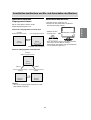
On Screen Display for the automatic adjustment
First display an image that makes the entire
screen light.
If you are using Windows, you can use the
Adjustment Pattern on the accompanying CD-ROM.
Opening the Adjustment Pattern (for Windows)
This explanation is for Windows 95/98/2000/Me/
XP, and assumes that the CD-ROM drive is "D"
drive.
1.Load the accessory CD-ROM into the CD-ROM
drive of the computer.
2.Open [My Computer] and select CD-ROM. If
using Windows 3.1, open [File Manager] and
choose "D" drive.
3.Double click on [Adj_uty.exe] to run the
Adjustment Program. The Adjustment Pattern
will appear.
Adjustment Pattern
After completing the adjustments, press the
computer's [Esc] key to exit the Adjustment
Program.
Note:
- If your computer's display mode is set to 65K
colors, you may see the different color levels in
each color pattern or the gray scale may look
colored. (This is due to the specification of the
input signal and is not a malfunction.)
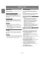
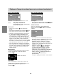
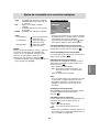
Adjusting the screen automatically
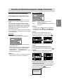
1.Press the MENU button.
The ADJUSTMENT Menu will be displayed.
ADJUSTMENT
MANUAL AUTO
CLOCK 127
PHASE 0
H-POS 250
V-POS 48
INPUT-1 ANALOG
1600 x 1200 V:60Hz H:75.0kHz
+
-
+
-
+
-
+
-
2.Press the button.
The screen will become dark and [ADJUSTING]
will be displayed. After a few seconds the
ADJUSTMENT Menu will return. (The automatic
adjustment is now complete.)
3.Press the MENU button 5 times to make the OSD
(On Screen Display) Menu disappear.
Notes:
- In most cases automatic adjustment is sufficient.
- It may not be possible to achieve correct
adjustment with the first automatic adjustment. In
such a case, try repeating the automatic
adjustment 2 or 3 times.
- If necessary due to any of the following, manual
adjustments (p.21) can be performed after the
automatic adjustment:
- When further fine adjustment is needed.
- When [OUT OF ADJUST] is displayed. (When
the screen displays an entirely dark image, the
automatic screen adjustment may be disabled.
When making an automatic adjustment, be
sure to either use the Adjustment Pattern or try
displaying an image that makes the entire
screen very bright.)
- When the computer's video input signals are
Composite Sync or Sync on Green. (Automatic
adjustments may not be possible.)
- Automatic adjustment may not be achieved
correctly depending on what is displayed on the
screen - moving pictures or the MS-DOS prompt
etc.
La pagina sta caricando ...
La pagina sta caricando ...
La pagina sta caricando ...
La pagina sta caricando ...
La pagina sta caricando ...
La pagina sta caricando ...
La pagina sta caricando ...
La pagina sta caricando ...
La pagina sta caricando ...
La pagina sta caricando ...
La pagina sta caricando ...
La pagina sta caricando ...
La pagina sta caricando ...
La pagina sta caricando ...
La pagina sta caricando ...
La pagina sta caricando ...
La pagina sta caricando ...
La pagina sta caricando ...
La pagina sta caricando ...
La pagina sta caricando ...
La pagina sta caricando ...
La pagina sta caricando ...
La pagina sta caricando ...
La pagina sta caricando ...
La pagina sta caricando ...
La pagina sta caricando ...
La pagina sta caricando ...
La pagina sta caricando ...
La pagina sta caricando ...
La pagina sta caricando ...
La pagina sta caricando ...
La pagina sta caricando ...
La pagina sta caricando ...
La pagina sta caricando ...
La pagina sta caricando ...
La pagina sta caricando ...
La pagina sta caricando ...
La pagina sta caricando ...
La pagina sta caricando ...
La pagina sta caricando ...
La pagina sta caricando ...
La pagina sta caricando ...
La pagina sta caricando ...
La pagina sta caricando ...
La pagina sta caricando ...
La pagina sta caricando ...
La pagina sta caricando ...
La pagina sta caricando ...
La pagina sta caricando ...
La pagina sta caricando ...
La pagina sta caricando ...
La pagina sta caricando ...
La pagina sta caricando ...
La pagina sta caricando ...
La pagina sta caricando ...
La pagina sta caricando ...
La pagina sta caricando ...
La pagina sta caricando ...
La pagina sta caricando ...
La pagina sta caricando ...
La pagina sta caricando ...
La pagina sta caricando ...
La pagina sta caricando ...
La pagina sta caricando ...
La pagina sta caricando ...
La pagina sta caricando ...
La pagina sta caricando ...
La pagina sta caricando ...
La pagina sta caricando ...
La pagina sta caricando ...
La pagina sta caricando ...
La pagina sta caricando ...
La pagina sta caricando ...
La pagina sta caricando ...
La pagina sta caricando ...
La pagina sta caricando ...
La pagina sta caricando ...
La pagina sta caricando ...
La pagina sta caricando ...
La pagina sta caricando ...
La pagina sta caricando ...
La pagina sta caricando ...
La pagina sta caricando ...
La pagina sta caricando ...
La pagina sta caricando ...
La pagina sta caricando ...
La pagina sta caricando ...
La pagina sta caricando ...
La pagina sta caricando ...
La pagina sta caricando ...
La pagina sta caricando ...
La pagina sta caricando ...
La pagina sta caricando ...
La pagina sta caricando ...
La pagina sta caricando ...
La pagina sta caricando ...
La pagina sta caricando ...
La pagina sta caricando ...
La pagina sta caricando ...
La pagina sta caricando ...
La pagina sta caricando ...
La pagina sta caricando ...
La pagina sta caricando ...
La pagina sta caricando ...
La pagina sta caricando ...
La pagina sta caricando ...
La pagina sta caricando ...
La pagina sta caricando ...
La pagina sta caricando ...
La pagina sta caricando ...
La pagina sta caricando ...
La pagina sta caricando ...
La pagina sta caricando ...
La pagina sta caricando ...
La pagina sta caricando ...
La pagina sta caricando ...
La pagina sta caricando ...
La pagina sta caricando ...
La pagina sta caricando ...
La pagina sta caricando ...
La pagina sta caricando ...
La pagina sta caricando ...
La pagina sta caricando ...
La pagina sta caricando ...
La pagina sta caricando ...
La pagina sta caricando ...
La pagina sta caricando ...
La pagina sta caricando ...
La pagina sta caricando ...
La pagina sta caricando ...
La pagina sta caricando ...
La pagina sta caricando ...
La pagina sta caricando ...
La pagina sta caricando ...
La pagina sta caricando ...
La pagina sta caricando ...
La pagina sta caricando ...
La pagina sta caricando ...
La pagina sta caricando ...
La pagina sta caricando ...
-
 1
1
-
 2
2
-
 3
3
-
 4
4
-
 5
5
-
 6
6
-
 7
7
-
 8
8
-
 9
9
-
 10
10
-
 11
11
-
 12
12
-
 13
13
-
 14
14
-
 15
15
-
 16
16
-
 17
17
-
 18
18
-
 19
19
-
 20
20
-
 21
21
-
 22
22
-
 23
23
-
 24
24
-
 25
25
-
 26
26
-
 27
27
-
 28
28
-
 29
29
-
 30
30
-
 31
31
-
 32
32
-
 33
33
-
 34
34
-
 35
35
-
 36
36
-
 37
37
-
 38
38
-
 39
39
-
 40
40
-
 41
41
-
 42
42
-
 43
43
-
 44
44
-
 45
45
-
 46
46
-
 47
47
-
 48
48
-
 49
49
-
 50
50
-
 51
51
-
 52
52
-
 53
53
-
 54
54
-
 55
55
-
 56
56
-
 57
57
-
 58
58
-
 59
59
-
 60
60
-
 61
61
-
 62
62
-
 63
63
-
 64
64
-
 65
65
-
 66
66
-
 67
67
-
 68
68
-
 69
69
-
 70
70
-
 71
71
-
 72
72
-
 73
73
-
 74
74
-
 75
75
-
 76
76
-
 77
77
-
 78
78
-
 79
79
-
 80
80
-
 81
81
-
 82
82
-
 83
83
-
 84
84
-
 85
85
-
 86
86
-
 87
87
-
 88
88
-
 89
89
-
 90
90
-
 91
91
-
 92
92
-
 93
93
-
 94
94
-
 95
95
-
 96
96
-
 97
97
-
 98
98
-
 99
99
-
 100
100
-
 101
101
-
 102
102
-
 103
103
-
 104
104
-
 105
105
-
 106
106
-
 107
107
-
 108
108
-
 109
109
-
 110
110
-
 111
111
-
 112
112
-
 113
113
-
 114
114
-
 115
115
-
 116
116
-
 117
117
-
 118
118
-
 119
119
-
 120
120
-
 121
121
-
 122
122
-
 123
123
-
 124
124
-
 125
125
-
 126
126
-
 127
127
-
 128
128
-
 129
129
-
 130
130
-
 131
131
-
 132
132
-
 133
133
-
 134
134
-
 135
135
-
 136
136
-
 137
137
-
 138
138
-
 139
139
-
 140
140
-
 141
141
-
 142
142
-
 143
143
-
 144
144
-
 145
145
-
 146
146
-
 147
147
-
 148
148
-
 149
149
-
 150
150
-
 151
151
-
 152
152
-
 153
153
-
 154
154
-
 155
155
-
 156
156
-
 157
157
-
 158
158
-
 159
159
-
 160
160


Sharp LL-T2015 Manuale del proprietario
- Categoria
- TV
- Tipo
- Manuale del proprietario
in altre lingue
- English: Sharp LL-T2015 Owner's manual
- français: Sharp LL-T2015 Le manuel du propriétaire
- español: Sharp LL-T2015 El manual del propietario
- Deutsch: Sharp LL-T2015 Bedienungsanleitung
Documenti correlati
-
Sharp LL-T17D4 Manuale utente
-
-
-
-
-
-
-
-
-