DJ-Tech i-Mix Reload MKII Manuale utente
- Categoria
- Apparecchiature musicali supplementari
- Tipo
- Manuale utente

DJ Control Interface with Audio I/O
USER MANUAL
MANUEL D’UTILISATION
BENUTZERHANDBUCH
GEBRUIKSAANWIJZING
MANUAL DE INSTRUCCIONES
MANUALE DI ISTRUZIONI
(English)
(Français)
(Deutsch)
(Nederlands)
(Español)
(Italiano)
01~04
05~08
09~12
13~16
17~20
21~24

ESPAÑOL
ITALIANO
NEDERLANDS
ENGLISH
FRANÇAIS
DEUTSCH
1. Read these instructions.
2. Keep these instructions.
3. Heed all warnings.
4. Follow all instructions.
5. Do not use the apparatus near water.
6. Clean only with dry cloth.
7. Do not block any ventilation openings. Install in accordance with the manufacturer’s instructions.
8. Do not install near any heat sources such as radiators, heat registers, stoves, or other apparatus (including
amplifiers) that produce heat.
9. Do not defeat the safety purpose of the polarized or grounding-type plug. A polarized plug has two blades
with one wider than the other. A grounding- type plug has two blades and a third grounding prong. The wide
blade or the third prong is provided for your safety. If the provided plug does not fit into your outlet, consult an
electrician for replacement of the obsolete outlet.
10. Protect the power cord from being walked on or pinched particularly at plugs, convenience receptacles, and the
point where they exit from the apparatus.
11. Only use attachments/ accessories specified by the manufacturer.
12. Use only with a cart, stand, tripod, bracket or table specified by the manufacturer, or sold
with the apparatus. When a cart is used, use caution when moving the cart/apparatus
combination to avoid injury from tip-over.
13. Unplug this apparatus during lighting storms or when unused for long periods of time.
14. Refer all servicing to qualified service personnel. Servicing is required when the apparatus has been
damaged in any way, such as power-supply cord or plug is damaged, liquid has been spilled or objects
have fallen into the apparatus, the apparatus has been exposed to rain or moisture, does not operate
normally, or has been dropped.
15. The main plug is used as the disconnect device, the disconnect device shall be readily operable.
WARNING
To reduce the risk of fire or electric shock, do not expose this apparatus to rain or moisture. The apparatus
shall not be exposed to dripping or splashing and that no objects filled with liquids, such as vases, shall be
placed on the apparatus.
CAUTION: To reduce the risk of electric shock, do not remove any
cover. No user-serviceable parts inside. Refer servicing to qualified
service personnel only.
The lightning flash with arrowhead symbol within the equilateral triangle is intended to alert the use
to the presence of un-insulated “dangerous voltage” within the product’s enclosure that may be of
sufficient magnitude to constitute a risk of electric shock.
The exclamation point within the equilateral triangle is intended to alert the user to the presence of
important operation and maintenance (servicing) instructions in the literature accompanying this
appliance.
CAUTION
To prevent electric shock, do not use this polarized plug with an extension cord, receptacle or other outlet
unless the blades can be fully inserted to prevent blade exposure.
IMPORTANT SAFETY INSTRUCTIONS
DO NOT OPEN
RISK OF ELECTRIC SHOCK
1

ESPAÑOL
ITALIANONEDERLANDS
ENGLISH
FRANÇAIS
DEUTSCH
y Plug and Play USB MIDI Controller
y High resolution pulse sensor touch sensitive Jog Wheels for Pitch Bending and Scratching.
y Adjustable Crossfader curve.
y Built-in 2-in 2-out Audio Interface
y Maximum 0.9V RMS Line Output
y 1 MIC, 2 Line Inputs, 2 Line Outputs and 1 Phone Output.
y Power LED for power and MIDI activities indication
y Powered by USB or external DC adaptor
y ASIO Audio Driver included for Windows XP/ Vista and Mac
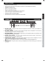
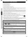
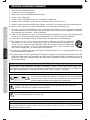
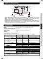
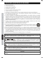
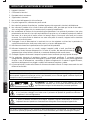
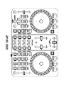
1. MIC INPUT JACK – This jack is used to connect a microphone to the device. Connect you microphone via
1/4-inch (6.3mm) jack.
2. MIC LEVEL CONTROL – This knob is used to adjust the output volume of microphone. Turn the knob in
clockwise direction to increase the microphone volume.
3. MIC TONE CONTROL – This knob is used to adjust the tone of microphone between Low and High. In the
center position, the tone control is middle.
4. MASTER LEVEL CONTROL – This knob is used to adjust the output volume of master. Turn the knob in
clockwise direction to increase the master volume.
5. MONITER LEVEL CONTROL – This knob is used to adjust the output volume of headphone. Turn the
knob in clockwise direction to increase the headphone volume.
Always be sure the MONITOR LEVEL is set to minimum before putting the headphones on.
6. MONITOR JACK - This jack is used to connect your headphones to the device allowing you to monitor the
cue source.
MAIN FEATURES
CONNECTION FRONT PANEL
1
23 4 5 6
2

ESPAÑOL
ITALIANO
NEDERLANDS
ENGLISH
FRANÇAIS
DEUTSCH
)
3. You may need to power on/ off the i-Mix Reload MKII when installing the driver.
4. Open the DJ software.
5. Start up the software to perform settings with the i-Mix Reload MKII.
The software may not recognize the i-Mix Reload MKII if it is connected to the computer after the
software has started.
6. Operations after the system recovering from power saving mode is not guaranteed.
Please power off and on again the unit when the system is recovered from power saving mode.
7. I-Mix Reload MKII can be used with many other DJ software products that have a MIDI LEARN function. The i-
Mix Reload MKII can control all software that has this function. i-Mix Reload MKII can be used to control
parameters of the software. Please visit http://www.djtechpro.com
for supported DJ software like Traktor Pro.
Some mapping files are also available there.
The MIDI LEARN setting for each software is different; please refer to each software's manual for further
instructions.
OPERATIONS
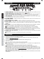
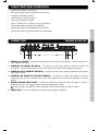
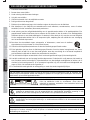
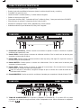
CONNECTION REAR PANEL
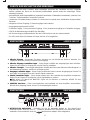
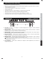
7. POWER CONNECTOR – Plug in power adapter here. DC adaptor can be used when the USB port cannot
provide enough power to the unit. Please use only a 6V DC adaptor.
8. POWER SWITCH (Adaptor / OFF/ USB power) – Set the switch to AC ADAPTOR when using external DC
adaptor (not included), set to USB BUSS POWER when using power provided from the computer via USB.
9. USB CONNECTOR – Used to connect a computer. It is recommended to use the USB Cable included.
Long or low quality USB cable may make the unit unstable.
10. C.F CURVE CONTROL – Adjusts the shape of the crossfader curve from a quick cut for scratching or to a
longer fade for mixing.
11. TOUCH SENSOR LEVEL CONTROL – Adjust the sensitivity of the jog wheel touch sensor.
12. OUTPUT JACKS – These jacks send a left and right analog output signal from the USB audio interface.
Use the supplied RCA cables to connect these outputs to a main stereo system, like an amplifier or active
speakers.
13. INPUT JACKS – You can connect playback devices to these input jacks, such as CD players, turntables,
SD players or USB players. These connections are for the inputs to the USB audio interface.
When connecting phono output turntables, be sure the corresponding switch is in the “PH” position.
When connecting line level output devices, be sure the corresponding switch is in the “LN” position
14. GND (GROUND TERMINAL) – Be sure to connect turntable ground leads to the available ground terminals.
This will reduce the humming and popping noises associated with magnetic phono cartridges.
15. CHANNEL LINE LEVEL SELECTOR - These switches are used to select the line levels type of the related
Phono/Line jacks.
Always be sure main power is shut off before switching the Line Level Selector.
1. Install the DJ software from the software CD included.
2. Install the ASIO driver for i-Mix Reload MKII from the Software CD “Drivers” folder. (ASIO Driver also
available on http://www.djtechpro.com
7
910
8
11
12 14
13
15
13
3

ESPAÑOL
ITALIANONEDERLANDS
ENGLISH
FRANÇAIS
DEUTSCH
4
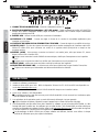
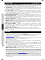
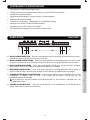
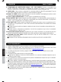
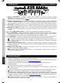
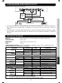
Block Diagram for the USB Audio Configuration
1. The audio interface of the unit is only an USB Audio Soundcard, while the faders and knobs controls are
for MIDI only. The unit cannot work as a mixer without the use of computer software.
2. Audio of Output 1 and Output 2 at the rear panel are the same, they are from USB Audio Output 1 plus the
Microphone signal.
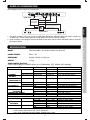
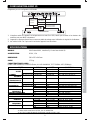
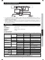
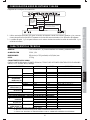
MODEL i-Mix Reload MKII , DJ Control Interface with Audio I/O
POWER SOURCE DC6V, 1.5A
DIMENSIONS 360(W) x 255(D) x 64.5(H) mm
WEIGHT 1.75 kg
AUDIO CHARACTERISTICS
(LOAD: LINE=100Kohm, PHONES=32ohm, ALL VR MAXIMUM, TEST SIGNAL: MP3,128Kbps)
ITEM TYPICAL LIMIT CONDITION
0.9V +/-0.5dB 0.9V +/-1dB 1KHz, 0dB (TCD-782 TRK.2) LINE OUTPUT 1&2
0.9V +/-1dB 0.9V +/-1.5dB MIC 1KHz, -36dB(LEVEL,TONE MAXIMUM)
OUTPUT LEVEL
PHONES 0.4V +/-0.5dB 0.4V +/-1dB 1KHz,-20dB (TCD-782 TRK.16)
CHANNEL
BALANCE
LINE OUTPUT 1&2 WITHIN 0.5dB WITHIN 1dB 1KHz, 0dB (TCD-782 TRK.2)
L/R CHANNEL
SEPARATION (*2)
LINE OUTPUT 1&2 80dB 76dB 1KHz, 0dB (TCD-782 TRK.9 & 11)
LINE OUTPUT 1&2 0.02% 0.05% 1KHz, 0dB (TCD-782 TRK.2) THD+N(*1)
PHONES 0.03% 0.06% 1KHz, 0dB (1V OUTPUT)
82dB 78dB 1KHz, 0dB (TCD-782 TRK.2 & 8) S/N RATIO(*2) LINE OUTPUT 1&2
65dB 60dB MIC 1KHz, -50dB(LEVEL,TONE MAXIMUM)
17Hz-16KHz+/-0.5dB 17Hz-16KHz+/-1dB (TCD-781 TRK.1,4 & 16) FREQUENCY
RESPONSE
LINE OUTPUT 1&2
20Hz-20KHz+/-1.5dB 20Hz-20KHz+/-3dB MIC 1KHz, -50dB(LEVEL,TONE MAXIMUM)
PHONES MAX. OUTPUT 1.5V 1.4V 1KHz, 0dB, THD=1%
MIC TONE -14dB +/-2dB -14dB +/-3dB 10KHz -50dB(TONE VR MAX TO MIN)
RECORD/PLAY SECTION (MASTER VR MAXIMUM)
0.8V +/-1dB 0.8V +/-1.5dB LINE IN 1KHz +6dBV(2V) y INPUT LEVEL LINE 1&2 OUTPUT
0.7V +/-1dB 0.7V +/-1.5dB PHONO IN 1KHz -30dBV
20Hz-20KHz +0/-1dB 20Hz-20KHz+0/-3dB LINE IN 1KHz +6dBV(2V) y FREQUENCY
RESPONSE
LINE 1&2 OUTPUT
20Hz-20KHz +1/-2dB 20Hz-20KHz+2/-3dB PHONO IN 1KHz -50dB (RIAA)
80dB 76dB LINE IN 1KHz +6dBV(2V) y S/N RATIO(*2) LINE1&2 OUTPUT
72dB 66dB PHONO IN 1KHz -30dBV
NOTES: *1: WITH 20KHz LOW PASS FILTER.
*2: WITH 20KHz LOW PASS FILTER, "IHF-A" WEIGHTED.
*3: ALL TEST CONDITION WITH EXTERNAL POWER SUPPLY UNIT.
SPECIFICATION
AUDIO I/O CONFIGURATION
2-in 2-out
USB Audio
Soundcard
Volume Control
Audio Out 1
Mic In
Audio Out 2
Audio In 2
Audio In 1
Audio Output to Rear Panel
FRONT PANEL
REAR PANEL
∑
USB

ESPAÑOL
ITALIANO
NEDERLANDS
ENGLISH
FRANÇAIS
DEUTSCH
1. Lisez les instructions suivantes.
2. Conservez ces instructions.
3. Respectez tous les avertissements.
4. Suivez toutes les instructions.
5. N’utilisez pas l’appareil près d’une source d’eau.
6. Nettoyez-le uniquement avec un chiffon doux et sec.
7. N’obstruez pas les ouvertures de ventilation. Installez l’appareil conformément aux instructions du fabricant.
8. N’installez pas l'appareil près de sources de chaleur telles qu’un radiateur, une bouche à air chaud, un
amplificateur ou tout autre appareil qui produit de la chaleur.
9. Ne contournez pas le dispositif de sécurité de la fiche polarisée ou avec mise à la terre. Toute fiche
polarisée dispose de deux lames dont une est plus grande que l’autre. Toute fiche avec mise à la terre
dispose de trois lames dont une pour la mise à la terre. La lame la plus large et la lame de mise à la terre
assurent votre sécurité. Si la fiche ne correspond pas à votre prise secteur, consultez un électricien pour
remplacer votre prise secteur obsolète.
10. Placez le cordon d’alimentation de manière à ne pas le piétiner ou l'écraser. Faites particulièrement
attention à la fiche et à l’endroit où le cordon sort de l’appareil.
11. Utilisez exclusivement des attaches/accessoires recommandé(e)s par le fabricant.
12. Ne placez pas ce produit sur une surface instable, cela pourrait causer des blessures
corporelles ou des dommages sérieux à l’appareil. Si vous utilisez un chariot, déplacez
l’appareil avec prudence afin d’éviter de le renverser et de blesser quelqu’un.
13. Débranchez l’appareil en cas d’orage ou de non-utilisation prolongée.
14. Confiez toutes les opérations d'entretien à un technicien qualifié. Une réparation est nécessaire lorsque l’appareil
a été endommagé de quelque manière que ce soit : fiche ou câble d’alimentation abîmé(e), introduction de
liquides ou d’objets dans l’appareil, exposition à la pluie ou à l’humidité, dysfonctionnement, chute.
15. La fiche permet de débrancher l’appareil et doit rester facilement accessible.
AVERTISSEMENT
Pour réduire le risque d'incendie ou de choc électrique, n’exposez pas cet appareil à la pluie ou à l'humidité.
Ne placez aucun récipient rempli de liquide, tel qu’un vase, à proximité de celui-ci.
ATTENTION : Ne démontez pas l’appareil afin de prévenir tout
risque de choc électrique. Aucune pièce interne ne peut être
réparée par l’utilisateur. Confiez toutes les opérations d'entretien
à un technicien qualifié.
Le symbole de l'éclair terminé par une flèche situé à l'intérieur d'un triangle équilatéral avertit
l'utilisateur de la présence de tension dangereuse non isolée dans l'appareil, dont l’amplitude peut
constituer un risque de choc électrique
.
Le symbole du point d’exclamation dans un triangle équilatéral vise à avertir l’utilisateur de la
présence, dans la documentation accompagnant cet appareil, d’importantes instructions de
fonctionnement et d’entretien.
ATTENTION
Pour prévenir tout risque de choc électrique, veillez à ce que les bornes de la fiche d’alimentation soient
insérées complètement, de manière à ne pas être exposées.
INFORMATION DE SECURITE IMPORTANTE
DO NOT OPEN
RISK OF ELECTRIC SHOCK
5

ESPAÑOL
ITALIANONEDERLANDS
ENGLISH
FRANÇAIS
DEUTSCH
y Contrôleur USB MIDI Plug and Play
y Roue Jog sensitive pour Pitch Bending et Scratching.
y Courbe du crossfader ajustable
y Interface Audio 2 entrées 2 sorties
y Sortie Line Maximum 0.9V RMS
y 1 MIC, 2 Entrées Line, 2 Sorties Line et 1 Sortie Phone
y LED d’alimentation et indication d’activité MIDI
y Alimenté par USB ou par adaptateur secteur externe
y Driver Audio ASIO inclus pour Windows XP/ Vista et Mac
1. ENTRÉE JACK MICRO – Cette entrée est utilisée pour connecter un microphone. Connecter votre micro
via un câble jack 6.35mm.
2. CONTROLE DU NIVEAU DU MICRO – Ce bouton est utilisé pour ajuster la sortie du volume du
microphone. Tourner le bouton dans le sens d’une aiguille d’une montre pour augmenter le volume.
3. CONTROLE DE LA TONALITE DU MICRO – Ce bouton est utilisé pour ajuster la tonalité du microphone
entre grave et aigue.
4. CONTROLE DU NIVEAU DU VOLUME PRINCIPAL – Ce bouton est utilisé pour ajuster la sortie du
volume principal. Tourner le bouton dans le sens d’une aiguille d’une montre pour augmenter le volume
master.
5. BOUTON VOLUME PRE ECOUTE – Ce bouton est utilisé pour ajuster le volume du casque. Tourner le
bouton dans le sens d’une aiguille d’une montre pour augmenter le volume.
Toujours vérifier que MONITOR LEVEL est régler sur le minimum avant de mettre le casque.
6. PRE ECOUTE – Ce jack est utilisé pour connecter votre casque sur l’appareil.
CARACTERISTIQUES PRINCIPALES
CONNECTION PANNEAU DU DESSUS
1
23 4 5 6
6

ESPAÑOL
ITALIANO
NEDERLANDS
ENGLISH
FRANÇAIS
DEUTSCH
7. CONNECTEUR D’ALIMENTATION – Brancher l’adaptateur secteur ici.
8. BOUTON D’ALIMENTATION (Adaptateur / OFF/ USB power) – Régler le bouton en position AC ADAPTOR
lorsque vous utilisez l’adaptateur secteur, régler le bouton en position USB POWER lorsque l’alimentation
provient de l’ordinateur via USB.
9. ENTRÉE USB – Utilisez l’entrée USB pour connecter à l’ordinateur.
10. CONTROLE C.F CURVE – Permet de régler la forme de la courbe du crossfader rapidement, pour
scratcher ou pour mixer.
11. CONTROLE DU NIVEAU DE LA SENSIBILITE AU TOUCHER – Permet de régler la sensibilité du toucher.
12. SORTIE JACKS – Envoie des signaux de sorties gauches et droites analogues de l’interface audio USB.
Utiliser les câbles RCA pour connecter ces sorties à un système stéréo principal tel un ampli ou des
enceintes actives.
13. ENTREE JACKS – Vous pouvez connecter un lecteur à cet entrée jacks, tells que lecteur CD, tourne
disque, lecteurs SD ou lecteur USB.
Lorsque vous connectez la sortie PHONO du tourne disque, vérifier que l’interrupteur est sur la position
“PH”.
Lorsque vous connectez la sortie line, vérifiez que l’interrupteur est sur la position “LN”
14. MASSE (GND) – vérifiez que vous avez bien connecté les masses des l’appareil.
15. SELECTEUR DE CANAL LINE – ce sélecteur est utilisé pour sélectionner le type d’entrée Phono/Line.
Toujours vous assurez que l’alimentation est éteinte avant d’utiliser le sélecteur.
1. Installer le software normalement.
2. Installer le driver ASIO pour i-Mix MKII du répertoire “Drivers” du CD. (le Driver ASIO est disponible sur
le site http://www.djtechpro.com
)
3. Vous avez besoin d’allumer/d’éteindre le i-Mix Reload MKII lorsque vous installer le driver.
4. Ouvrir le DJ software. i-Mix Reload MKII.
Le software pourrait ne pas être reconnu par le i-Mix Reload MKII s’il est connecté sur l’ordinateur après
que le software ait démarré.
5. Les opérations de récupération après un mode d’économie d’énergie n’est pas garantie.
Veuillez éteindre et rallumer l’appareil lorsque l’appareil est en mode d’économie d’énergie.
6. I-Mix Reload MKII peut être utilise avec pleins d’autres DJ software qui ont la fonction MIDI LEARN. Le i-Mix
Reload MKII peut contrôler tous les softwares qui ont cette fonction. i-Mix Reload MKII peut être utilisé pour
contrôler les paramètres du software. Veuillez visiter le site http://www.djtechpro.com
afin de soutenir les logiciels
DJ tels que Traktor Pro. D’autres fichiers sont également disponibles sur le site.
Le paramétrage du MIDI LEARN pour chaque software est différent; Veuillez vous référer à chaque
manuel de l’utilisateur pour plus amples informations.
OPERATIONS
CONNECTION PANNEAU ARRIERE
7
910
8
11
12 14
13
15
13
7

ESPAÑOL
ITALIANONEDERLANDS
ENGLISH
FRANÇAIS
DEUTSCH
8
Diagramme pour la configuration USB Audio
1. L’interface audio de l’appareil est uniquement une carte Son USB, tandis que le fader et les boutons de
contrôles sont pour MIDI uniquement.
2. L’appareil ne peut pas fonctionner comme une table de mixage sans l’utilisation du logiciel de l’ordinateur.
3. Les sorties Audio 1 et 2 qui sont à l’arrière de l’appareil sont les même.
MODELE i-Mix Reload MKII , Interface DJ Control avec Audio I/O
ALIMENTATION DC6V, 1.5A
DIMENSIONS 360 x 255 x 64.5mm
POIDS 1.75 kg
CARACTERISTIQUES AUDIO
(LOAD: LINE=100Kohm, PHONES=32ohm, ALL VR MAXIMUM, TEST SIGNAL: MP3,128Kbps)
OBJET TYPICAL LIMITE CONDITION
0.9V +/-0.5dB 0.9V +/-1dB 1KHz, 0dB (TCD-782 TRK.2) LINE OUTPUT 1&2
0.9V +/-1dB 0.9V +/-1.5dB MIC 1KHz, -36dB(LEVEL,TONE MAXIMUM)
NIVEAU DE
SORTIE
PHONES 0.4V +/-0.5dB 0.4V +/-1dB 1KHz,-20dB (TCD-782 TRK.16)
CHANNEL
BALANCE
LINE OUTPUT 1&2 WITHIN 0.5dB WITHIN 1dB 1KHz, 0dB (TCD-782 TRK.2)
L/R CHANNEL
SEPARATION (*2)
LINE OUTPUT 1&2 80dB 76dB 1KHz, 0dB (TCD-782 TRK.9 & 11)
LINE OUTPUT 1&2 0.02% 0.05% 1KHz, 0dB (TCD-782 TRK.2) THD+N(*1)
PHONES 0.03% 0.06% 1KHz, 0dB (1V OUTPUT)
82dB 78dB 1KHz, 0dB (TCD-782 TRK.2 & 8) S/N RATIO(*2) LINE OUTPUT 1&2
65dB 60dB MIC 1KHz, -50dB(LEVEL,TONE MAXIMUM)
17Hz-16KHz+/-0.5dB 17Hz-16KHz+/-1dB (TCD-781 TRK.1,4 & 16) REPONSE EN
FREQUENCE
LINE OUTPUT 1&2
20Hz-20KHz+/-1.5dB 20Hz-20KHz+/-3dB MIC 1KHz, -50dB(LEVEL,TONE MAXIMUM)
SORTIES PHONES MAX. 1.5V 1.4V 1KHz, 0dB, THD=1%
TONALITE MIC -14dB +/-2dB -14dB +/-3dB 10KHz -50dB(TONE VR MAX TO MIN)
SECTION ENREGISTREMENT/LECTURE (MASTER VR MAXIMUM)
0.8V +/-1dB 0.8V +/-1.5dB LINE IN 1KHz +6dBV(2V) y NIVEAU
D’ENTREE
LINE 1&2 OUTPUT
0.7V +/-1dB 0.7V +/-1.5dB PHONO IN 1KHz -30dBV
20Hz-20KHz +0/-1dB 20Hz-20KHz+0/-3dB LINE IN 1KHz +6dBV(2V) y REPONSE EN
FREQUENCE
LINE 1&2 OUTPUT
20Hz-20KHz +1/-2dB 20Hz-20KHz+2/-3dB PHONO IN 1KHz -50dB (RIAA)
80dB 76dB LINE IN 1KHz +6dBV(2V) y S/N RATIO(*2) LINE1&2 OUTPUT
72dB 66dB PHONO IN 1KHz -30dBV
REMARQUES: *1: WITH 20KHz LOW PASS FILTER.
*2: WITH 20KHz LOW PASS FILTER, "IHF-A" WEIGHTED.
*3: ALL TEST CONDITION WITH EXTERNAL POWER SUPPLY UNIT.
SPECIFICATIONS
CONFIGURATION AUDIO I/O
Contrôle du Volume
Sortie Audio 1
Entrée Mic
Sortie Audio 2
Entrée Audio 2
Entrée Audio 1
Sortie Audio à l'arrière
PANNEAU AVANT
PANNEAU ARRIERE
∑
USB
Carte son USB
2-entrées
2-sorties

NEDERLANDS
ESPAÑOL
ITALIANO
ENGLISH
FRANÇAIS
DEUTSCH
1. Lesen Sie diese Betriebsanleitung.
2. Verwahren Sie diese Anleitung auf.
3. Beachten Sie alle hier aufgeführten Warnhinweise.
4. Folgen Sie den Anleitungen.
5. Setzen Sie das Gerät weder Regen noch sonstiger Feuchtigkeit aus
6. Reinigen Sie die Oberfläche des Gerätes nur mit einem weichen, trockenen Tuch.
7. Achten Sie auf ausreichende Belüftung des Gerätes und stellen Sie es entsprechend den Anweisungen auf.
8. Stellen Sie das Gerät nicht an direkte Wärmequellen (z.B. Heizungen / Verstärkern) auf.
9. Verändern Sie nicht die Masseleitung. Auch das Betreiben des Gerätes an einer ungeerdeten Steckdose
kann lebensgefährlich sein. Stellen Sie daher sicher, dass Sie das Gerät an einer fachgerecht installierten
Netz-Steckdose von 100-240 V, 50 -60 Hz betreiben.
10. Legen Sie das Netzkabel so, dass es frei liegt und nirgends eingeklemmt ist oder leicht herausgerissen
werden kann. Dort wo es aus dem Gerät herauskommt, soll es nicht unter Zugspannung stehen.
11. Verwenden Sie ausschließlich original Gerate Hersteller Zusatzprodukte und Erweiterungen.
12. Das Gerät sollte zu Ihrer Sicherheit nur auf Wagen, Ständern, oder Tischen aufbewahrt
und betrieben werden die für professionelle Audio- und
Musikinstrumente geeignet sind.
Achten Sie immer darauf, dass die jeweiligen Geräte sicher installiert
sind, um Schäden und
Verletzungen zu vermeiden. Wenn Sie einen Rollwagen benutzen, achten Sie
darauf, dass
dieser nicht umkippen kann, um Verletzungen auszuschließen.
13. Im Falle eines Gewitters oder auch bei längerer Nichtinbetriebnahme ist es ratsam den Netzstecker aus
der Wandsteckdose zu entfernen.
14. Die Wartung sollte nur durch qualifiziertes Fachpersonal erfolgen. Eine Wartung wird notwendig, wenn
das
Gerät beschädigt wurde, das Stromkabel oder der Stecker, Gegenstände oder Flüssigkeiten in
das Gerät
gelangt sind. Das Gerät heruntergefallen, dem Regen oder Feuchtigkeit ausgesetzt war und deshalb nicht
mehr
normal arbeitet.
WARNUNG
Um das Risiko eines elektrischen Schlages zu minimieren, setzen Sie das Gerät niemals Regen oder
Feuchtigkeit aus. Meiden Sie auch den Kontakt mit tropfenden, spritzenden Flüssigkeiten und stellen Sie
keine mit Flüssigkeit befüllten Gegenstände auf das Gerät. (Gläser, Flaschen, Vasen etc.)
ACHTUNG: Um das Risiko eine elektrischen Schlages zu minimieren, entfernen
Sie niemals das Gehäuse des Gerätes. Es befinden sich keine vom Anwender
auszutauschenden Teile im Gerät. Eine Reparatur oder die Überprüfung des
Gerätes erfolgt ausschließlich durch qualifiziertes Fachpersonal.
Dieses Symbol warnt den Benutzer vor nicht isolierter Spannung innerhalb des Gerätes, die
gefährliche elektrische Schläge verursachen können.
Dieses Symbol weist den Benutzer darauf hin, dass es wichtige Funktions- und Wartungshinweise
in der Produkt-Begleitenden Anleitung gibt.
ACHTUNG
Um das Risiko eines elektrischen Schlages zu minimieren, sollten Sie bei der Verwendung von Mehrfach-
und Verteilersteckdosen darauf achten, dass diese korrekt geerdet sind und der Geräte-Netzstecker
vollständig eingesteckt wurde.
WICHTIGE SICHERHEITSHINWEISE
DO NOT OPEN
RISK OF ELECTRIC SHOCK
9

ESPAÑOL
ITALIANONEDERLANDS
ENGLISH
FRANÇAIS
DEUTSCH
y Plug-and-Play USB MIDI Controller. Beim erstmaligen Anschluss des Controllers an einen Computer
werden nachdem das Great von der Betriebs-Systemsoftware erkannt wurde alle notwendigen Treiber
automatisch geladen.
y Hochauflösende, berührungsempfindliche Jogwheels (Drehscheiben / Plattenteller) um authentisch „scratchen“ und
Tonhöhen- Tempokorrekturen vornehmen zu können.
y Justierbares Crossfader-blenden verhalten. Sie können den Crossfader Ihren individuellen mixing Vorlieben
anpassen.
y Integriertes 2 Stereo Eingänge, 2 Stereo Ausgänge Audio Interface
y Ausgangsleistung Maximal 0.9V RMS
y 1 Mikrofon Eingang, 2 Line (Instrument) Eingänge, 2 Line (Instrument) Ausgänge und 1 Kopfhörer Ausgang.
y LED für die Betriebsanzeige und MIDI-Bus Aktivitäten.
y Die Stromversorgung erfolgt wahlweise über den USB-Anschluss oder ein externes Netzteil.
y Ein ASIO Audio Driver für Windows XP/ Vista und Mac OS ist mitgeliefert.
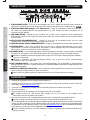
1. Mikrofon Eingang – Verwenden Sie diesen Anschluss um ein Mikrofon am Gerät zu betreiben. Der
Eingang ist als 4-inch (6.3mm) Klinken-Buchse ausgelegt.
2. Mikrofon Eingangs Lautstärke Regler – Dieser Regler verstärkt das Ausgangssignal Ihres Mikrofons.
Drehen Sie den Regler im Uhrzeigersinn um das Signal zu verstärken.
3. Mikrofon Tonregler – Dieser Regler dämpft oder verstärkt die Höhen oder Bässe des Mikrofonsignals. In
der Mittelstellung betrieben, verhält sich der Regler neutral.
4. Ausgangs Lautstärke Regler – Dieser Regler verstärkt das Stereo-Summen Ausgangssignal. Drehen Sie
den Regler im Uhrzeigersinn um das Summen-Signal anzupassen.
5. Monitor Lautstärke Regler – Dieser Regler erlaubt Ihnen die Lautstärke des Kopfhörers anzupassen.
Drehen Sie den Regler im Uhrzeigersinn um die Signalstärke zu justieren.
Bitter achten Sie darauf das MONITOR Signal auf ein Minimum zu reduzieren BEVOR Sie den
Kopfhörer verwenden.
6. MONITOR Anschluss – Diese Anschlussbuchse wird verwendet um einen Kopfhörer anzuschließen.
Mit Hilfe diese Ausgangs Kanals, können Sie Ihr Monitorsignal vorhören.
7. NETZSTECKER ANSCHLUSS – Schließen Sie hier ein passendes Netzteil an. Das Netzteil kann
verwendet werden wenn die vom PC - Notebook gelieferte USB Stromstärke nicht ausreichen sollten.
Verwenden Sie ausschließlich einen 6V Wechselstrom Adapter. (Nicht mitgeliefert)
GERÄTE EIGENSCHAFTEN UND MERKMALE
ANSCHLÜSSE
V
ORDER ANSICHT
ANSCHLÜSSE RÜCK ANSICHT
1
23 4 5 6
7
910
8
11
12 14
13
15
13
10

NEDERLANDS
ESPAÑOL
ITALIANO
ENGLISH
FRANÇAIS
DEUTSCH
8. NETZ SCHALTER (Adaptor / OFF/ USB power) – Stellen Sie den Schalter auf „AC ADAPTOR“ wenn Sie ein
externes Netzteil verwenden (Nicht mitgeliefert), Stellung auf USB POWER wenn Sie das Gerät mit dem
Anschluss Strom betreiben wollen, welcher von Ihrem Laptop- / Desktop Computer geliefert wird.
9. USB ANSCHLUSS – Verwenden Sie diese Buchse zum Anschluss des USB Kabels. Wir empfehlen das
mitgelieferte USB Kabel zu verwenden. Besonders lange oder qualitativ minderwertige Kabel können zu
einer Beeinträchtigung des Betriebes führen.
10. C.F CURVE CONTROL – Justieren Sie mithilfe diese Reglers das „Blenden-Verhalten“ des Crossfaders.
Sie haben die Möglichkeit von einer scharfkantigen- bis zu einem weichen Überblendungs-Verhalten zu
variieren. Steilere Regelkurven eignen sich besonders zum „Scratchen“, hingegen werden weichere
Kurven-Verläufe bei längeren Kreuz-Blenden, (crossfades) verwendet.
11. TOUCH SENSOR LEVEL CONTROL – regulieren Sie hier die Berührungsempfindlichkeit des Jogwheels.
12. AUSGANGS ANSCHLUESSE – Diese Buchsen liefern ein getrenntes Stereosignal für den rechten und
linken Kanal des USB Mixers. Verwenden Sie die mitgelieferten Audio Kabel um das Signal z.B. einem
Verstärker oder aktiven Lautsprecher zuzuführen.
13. EINGANGS ANSCHLUESSE – Sie können hier externe Zuspieler (z.B. Plattenspieler, CD-Player, MP-3
Player, etc.) anschließen. Über diese Eingangs Anschlüsse werden die Audiosignale dem Gerät zugeführt.
Stellen Sie sicher, dass bei Verwendung eines Plattenspielers der Eingangs Empfindlichkeits-Schalter auf
Position „PH“ steht.
Stellen Sie den Eingangs Empfindlichkeits-Schalter auf Position „LN“ bei Verwendung von „line level
Geräten“, wie z.B. CD-Playern, MP3-Playern.
14. GND (GROUND TERMINAL) – Verbinden Sie das Erdungskabel eines Plattenspielers mit dieser
Schraubverbindung. Eine korrekte Erdung des Plattenspielers verhindert Brumm- und andere
möglicherweise auftretende Stör-Signale, verursacht durch die magnetischen Eigenschaften der
Plattennadel des Abtastkopfes.
15. CHANNEL LINE LEVEL SELECTOR – Wahlen Sie hier zwischen „Line“ und „Phone“ Eingang aus.
Bitte stellen Sie sicher, dass das Gerät vom Netz getrennt und ausgeschaltet ist BEVOR Sie zwischen
Line und Phono wählen.
1. Installieren Sie die mitgelieferte DJ Software von der beiliegen CD.
2. Installieren Sie nun den ASIO Treiber für das Gerat i-Mix Reload MK II. Sie finden den Treiber auf der CD
im Ordner „Drivers“. Selbstverständlich können Sie die Treiber auch von unserer Website unter:
http://www.djtechpro.com
herunterladen.
3. Bitte schalten Sie das Gerät, falls schon angeschlossen, nach der Installation kurz ein und aus, damit die
Systemsoftware den i-Mix Reload MK II. vollständig installieren kann.
4. Starten Sie nun die DJ-Software.
5. Folgen Sie den Installationsanweisungen der DJ-Software und konfigurieren Sie das Programm, damit es
reibungslos mit dem i-Mix Reload MK II arbeitet.
Eventuell erkennt die Software den i-Mix Reload MK II nicht wenn Sie das Gerät NACH dem Start der
DJ-Software angeschlossen haben. Bitte schließen Sie ggf. die Anwendung und wiederholen den Start-
Vorgang MIT korrekt angeschlossenem i-Mix Reload MKII.
6. Eine einwandfreie Funktionalität nach einem Stromausfall / Stromsparmodus und dem daraus
resultierenden Neustart / Aufwachen des Systems kann nicht gewährleistet werden.
Bitte überprüfen Sie alle Einstellungen und trennen und verbinden Sie den I-Mix Reload MKII. ggf.
nochmals mit dem Computer.
7. Der I-Mix Reload MKII kann mit einer Vielzahl von DJ-Software Anwendungen betrieben werden, die über
Standard MIDI Controller Befehle gesteuert werden können und die sogn. „MIDI Learn“ Funktionalität bieten.
Sollte Ihre favorisiere DJ-Software eine „MIDI Learn“ Funktionalität aufweisen, lässt sich der i-Mix Reload MKII als
vielseitiger MIDI Controller verwenden um zahlreiche Software Parameter zu steuern und kontrollieren zu können.
Bitte besuchen Sie unsere Website http://www.djtechpro.com
um mehr Informationen über die von uns
unterstützten Software Produkte zu erhalten. Sie finden dort auch sogn. Mappings (fertige Konfigurationsdateien)
für DJ-Software wie z.B TRAKTOR PRO und anderen gängigen Produkten.
Die MIDI Learn Parameter variieren von Hersteller zu Hersteller. Für ausführliche Informationen zum
Thema MIDI–Parameter, Steuerungsbefehle und Mappings wenden Sie sich bitte direkt an die jeweiligen
Software Hersteller.
BETRIEB
ANSCHLÜSSE RÜCK ANSICHT
11

ESPAÑOL
ITALIANONEDERLANDS
ENGLISH
FRANÇAIS
DEUTSCH
12
Block Diagram der USB Audio Konfiguration
1. Das Soundkarten Modul im Gerät ist ein USB Audio-Interface. Die Flachbahnregler (Fader) sowie alle
weiteren Tasten dienen nur der MIDI Kontrolle. Das Gerät fungiert nicht als AUDIO–Mixer. Nur in
Verbindung mit einer Audio / DJ Software können Audiosignale wiedergegeben werden.
2. Audio Ausgang 1 und Audio Ausgang 2 sind identisch. Sie erhalten hier immer das Summensignal des USB
Audio-Interfaces, inclusive des Mikrofonsignals. Ihr Monitor Mix wird ausschließlich über den Kopfhörer
Anschluss der Vorderseite des i-Mix Reload MKII ausgegeben.
MODEL
i-Mix Reload MKII , DJ Control Interface with Audio I/O
NETZTEIL-EINGANGSPANNUNG
DC6V, 1.5A
ABMESSUNGEN
360(Breite) x 255(Tiefe) x 64.5(Höhe) mm
GEWICHT
1.75 kg
AUDIO MERKMALE / EIGENSCHAFTEN
(LOAD: LINE=100Kohm, PHONES=32ohm, ALL VR MAXIMUM, TEST SIGNAL: MP3,128Kbps)
ITEM TYPICAL LIMIT CONDITION
0.9V +/-0.5dB 0.9V +/-1dB 1KHz, 0dB (TCD-782 TRK.2) LINE OUTPUT 1&2
0.9V +/-1dB 0.9V +/-1.5dB MIC 1KHz, -36dB(LEVEL,TONE MAXIMUM)
OUTPUT LEVEL
PHONES 0.4V +/-0.5dB 0.4V +/-1dB 1KHz,-20dB (TCD-782 TRK.16)
CHANNEL
BALANCE
LINE OUTPUT 1&2 WITHIN 0.5dB WITHIN 1dB 1KHz, 0dB (TCD-782 TRK.2)
L/R CHANNEL
SEPARATION (*2)
LINE OUTPUT 1&2 80dB 76dB 1KHz, 0dB (TCD-782 TRK.9 & 11)
LINE OUTPUT 1&2 0.02% 0.05% 1KHz, 0dB (TCD-782 TRK.2) THD+N(*1)
PHONES 0.03% 0.06% 1KHz, 0dB (1V OUTPUT)
82dB 78dB 1KHz, 0dB (TCD-782 TRK.2 & 8) S/N RATIO(*2) LINE OUTPUT 1&2
65dB 60dB MIC 1KHz, -50dB(LEVEL,TONE MAXIMUM)
17Hz-16KHz+/-0.5dB 17Hz-16KHz+/-1dB (TCD-781 TRK.1,4 & 16) FREQUENCY
RESPONSE
LINE OUTPUT 1&2
20Hz-20KHz+/-1.5dB 20Hz-20KHz+/-3dB MIC 1KHz, -50dB(LEVEL,TONE MAXIMUM)
PHONES MAX. OUTPUT 1.5V 1.4V 1KHz, 0dB, THD=1%
MIC TONE -14dB +/-2dB -14dB +/-3dB 10KHz -50dB(TONE VR MAX TO MIN)
RECORD/PLAY SECTION (MASTER VR MAXIMUM)
0.8V +/-1dB 0.8V +/-1.5dB LINE IN 1KHz +6dBV(2V) y INPUT LEVEL LINE 1&2 OUTPUT
0.7V +/-1dB 0.7V +/-1.5dB PHONO IN 1KHz -30dBV
20Hz-20KHz +0/-1dB 20Hz-20KHz+0/-3dB LINE IN 1KHz +6dBV(2V) y FREQUENCY
RESPONSE
LINE 1&2 OUTPUT
20Hz-20KHz +1/-2dB 20Hz-20KHz+2/-3dB PHONO IN 1KHz -50dB (RIAA)
80dB 76dB LINE IN 1KHz +6dBV(2V) y S/N RATIO(*2) LINE1&2 OUTPUT
72dB 66dB PHONO IN 1KHz -30dBV
NOTES: *1: WITH 20KHz LOW PASS FILTER.
*2: WITH 20KHz LOW PASS FILTER, "IHF-A" WEIGHTED.
*3: ALL TEST CONDITION WITH EXTERNAL POWER SUPPLY UNIT.
SPECIFICATION
AUDIO I/O KONFIGUARTION
Lautstärke Regler
Mikrofon Eingang
Audio Ausgang 2
Audio Eingang 2
Audio Ausgang zur Rückseite
VORDERSEITEL
RÜCKSEITE
∑
USB
Stereo Ein/
Stereo Ausgang
USB Soundkarte
Audio Eingang 1
Audio Ausgang 1

ESPAÑOL
ITALIANO
NEDERLANDS
ENGLISH
FRANÇAIS
DEUTSCH
1. Lees deze voorschriften.
2. Bewaar deze voorschriften.
3. Houd rekening met alle waarschuwingen.
4. Volg alle voorschriften.
5. Gebruik het toestel niet in de nabijheid van water.
6. Reinig enkel met een droge doek.
7. Blokkeer de ventilatie-openingen niet. Installeer volgens de instructies van de fabrikant.
8. Niet installeren in de nabijheid van warmtebronnen zoals radiatoren, warmteroosters, ovens of andere
toestellen (inclusief versterkers) die warmte produceren.
9. Houd rekening met de veiligheidsdoelstelling van de gepolariseerde stekker of de aardingsstekker. Een
gepolariseerde stekker heeft twee pinnen waarvan de ene breder is dan de andere. Een aardingsstekker
heeft twee pinnen en een derde aardingspin. De brede pin of de derde pin zijn voorzien voor uw veiligheid.
Als de meegeleverde stekker niet in uw stopcontact past, raadpleeg dan een elektricien voor vervanging
van het verouderde stopcontact.
10. Bescherm de stroomkabels tegen vertrappelen of belemmeren, vooral aan de stekkers,
stopcontacten en het punt waar ze uit het toestel komen.
11. Gebruik enkel hulpstukken/toebehoren die door de fabrikant gespecificeerd worden.
12. Enkel gebruiken met een door de fabrikant gespecificeerde of met het toestel meegeleverde kar, steun,
drievoet, plank of tafel. Als er een kar wordt gebruikt, wees dan voorzichtig als u het toestel verplaatst in
een kar/toestel-combinatie om letsels door omkantelen te vermijden.
13. Trek het toestel uit tijdens onweersbuien of als het toestel gedurende lange tijd niet wordt gebruikt.
14. Laat alle onderhoud over aan bevoegd onderhoudspersoneel. Onderhoud is nodig wanneer het toestel op
een of andere manier beschadigd is, bijvoorbeeld door een beschadigde voedingskabel of stekker, als er
vloeistof op het toestel gemorst is of er voorwerpen ingevallen zijn, als het toestel werd blootgesteld aan
regen of vocht, niet normaal werkt of gevallen is.
15. De hoofdstekker wordt gebruikt als ontkoppeling en moet dus steeds toegankelijk blijven.
WAARSCHUWING
Stel het toestel niet bloot aan regen of vocht om het risico op brand of elektrische schok te vermijden. Het
toestel mag niet blootgesteld worden aan druppels of spatten en er mogen geen voorwerpen met vloeistof,
zoals vazen, op het toestel geplaatst worden.
WAARSCHUWING: Geen beschermingen verwijderen om het
risico op elektrische schok te verminderen. Geen door de
gebruiker te repareren onderdelen. Laat onderhoud enkel over
aan bevoegd personeel.
Het symbool van een driehoek met een bliksemschicht die eindigt op een pijl is bedoeld om de
gebruiker te waarschuwen voor de aanwezigheid van ongeïsoleerde “gevaarlijke spanning” in het
product die van zulke omvang kan zijn dat het een risico op elektrische schok vormt.
De gelijkzijdige driehoek met het uitroepteken is bedoeld om de gebruiker te waarschuwen voor de
aanwezigheid van belangrijke bedienings- en onderhoudsvoorschriften in de documentatie die bij dit
toestel hoort.
WAARSCHUWING
Om elektrische schok te vermijden, de gepolariseerde stekker niet gebruiken met een verlengkabel,
stopcontact of andere ontvanger, tenzij de pinnen er helemaal kunnen ingestoken worden zodat er geen
blootstelling van de pinnen is.
BELANGRIJKE VEILIGHEIDSVOORSCHRIFTEN
DO NOT OPEN
RISK OF ELECTRIC SHOCK
13

ESPAÑOL
ITALIANONEDERLANDS
ENGLISH
FRANÇAIS
DEUTSCH
y Plug-and-play USB MIDI-besturingseenheid
y Tactiele jog wheels met hogeresolutiepulssensors voor pitch bending en scratchen
y Verstelbare crossfader-kromme
y Ingebouwde geluidsinterface 2 stereo-ingangen, 2 stereo-uitgangen
y Maximaal 0,9 V RMS-lijnuitgang
y 1 microfoon, 2 lijningangen, 2 lijnuitgangen en 1 hoofdtelefoonuitgang.
y Stroom-led voor stroom- en MIDI-activiteitenindicatie
y Aangedreven door USB of externe DC-adapter
y ASIO-geluidsdriver inbegrepen voor Windows XP/Vista en Mac
1. MICROFOONINGANGSJACK – Deze jack wordt gebruikt om een microfoon op het toestel aan te sluiten.
Sluit uw microfoon via de jack van 6,3 mm (1/4 inch) aan.
2. MICROFOONVOLUMEREGELING – Deze knop wordt gebruikt om het uitgangsvolume van de microfoon
te regelen. Draai de knop in de richting van de wijzers van de klok om het microfoonvolume te verhogen.
3. MICROFOONTOONREGELING – Deze knop wordt gebruikt om de toon van de microfoon te regelen
tussen laag en hoog. In de middenstand staat de toonregeling in het midden.
4. MASTERVOLUMEREGELING – Deze knop wordt gebruikt om het uitgangsvolume van de master te
regelen. Draai de knop in de richting van de wijzers van de klok om het mastervolume te verhogen.
5. VOORBELUISTERINGSVOLUMEREGELING – Deze knop wordt gebruikt om het uitgangsvolume van de
hoofdtelefoon te regelen. Draai de knop in de richting van de wijzers van de klok om het
hoofdtelefoonvolume te verhogen.
Zorg er altijd voor dat het VOORBELUISTERINGSVOLUME op het minimum is ingesteld voor u de
hoofdtelefoon opzet.
6. VOORBELUISTERINGSJACK – Deze jack wordt gebruikt om uw hoofdtelefoon op het toestel aan te
sluiten, zodat u de cue source kunt beluisteren.
V
OORNAAMSTE EIGENSCHAPPEN
AANSLUITING VOORPANEEL
1
23 4 5 6
14

ESPAÑOL
ITALIANO
NEDERLANDS
ENGLISH
FRANÇAIS
DEUTSCH
7. STROOMAANSLUITING – Sluit hier uw stroomadapter aan. De DC-adapter kan gebruikt worden wanneer de
USB-poort onvoldoende stroom aan de eenheid levert. Gebruik uitsluitend een DC-adapter van 6 V.
8. STROOMSCHAKELAAR (adapter / UIT / USB-stroom) – Plaats de schakelaar op ADAPTOR wanneer u
een externe DC-adapter gebruikt (niet meegeleverd) of op USB POWER wanneer u de stroom van de
computer via USB gebruikt.
9. USB-AANSLUITING – Gebruikt om een computer aan te sluiten. Het is raadzaam om de meegeleverde
USB-kabel te gebruiken. Een lange USB-kabel of een kabel van slechte kwaliteit zou de eenheid onstabiel
kunnen maken.
10. CROSSFADER-KROMMEREGELING – Verstelt de vorm van de crossfader-kromme van een snelle
overgang om te scratchen naar een lange overgang om te mixen.
11. NIVEAUREGELING VAN DE AANRAAKSENSOR – Regelt de gevoeligheid van de jog wheel-aanraaksensor.
12. UITGANGJACKS – Deze jacks versturen een links en rechts analoog uitgangssignaal van de USB-
geluidsinterface. Gebruik de meegeleverde RCA-kabels om deze uitgangen op een hoofdstereosysteem
aan te sluiten, zoals een versterker of actieve luidsprekers.
13. INGANGSJACKS – U kunt afspeelapparatuur op deze ingangsjacks aansluiten, zoals cd-spelers, draaitafels,
SD-spelers of USB-spelers. Deze aansluitingen dienen voor de ingangen naar de USB-geluidsinterface.
Wanneer u draaitafels met phono-uitgang aansluit, zorg er dan voor dat de overeenkomstige schakelaar
op de “PH”-stand staat.
Wanneer u apparatuur met lijnniveau-uitgang aansluit, zorg er dan voor dat de overeenkomstige
schakelaar op de “LN”-stand staat.
14. GND (AARDINGSKLEM) – Zorg ervoor dat u de aardingsleidingen van de draaitafel op de beschikbare
aardingsklemmen aansluit. Dit zal de brommende en ploffende geluiden verminderen die gepaard gaan met
magneetbandcassettes.
15. KANAALLIJNNIVEAUSCHAKELAAR – Deze schakelaars worden gebruikt om het type van de lijnniveaus
van de overeenkomstige Phono/Line-jacks te selecteren.
Zorg er altijd voor dat de netstroom is uitgeschakeld voor u de lijnniveauschakelaar verandert.
1. Installeer de dj-software van de meegeleverde software-cd.
2. Installeer de ASIO-driver voor i-Mix Reload MKII uit de “Drivers”-map van de software-cd. (ASIO-driver ook
beschikbaar op http://www.djtechpro.com
)
3. U moet de i-Mix Reload MKII mogelijk opnieuw opstarten tijdens de installatie van de driver.
4. Open de dj-software.
5. Start de software om de instellingen uit te voeren met de i-Mix Reload MKII.
De software herkent de i-Mix Reload MKII mogelijk niet als het toestel op de computer wordt
aangesloten wanneer de software al gestart is.
6. Wanneer het systeem uit de energiebesparingsmodus komt, is de bediening niet gegarandeerd.
Start de eenheid opnieuw op wanneer het systeem uit de energiebesparingsmodus komt.
7. De i-Mix Reload MKII kan met allerlei andere dj-softwareproducten gebruikt worden die een MIDI LEARN-functie
hebben. De i-Mix Reload MKII kan alle software besturen die met deze functie is uitgerust en kan gebruikt worden
om parameters van de software te besturen. Surf naar http://www.djtechpro.com
voor ondersteunde dj-software,
zoals Traktor Pro. Er zijn ook enkele opslagkaarten beschikbaar.
De MIDI LEARN-instelling is voor elke software verschillend. Raadpleeg elke softwarehandleiding voor
nadere instructies.
BEDIENINGEN
AANSLUITING ACHTERPANEEL
7
910
8
11
12 14
13
15
13
15

ESPAÑOL
ITALIANONEDERLANDS
ENGLISH
FRANÇAIS
DEUTSCH
16
Blokdiagram voor de USB-geluidsconfiguratie
1. De geluidsinterface van de eenheid is alleen maar een USB-geluidskaart, terwijl de fader- en
knopbedieningen uitsluitend voor MIDI bedoeld zijn. De eenheid kan niet als een mixer functioneren zonder
het gebruik van computersoftware.
2. Geluid van uitgang 1 en uitgang 2 van het achterpaneel heeft dezelfde geluidsuitgang, aangezien ze
allemaal op geluidsuitgang 1 van de USB-geluidskaart zijn aangesloten. Ook het microfoonsignaal kan van
deze uitgang gehoord worden.
MODEL
i-Mix Reload MKII , dj-besturingsinterface met geluidsingangen en -uitgangen
STROOMBRON DC 6 V, 1,5 A
AFMETINGEN 360 (B) x 255 (D) x 64,5 (H) mm
GEWICHT 1,75 kg
GELUIDSKENMERKEN
(BELASTING: LIJN = 100 K Ohm, HOOFDTELEFOON = 32 Ohm, ALLE KNOPPEN OP MAXIMUM, TEST SIGNAAL: mp3, 128 Kbps)
ITEM TYPISCH DREMPEL VOORWAARDE
0,9 V +/-0,5 dB 0,9 V +/-1 dB 1 KHz, 0 dB (TCD-782 TRK.2) LIJN UITGANG 1&2
0,9 V +/-1 dB 0,9 V +/-1,5 dB MIC 1 KHz, -36 dB (NIVEAU, TOON
MAXIMUM)
UITGANGSNIVEAU
HOOFD TELEFOON 0,4 V +/-0,5 dB 0,4 V +/-1 dB 1 KHz, -20 dB (TCD-782 TRK.16)
KANAALBALANS LIJN UITGANG 1&2 BINNEN 0,5 dB BINNEN 1 dB 1 KHz, 0 dB (TCD-782 TRK.2)
KANAALSCHEIDING
L/R (*2)
LIJN UITGANG 1&2 80 dB 76 dB 1 KHz, 0 dB (TCD-782 TRK.9 & 11)
LIJN UITGANG 1&2 0,02 % 0,05 % 1 KHz, 0 dB (TCD-782 TRK.2) THD + RUIS (*1)
HOOFD TELEFOON 0,03 % 0,06 % 1 KHz, 0 dB (1V OUTPUT)
82 dB 78 dB 1 KHz, 0 dB (TCD-782 TRK.2 & 8) SIGNAAL/RUIS-
VERHOUDING (*2)
LIJN UITGANG 1&2
65 dB 60 dB MIC 1 KHz, -50 dB (NIVEAU, TOON
MAXIMUM)
17 Hz - 16 KHz +/-0,5 dB17 Hz - 16 KHz +/-1 dB (TCD-781 TRK.1,4 & 16) FREQUENTIEBEREIK LIJN UITGANG 1&2
20 Hz - 20 KHz +/-1,5 dB20 Hz - 20 KHz +/-3 dB MIC 1 KHz, -50 dB
(NIVEAU, TOON MAXIMUM)
HOOFDTELEFOON MAX. UITGANG 1,5 V 1,4 V 1 KHz, 0 dB, THD = 1 %
MICROFOONTOON -14 dB +/-2dB -14 dB +/-3 dB 10 KHz -50 dB (TOONKNOPPEN
MAX. NAAR MIN.)
OPNAME/AFSPEEL-SECTIE (MASTERKNOPPEN MAXIMUM)
0,8 V +/-1 dB 0,8 V +/-1,5 dB LIJN IN 1 KHz +6 dB V (2 V) y INGANGS-
NIVEAU
LIJN 1&2 UITGANG
0,7 V +/-1 dB 0,7 V +/-1,5 dB PHONO IN 1 KHz -30 dB V
20 Hz - 20 KHz +0/-1 dB 20 Hz - 20 KHz +0/-3 dBLIJN IN 1 KHz +6 dB V (2 V) y FREQUENTIE-
BEREIK
LIJN 1&2 UITGANG
20 Hz - 20 KHz +1/-2 dB 20 Hz - 20 KHz +2/-3 dBPHONO IN 1 KHz -50 dB (RIAA)
80 dB 76 dB LIJN IN 1 KHz +6 dB V(2 V) y SIGNAAL/RUIS-
VERHOUDING (*2)
LIJN1&2 UITGANG
72 dB 66 dB PHONO IN 1 KHz -30 dB V
OPMERKINGEN:*1: MET LAAGDOORLAATFILTER VAN 20 KHz.
*2: MET LAAGDOORLAATFILTER VAN 20 KHz, "IHF-A" GEWOGEN.
*3: ALLE TEST VOORWAARDEN MET EXTERNE STROOMBRONEENHEID.
SPECIFICATIES
I/O-GELUIDSCONFIGURATIE
∑
Volumeregeling
Geluid Uit
1
Microfoon In
Geluid Uit 2
Geluid In 2
USB
Geluid In 1
Geluidsuitgang naar achterpaneel
VOORPANEEL
ACHTERPANEEL
USB-geluidskaart
2-in 2-out

ESPAÑOL
ITALIANO
NEDERLANDS
ENGLISH
FRANÇAIS
DEUTSCH
1. Lea estas instrucciones.
2. Conserve estas instrucciones.
3. Respete todas las advertencias.
4. Siga todas las instrucciones
.
5. No use este aparato cerca de fuentes de agua.
6. Límpielo únicamente con un paño seco.
7. No bloquee los orificios de ventilación. Instale el aparato siguiendo las instrucciones del fabricante.
8. No lo instale cerca de fuentes de calor, como radiadores, calefactores, estufas u otros aparatos (incluidos
los amplificadores) que emitan calor.
9. No retire el dispositivo de seguridad del enchufe polarizado o con puesta a tierra. Los enchufes
polarizados disponen de dos clavijas de diferente tamaño. Un enchufe con puesta a tierra dispone de tres
clavijas, de las cuales una es de puesta a tierra. La clavija más ancha (en el caso de los enchufes
polarizados) o la clavija de puesta a tierra (en el caso de los enchufes de puesta a tierra) garantizan su
seguridad. Si el enchufe suministrado no es compatible con su toma de corriente, acuda a un electricista
para que remplace dicha toma.
10. Coloque el cable de alimentación de forma que no pueda ser pisado ni dañado de otro modo. Preste
especial atención al enchufe y al punto de conexión del cable al aparato.
11. Utilice únicamente los accesorios especificados por el fabricante.
12. No coloque este aparato sobre una superficie inestable; podría provocar heridas corporales o
estropear el aparato. Si usa un carro para transportar el aparato, tenga cuidado al desplazarlo
para evitar que se caiga y se produzcan daños.
13. Desenchufe el aparato durante las tormentas o si no va a utilizarlo durante un periodo de tiempo prolongado.
14. Para las operaciones de mantenimiento, póngase en contacto con personal técnico cualificado. El aparato
ha de repararse siempre que haya sufrido daños: deterioro del cable de alimentación o del enchufe, caída
de líquido u objetos sobre el aparato, exposición a la lluvia o la humedad, funcionamiento defectuoso o
caída del propio aparato.
15. El acceso al enchufe debe permanecer despejado durante el uso del aparato.
ATENCIÓN
Para reducir el riesgo de incendio o de descarga eléctrica, no exponga este aparato a la lluvia o la
humedad. No coloque objetos llenos de líquido, como jarrones, cerca del aparato.
ATENCIÓN: Para reducir el riesgo de descarga eléctrica, no desmonte
el aparato. En su interior no hay ninguna pieza que pueda ser reparada
por el usuario. Para las operaciones de mantenimiento, póngase en
contacto con personal técnico cualificado.
El símbolo del rayo terminado en forma de flecha dentro de un triángulo equilátero advierte al
usuario de la presencia de voltaje peligroso no aislado en el interior del aparato de magnitud
suficiente para constituir un riesgo de descarga eléctrica para las personas.
El signo de exclamación dentro de un triángulo equilátero es una señal de aviso que alerta al
usuario de la existencia de instrucciones importantes de funcionamiento y mantenimiento en la
documentación que acompaña al producto.
ATENCIÓN
Para evitar el riesgo de descarga eléctrica, introduzca completamente las clavijas del enchufe en la toma de
corriente.
IMPORTANTES ADVERTENCIAS DE SEGURIDAD
DO NOT OPEN
RISK OF ELECTRIC SHOCK
17

ESPAÑOL
ITALIANONEDERLANDS
ENGLISH
FRANÇAIS
DEUTSCH
y Controlador MIDI con puerto USB Plug and Play
y Ruedas jog de alta sensibilidad al tacto para ajustar los efectos de pitch bend y scratching
y Crossfader con ajuste de curva
y Interfaz de audio 2 entradas estéreo y 2 salidas estéreo integrada
y Salida de línea máxima 0,9V RMS
y 1 toma para micrófono (MIC), 2 entradas de línea, 2 salidas de línea y 1 toma para auriculares (PHONES)
y Piloto luminoso de activación y desactivación de la función MIDI
y Alimentación mediante conexión USB o adaptador de corriente externo
y Unidad de audio ASIO para Windows XP/Vista y MAC integrado
1. Entrada MIC (micrófono): Permite conectar un micrófono al aparato. Conecte el micrófono al aparato
mediante esta entrada de 6,3 mm.
2. Rueda LEVEL: Permite ajustar el volumen de salida del micrófono. Gire la rueda hacia la derecha para
aumentar el volumen del micrófono.
3. Rueda TONE: Permite ajustar el tono del micrófono entre bajo (low) y alto (high). En la posición central, el
tono del micrófono está equilibrado.
4. Rueda MASTER: Permite ajustar el volumen de salida master. Gire la rueda hacia la derecha para
aumentar el volumen master.
5. Rueda LEVEL: Permite ajustar el volumen de salida de los auriculares. Gire la rueda hacia la derecha
para aumentar el volumen de audio de los auriculares.
Antes de conectar los auriculares, asegúrese siempre de que el volumen de la señal de audio de los
auriculares está al mínimo.
6. Entrada MONITOR: Permite conectar los auriculares al aparato para comprobar la fuente del punto CUE.
7. TOMA DE ALIMENTACIÓN: Para conectar el adaptador de alimentación. Si el puerto USB no puede
suministrar a la unidad la energía suficiente, utilice el adaptador de red. Utilice únicamente un adaptador
CC de 6V.
CARACTERÍSTICAS PRINCIPALES
CONEXIÓN PANEL FRONTAL
CONEXIÓN PANEL TRASERO
1
23 4 5 6
7
910
8
11
12 14
13
15
13
18

ESPAÑOL
ITALIANO
NEDERLANDS
ENGLISH
FRANÇAIS
DEUTSCH
8. CONMUTADOR DE ALIMENTACIÓN (Adaptor / OFF / USB POWER): Coloque el conmutador en la
posición «ADAPTOR» cuando utilice el adaptador de corriente (no incluido) y en la posición «USB
POWER» cuando utilice el ordenador como fuente de alimentación a través del puerto USB.
9. PUERTO USB – Para conectar un ordenador. Es conveniente utilizar el cable USB suministrado. El uso de
otros cables USB puede provocar un fallo en el funcionamiento del aparato.
10. Rueda C.F. CURVE: Permite ajustar la forma de la curva del crossfader: corte rápido para el efecto scratch
y atenuación prolongada para la fase de mezcla.
11. Control «TOUCH SENSOR LEVEL»: Permite ajustar la sensibilidad de la rueda jog.
12. Toma OUTPUT 1&2: Permite transmitir una señal analógica en la salida izquierda y derecha desde la
interfaz de audio USB. Utilice los cables RCA suministrados para conectar estas salidas a un dispositivo
estéreo, como un amplificador o unos altavoces activos.
13. Toma INPUT 1&2: Permite conectar un dispositivo de reproducción externo como un reproductor de CD,
un tocadiscos y un reproductor SD o USB. Estas conexiones están destinadas a las entradas de la interfaz
de audio USB.
Cuando conecte el tocadiscos al aparato, asegúrese de que coloca el conmutador correspondiente en la
posición «PH».
Cuando conecte un dispositivo de entrada de nivel de línea, asegúrese de que coloca el conmutador
correspondiente en la posición «LN».
14. Terminal GND (terminal de tierra): Asegúrese de que conecta el tocadiscos a la terminal de tierra del
aparato. Esta operación reduciría el zumbido y otros ruidos asociados a la aguja magnética del tocadiscos.
15. Conmutador del canal LN/PH: Permite seleccionar el tipo de nivel de entrada de la línea o del
tocadiscos respectivamente.
Asegúrese de que el aparato está apagado antes de cambiar la posición del conmutador LN/PH.
1. Instale el software para DJ que se encuentra en el CD del software suministrado.
2. Instale la unidad ASIO para i-MIX Reload MKII que se encuentra en la carpeta “Drivers” del CD del
Software. La unidad ASIO está también disponible en http://www.djtechpro.com
)
3. Es posible que tenga que encender y apagar el i-Mix Reload MKII durante la instalación de la unidad.
4. Abra el software.
5. El software permite realizar ajustes en i-Mix Reload MKII.
Puede que el software no reconozca i-MIX Reload MKII si se conecta al ordenador después de que el
software se haya iniciado.
6. No se garantiza un correcto funcionamiento del aparato inmediatamente después de que el ordenador
abandone el modo de ahorro de energía.
Por favor, apague y encienda el aparato de nuevo cuando el aparato haya estado un modo de espera.
7. Puede usar I-Mix Reload MKII con muchos otros software para DJ que tengan la función MIDI LEARN. El i-Mix
Reload MKII puede controlar todos los software que dispongan de esta función. También puede utilizarse para
ajustar los parámetros del software. Visite el sitio web http://www.djtechpro.com
para consultar los software para
DJ compatibles, como Traktor Pro. Algunos archivos MAP están también disponibles.
La configuración de la función MIDI LEARN puede variar de un software a otro. Consulte el manual del
software para más información.
FUNCIONAMIENTO
CONEXIÓN PANEL TRASERO
19
La pagina si sta caricando...
La pagina si sta caricando...
La pagina si sta caricando...
La pagina si sta caricando...
La pagina si sta caricando...
La pagina si sta caricando...
La pagina si sta caricando...
La pagina si sta caricando...
-
 1
1
-
 2
2
-
 3
3
-
 4
4
-
 5
5
-
 6
6
-
 7
7
-
 8
8
-
 9
9
-
 10
10
-
 11
11
-
 12
12
-
 13
13
-
 14
14
-
 15
15
-
 16
16
-
 17
17
-
 18
18
-
 19
19
-
 20
20
-
 21
21
-
 22
22
-
 23
23
-
 24
24
-
 25
25
-
 26
26
-
 27
27
-
 28
28


DJ-Tech i-Mix Reload MKII Manuale utente
- Categoria
- Apparecchiature musicali supplementari
- Tipo
- Manuale utente
in altre lingue
- English: DJ-Tech i-Mix Reload MKII User manual
- français: DJ-Tech i-Mix Reload MKII Manuel utilisateur
- español: DJ-Tech i-Mix Reload MKII Manual de usuario
- Deutsch: DJ-Tech i-Mix Reload MKII Benutzerhandbuch
- Nederlands: DJ-Tech i-Mix Reload MKII Handleiding
Documenti correlati
Altri documenti
-
Genius SPEED WHEEL 5 PRO Manuale del proprietario
-
-
Mixars Quattro Manuale utente
-
 Mixars Duo MK II Manuale del proprietario
-
 Mixars Primo Manuale utente
-
Ibiza Sound PORT12UHF-WH-MKII Manuale del proprietario
-
-
Rane Twelve MKII Deck Controller Manuale utente
-
Akiyama MC-E4 USB Manuale utente
-
Yamaha RM1608 Manuale del proprietario

