
Dell PowerEdge
C6220 II
Getting Started
With Your System
Mise en route du système
Introdução ao uso do sistema
Pasos iniciales para su sistema


Dell PowerEdge
C6220 II
Getting Started
With Your System

Notes, Cautions, and Warnings
NOTE: A NOTE indicates important information that helps you make better use of
your computer.
CAUTION: A CAUTION indicates potential damage to hardware or loss of
data if instructions are not followed.
WARNING: A WARNING indicates a potential for property damage,
personal injury, or death.
______________
Information in this document is subject to change without notice.
© 2013 Dell Inc. All rights reserved.
Reproduction of these materials in any manner whatsoever without the written permission
of Dell Inc. is st rict ly forbidden.
Trademarks used in this text: Dell™, the DELL logo, and PowerEdge™ are trademarks of
Dell Inc. Intel® and Intel® Xeon® are registered trademarks of Intel Corporation in the
U.S. and other count ries. Red Hat Enterprise Linux® and Enterprise Linux® are
registered trademarks of Red Hat, Inc. in the United States and/or other countries.
Novell® is a registered trademark and SUSE™ is a trademark of Novell Inc. in the United
States and other countries. Citrix® and XenServer® are either registered trademarks or
trademarks of Citrix Systems, Inc. in the United States and/or other countries. VMware®
is a registered trademarks or trademarks of VMWare, Inc. in the United States or other
countries.
Other trademarks and trade names may be used in this publication to refer to either the
entities claiming the marks and names or their products. Dell Inc. disclaims any
proprietary interest in trademarks and trade names other than its own.
Regulatory Model B08S
May 2013 P/N 1PFTR Rev. A00

Getting Started With Your System | 3
CAUTION: Restricted Access Location
This server is intended for installation only in restricted access locations as
defined in Cl. 1.2.7.3 of I EC 60950-1: 2001 where both these conditions apply:
• Access can only be gained by service persons or by users who have been
instructed about the reasons for the restrictions applied to the location and
about any precautions that shall be taken.
• Access is through the use of a tool or lock and key, or ot her means of
security, and is controlled by the authority responsible for the location.
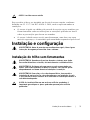
Installation and Configuration
WARNING: Before performing the following procedure, review and follow the
safety instructions that came with the system.
Installing the Tool-Less Rail Solution
WARNING: Whenever you
need to lift the system, get others to assist you.
To avoid injury, do not attempt to lift the system by yourself.
WARNING: The system is not fixed to the rack or mounted on the rails. To
avoid personal injury or damage to the system, you must adequately
support the system during installation and removal.
WARNING: To avoid a potential electrical shock hazard, a third wire safety
grounding conductor is necessary for the rack installation. The rack
equipment must provide sufficient airflow to the system to maintain proper
cooling.
CAUTION: When installing rails in a square-hole rack it is important to
ensure that the square peg slides through the square holes.

Getting Started With Your System | 4
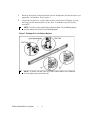
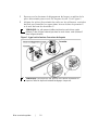
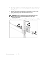
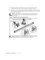
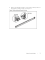
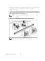
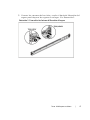
1 Push on the latch release buttons on the midpoints of the end piece t o
open the rail latches. See Figure 1.
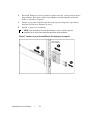
2 Align the end pieces of the rails on the vertical rack flanges to seat
the pegs in the bottom hole of the first U and the top hole of the
second U.
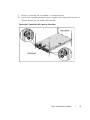
NOTE: The rails can be used in both square-hole (item 1 in the following figure)
and round-hole racks (item 2 in the following figure).
Figure 1. Pushing the Latch Release Buttons
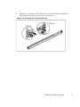
NOTE: To remove the rails, push on the latch release button on the midpoints
of the end piece and unseat each rail.


Getting Started With Your System | 6
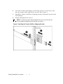
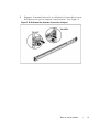
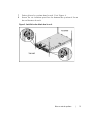
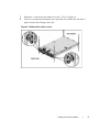
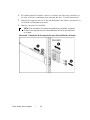
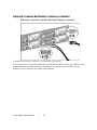
4 On each vertical rack flange on the back, put two screw bases into
the two square holes right above the rail. See Figure 3.
5 Install the chassis stabilizer shipping brackets (optional) on the back
rack flanges.
6 Install and tight en the s crews.
NOTE: To transport systems already installed in the rack, ensure that the two
chassis stabilizer shipping brackets (optional) are in place.
Figure 3. Installing the Chassis Stabilizer Shipping Brackets


Getting Started With Your System | 8
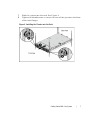
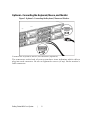
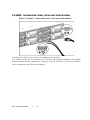
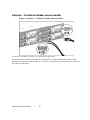
Optional—Connecting the Keyboard, Mouse, and Monitor
Figure 5. Optional—Connecting the Keyboard, Mouse and Monitor
Connect the keyboard, mouse, and monitor (optional).
The connectors on the back of your system have icons indicating which cable to
plug into each connect or. Be sure to tight en the screws (if any) on t he monitor’s
cable connector.

Getting Started With Your System | 9
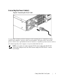
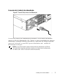
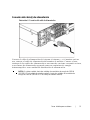
Connecting the Power Cable(s)
Figure 6. Connecting the Power Cable
Connect the system’s power cable(s) to the system and, if a monitor is used,
connect t he monitor’s p ower cable to t he monitor. Plug the other end of t he
power cables into a grounded electrical outlet or a separate power source such as
an unint errupted power supply or a p ower distribution unit.
NOTE: Your system can support up to two 1200 W power supply units (100-240 VAC
nominal input voltage) or up to two 1400 W power supply units (200-240 VAC nominal
input voltage).

Getting Started With Your System | 10
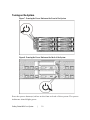
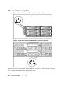
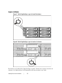
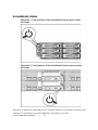
Turning on the System
Figure 7. Pressi ng the Power Button on the Front of the System
Figure 8. Pressi ng the Power Button on the Back of the System
Press the power button(s) either on the front or b ack of the system. The power
indicators should light green.

Getting Started With Your System | 11
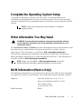
Complete the Operating System Setup
To install an operating system for the first time, see the installation and
configuration documentat ion for your operating system. Be sure the op erating
system is installed before installing hardware or software not purchased with the
system.
NOTE: See dell.com/ossupport for the latest information on supported
operating systems.
Other Information You May Need
WARNING: See the safety and regulatory information that shipped with your
system. Warranty information may be included within this document or as a
separate document.
The Hardware Owner’s Manual provides information about system features and
describes how to troubleshoot the system and install or replace system
components. This document is available at dell.com/support/manuals.
Dell systems management application documentation provides information
about installing and using the systems management software. This document is
available online at dell.com/support/manuals.
NOTE: Always check for updates on dell.com/support/manua ls and read the
updates first because they often supersede information in other documents.
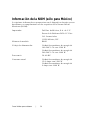
NOM Information (Mexico Only)
The following information is provided on the device described in this document
in compliance with the requirements of the official M exican st andards (NOM ):
Importer Dell Inc. de M éxico, S.A. de C.V.
Paseo de la Reforma 2620-11° Piso
Col. Lomas Atlas
11950 M éxico, D.F.
Model number B08S

Getting Started With Your System | 12
Supply voltage 100-240 V AC with 1200 W Power
Supply Unit
200-240 V AC with 1400 W Power
Supply Unit
Frequency 50/60 Hz
Current consumption 12-8 A mps w ith 1200 W Power Supply
Unit
9 Amps with 1400 W Power Supply
Unit
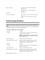
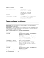
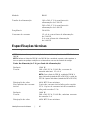
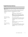
Technical Specifications
Power
NOTE: The system doesn’t support a mixed installation of 1200 W and 1400 W power supply
units.
NOTE: Both the 1200 W and 1400 W PSUs are hot swappable, and they can support hot swap in
any condition if the system has the power throttling feature.
AC power supply (per power supply)
Wattage
1200 W
Voltage 100-240 VAC, 50/60 Hz, maximum input
current: 12.0-8.0 Amps
NOTE: For 1200 W power supply, output 1200 W is for
high line (input 200-240 VAC), output 1023 W is for low
line (input 100-120 VAC).
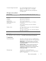
Heat dissipation
4016.251 BTU/hr maximum
Maximum inrush current Initial In-rush Current cannot exceed 55
Amps (p eak). Secondary In-rush Current
cannot exceed 35 Amps (peak).
Wattage
1400 W
Voltage 200-240 VAC, 50-60 Hz, maximum input
current: 9.0 Amps
Heat dissipation
6024.376 BTU/hr maximum.
Maximum in-rush current Initial In-rush Current cannot exceed 55
Amps (p eak). Secondary In-rush Current
cannot exceed 25 Amps (peak).

Getting Started With Your System | 13
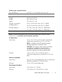
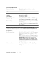
Battery (per system board)
System battery
CR 2032 3.0-V lithium ion coin cell
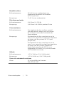
Physical
Height
8.68 cm (3.42 in)
Width
44.8 cm (17.6 in)
Depth
79.0 cm (31.1 in)
Weight (maximum
configuration)
41 kg (90.38 lb) (with 12*3.5” HDD)
39 kg (86.00 lb) (with 24*2.5” HDD)
Weight (empty) 15.7 kg (34.61 lb) (with 2.5” HDD bay)
15.1 kg (33.29 lb) (with 3.5” HDD bay)
Environmental
NOTE: For additional information about environmental measurements for specific system
configurations, see www.dell.com/environmental_datasheets.
Te mperature
Operat ing 10° to 35°C (50° to 95°F) with a maximum
temperature gradation of 10°C p er hour
NOTE: For altitudes above 2950 feet, the maximum
operating temperature is derated 1°F/550 ft.
CAUTION: The maximum number of memory modules
and hard drives supported on 1U and 2U node
configurations, with 130W (4 and 8 core) and 135W
processors, depends on the power supply installed.
St orage –40° t o 65°C (–40° to 149°F) wit h a
maximum temperature gradation of 20°C p er
hour
Relative humidity
Operat ing 20% to 80% (noncondensing) with a maximum
humidity gradation of 10% per hour
St orage
5% to 95% (noncondensing)
Maximum vibration
Operat ing
0.26 Grms at 5–350 Hz
St orage 1.88 Grms at 10–500 Hz for 15 min

Getting Started With Your System | 14
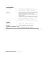
Maximum shock
Operat ing One shock pulse in the positive z axis
(one pulse on each side of the system) of 31 G
for 2.6 ms in the operational orient ation
St orage Six consecutively executed shock pulses in the
positive and negative x, y, and z axes
(one pulse on each side of the system) of 71 G
for up to 2 ms;
Six consecutively executed shock pulses in the
positive and negative x, y, and z axes
(one pulse on each side of the system) of 27 G
faired square wave pulse with velocity change
at 235 inches/second (597 centimeters/second)
Altitude
Operat ing
-15.2 to 3,048 m (-50 t o 10,000 ft.)
St orage
-15.2 to 10,668 m (-50 to 35,000 ft.)
Airborne Contaminant Level
Clas s
G1 as defined by ISA-S71.04-1985

Dell PowerEdge
C6220 II
Mise en route
du système

Remarques, précautions et
avertissements
REMARQUE : une REMARQUE indique des informations importantes qui vous
aident à mieux utiliser votre ordinateur.
PRÉCAUTION : une PRÉCAUTION indique un risque d'endommagement du
matériel ou de perte de données si les instructions ne sont pas respectées.
AVERTISSEMENT : un AVERTISSEMENT indique un risque
d'endommagement du matériel, de blessure corporelle ou de mort.
______________
Les informations que contient ce document sont sujettes à modification sans préavis.
© 2013 Dell Inc. Tous droits réservés.
La reproduct ion de ce document, sous quelque forme que ce soit , sans le consentement
écrit de Dell Inc. est strictement interdite.
Marques ut ilisées dans ce document : Dell™, le logo Dell et PowerEdge™ sont des
marques de Dell Inc. Intel® et Int el® Xeon® sont des marques déposées d'Intel
Corporat ion aux Ét ats-Unis et dans d'autres pay s. Red Hat Enterp rise Lin ux® et Ent erprise
Linux® sont des marques déposées de Red Hat, Inc. aux États-Unis et /ou dans d'aut res
pays. Novell® est une marque déposée et SUSE™ est une marque de Novell Inc. aux
États-Unis et dans d'autres pays. Citrix® et XenServer® sont des marques déposées ou
des marques de Citrix Syst ems, In c. aux Ét at s-Unis et/ou dans d'autres pays. VMware®
est une marque déposée ou une marque de VMWare, Inc. aux États-Unis ou dans
d'autres pays.
D'autres marques et noms commerciaux peuvent être ut ilisés dans ce document pour faire
référence aux entités se réclamant de ces marques ou noms ou à leurs produits. Dell Inc.
rejette tout intérêt propriétaire dans les marques et les noms commerciaux autres que
les siens.
Modèle réglementaire B08S
Mai 2013 N/P 1PFTR Rév. A00

Mise en route du système | 17
PRÉCAUTION : emplacement à accès restreint
Ce serveur est conçu pour être installé uniquement à des emplacement à accès
restreint tels que définis dans la norme Cl. 1.2.7.3 of IEC 60950-1: 2001 où les
deux conditions suivantes s'appliquent :
• Seuls peuvent accéder à ce serveur les utilisateurs ou le personnel
d'ent ret ien qui ont reçu des instructions quant aux raisons pour lesquelles
les restrictions concernant l'emplacement s'appliquent et pour lesquelles
toutes les précautions doivent être prises.
• L'accès se fait grâce à un outil ou un verrou et une clé ou d'autres moyens
de sécurité et est contrôlé par l'autorité en charge de l'emplacement.
Installation et configuration
AVERTISSEMENT : avant d'effectuer la procédure suivante, consultez et
respectez les consignes de sécurité qui accompagnent le système.
Installation sans outils de la solution rails
AVERTISSEMENT : demandez toujours de l'aide pour soulever le système.
Pour éviter de vous blesser, ne tentez pas de soulever le système
tout seul.
AVERTISSEMENT : le système n'est pas fixé au rack ni monté sur les rails.
Pour éviter de vous blesser ou d'endommager le système, assurez-vous
qu'il dispose de support au cours de son installation et de son retrait.
AVERTISSEMENT : pour réduire les risques de blessures corporelles
provoquées par d'éventuels chocs électriques, ajoutez un troisième
conducteur de mise à la masse de sécurité lors de l'installation du rack.
La ventilation fournie par l'équipement de rack doit être suffisante pour
assurer le refroidissement du système.
PRÉCAUTION : lors de l'installation de rails dans un rack à trous carrés,
il
importe de s'assurer que les ergots s'emboîtent dans les trous carrés
.

Mise en route du système | 18
1 Poussez sur les boutons de dégagement du loquet au milieu de la
pièce d'ext rémit é p our ouvrir les loquets du rail. Voir Figure 1.
2 Alignez les pièces d'extrémité des r ails sur les collerettes vert icales
du rack pour inst aller les ergots dans le trou du bas du premier U
et le trou du haut du deuxième U.
REMARQUE : les rails peuvent s'utiliser tant dans les racks à trous carrés
(élément 1 dans la figure suivante) que dans les racks à trous ronds (élément 2
dans la figure suivante).
Figure 1. Appui sur les boutons d'ouverture des loquets
REMARQUE : pour retirer les rails, poussez sur le bouton d'ouverture du
loquet au milieu de la pièce d'extrémité et dégagez chaque rail.
La pagina si sta caricando...
La pagina si sta caricando...
La pagina si sta caricando...
La pagina si sta caricando...
La pagina si sta caricando...
La pagina si sta caricando...
La pagina si sta caricando...
La pagina si sta caricando...
La pagina si sta caricando...
La pagina si sta caricando...
La pagina si sta caricando...
La pagina si sta caricando...
La pagina si sta caricando...
La pagina si sta caricando...
La pagina si sta caricando...
La pagina si sta caricando...
La pagina si sta caricando...
La pagina si sta caricando...
La pagina si sta caricando...
La pagina si sta caricando...
La pagina si sta caricando...
La pagina si sta caricando...
La pagina si sta caricando...
La pagina si sta caricando...
La pagina si sta caricando...
La pagina si sta caricando...
La pagina si sta caricando...
La pagina si sta caricando...
La pagina si sta caricando...
La pagina si sta caricando...
La pagina si sta caricando...
La pagina si sta caricando...
La pagina si sta caricando...
La pagina si sta caricando...
La pagina si sta caricando...
La pagina si sta caricando...
La pagina si sta caricando...
La pagina si sta caricando...
La pagina si sta caricando...
La pagina si sta caricando...
La pagina si sta caricando...
La pagina si sta caricando...
La pagina si sta caricando...
La pagina si sta caricando...
-
 1
1
-
 2
2
-
 3
3
-
 4
4
-
 5
5
-
 6
6
-
 7
7
-
 8
8
-
 9
9
-
 10
10
-
 11
11
-
 12
12
-
 13
13
-
 14
14
-
 15
15
-
 16
16
-
 17
17
-
 18
18
-
 19
19
-
 20
20
-
 21
21
-
 22
22
-
 23
23
-
 24
24
-
 25
25
-
 26
26
-
 27
27
-
 28
28
-
 29
29
-
 30
30
-
 31
31
-
 32
32
-
 33
33
-
 34
34
-
 35
35
-
 36
36
-
 37
37
-
 38
38
-
 39
39
-
 40
40
-
 41
41
-
 42
42
-
 43
43
-
 44
44
-
 45
45
-
 46
46
-
 47
47
-
 48
48
-
 49
49
-
 50
50
-
 51
51
-
 52
52
-
 53
53
-
 54
54
-
 55
55
-
 56
56
-
 57
57
-
 58
58
-
 59
59
-
 60
60
-
 61
61
-
 62
62
-
 63
63
-
 64
64


Dell C6220 Guida utente
- Tipo
- Guida utente
- Questo manuale è adatto anche per
in altre lingue
- français: Dell C6220 Mode d'emploi
- español: Dell C6220 Guía del usuario
- português: Dell C6220 Guia de usuario
Documenti correlati
Altri documenti
-
Aeroflex 3900 series User Programming Manual
-
Electro-Voice 7600 Manuale del proprietario
-
Mach P4MST-890 Setup Manual
-
Biostar TF7025-M2 Manuale del proprietario
-
Progress PCS740 Manuale utente
-
MUTOH Viper TX 100 Manuale utente
-
-
Electrolux WE170P Guida d'installazione
-
AEG L7FE76484 Guida d'installazione
-