
P4MST-890 Setup Manual
FCC Information and Copyright
This equipment has been tested and found to comply with the limits of a Class
B digital device, pursuant to Part 15 of the FCC Rules. These limits are designed
to provide reasonable protec tion against harmful interference in a residential
installation. This equipment generates, uses and can radiate radio frequency
energy and, if not installed and used in accordance with the instructions, may
cause harmful interference to radio communications. There is no guarantee
that interfere nce will not occur in a particular ins talla tion.
The ve ndor makes no representa tions or warra nties with respec t to the
contents here and specially disclaims any implied warranties of merchantability
o r fi tnes s fo r a ny purpose . F urthe r t he ve ndo r res e rves t he rig ht to rev is e t his
publication and to make changes to the contents here without obligation to
notify any party beforehand.
D uplication of this publication, in pa rt or in whole, is not allowed without first
obtaining the vendor’s approval in writing.
The content of this user’s manual is subject to be changed without notice and
we will not be res ponsible for any mis takes found in this user’s manual. All the
brand and product names are trademarks of their respective companies.

Table of Contents
Chapter 1: Introduction .............................................3
1.1 Before You Start...................................................................3
1.2 Package Checklist................................................................3
1.3 Motherboard Features..........................................................4
1.4 Rear Panel Connectors..........................................................5
1.5 Motherboard Layout............................................................6
Chapter 2: Hardware Installation..............................7
2.1 Installing Central Processing Unit (CPU)................................7
2.2 FAN Headers........................................................................ 9
2.3 Installing System Memory.....................................................10
2.4 Connectors and Slots............................................................11
Chapter 3: Headers & Jumpers Setup......................13
3.1 How to Setup Jumpers..........................................................13
3.2 Detail Settings.....................................................................13
Chapter 4: Useful Help ..............................................18
4.1 Driver Installation Note .......................................................18
4.2 AWARD BIOS Beep Code......................................................19
4.3 Extra Information................................................................19
4.4 Troubleshooting...................................................................21
Chapter 5: WarpSpeeder™ .......................................22
5.1 Introduction........................................................................22
5.2 System Requirement............................................................22
5.3 Installation.........................................................................23
5.4 WarpSpeeder™....................................................................24
Appendencies: SPEC In Other Language ................30
German................................................................................................30
France..................................................................................................32
Italian..................................................................................................34
Spanish................................................................................................36
Portuguese...........................................................................................38
Polish...................................................................................................40
Russian................................................................................................42
Arabic..................................................................................................44
Japanese..............................................................................................46

P4MST-890
3
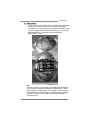
CHAPTER 1: INTRODUCTION
1.1 BEFORE YOU START
Tha nk yo u fo r choo sing our product. Before you sta rt installing the
mo the rboa rd , plea se make sure you fo llow the ins tructio ns be low:
Prepare a dry and stable working environment with
s ufficie nt ligh ting .
Always disconnect the computer from power outlet
be fore ope ra tion.
Befo re you take the mo the rboa rd ou t f rom a n ti-s ta tic
bag, ground yourself properly by touching any safely
grounde d appliance, or use gro unded wrist strap to
remove the static charge.
Avo id tou ch ing the compone nts o n mo the rboa rd o r the
rear side of the boa rd unless necessary. Hold the board
on the edge , do not try to bend or flex the board.
Do not lea ve any unfastene d small parts inside the
case after installation. Loose parts will cause short
circuits which ma y damage the equipment.
Keep the computer from dangerous area, such as heat
source , humid a ir and wa te r.
1.2 PACKAGE CHECKLIST
z HDD Cable X 1
z Use r’s Manua l X 1
z Fully Setup Driver CD X 1
z Rear I/O Panel for ATX Case X 1
z FDD Cable X 1 (optional)
z Se ria l ATA Cab le X 1 (op tiona l)
z USB 2.0 Cable X1 (optional)
z S/PDIF Cable X 1 (optional)
z Se ria l ATA Po we r Cab le X 1 (o ptio nal)

Motherboard Manual
4
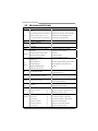
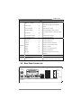
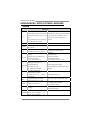
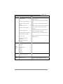
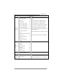
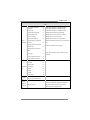
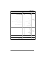
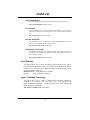
1.3 MOTHERBOARD FEATURES
SPEC
CPU
LGA 775
Intel Core 2Duo
/
Pe ntium 4
/
Pe ntium D
/
Celeron D pr ocessor up to 3.8 GHz
*It is recommended to use processors
with 95W power consumption.
Supports Hy per Tra nsport/ Execute Disable
Bit/ Enhanced Intel S peedStep®/ Intel
Extended Memory 64 technology
FSB 533 / 80 0 / 106 6 MHz
Chipset
VIA P4M890
VIA VT8237A
Graphic Integrated i n U niChrome Pro Chipset Max Share d Video Memory is 64 MB
Super I/O
ITE IT 87 12F
Provides the most commonly used
legacy Super I/O functionality.
Low Pin C ount Interf ace
Environment Control initiatives,
H/W Monitor
Fan Spee d Co ntroller
ITE's "Smart G uardia n" fu nc tion
Main
Memory
DIMM Slots x 2
Supports DDR2 533
Each DIMM supports
256/512MB/1GB/2GB DDR2
Max Memory C apicity 4GB
Single Channel Mode DDR2 memory module
Registered DIMM and ECC DIMM is not
supported
IDE Integrated I DE Controller
Ultra DMA 33~133 Bus Master Mode
supports PIO Mo de 0~4,
SATA Integrated Seri al ATA Controller
Data transfer rates up to 1.5 Gb/s.
SATA Version 1.0 specification compliant.
LAN PHY Realtek RTL 8201CL PHY
10 / 100 Mb/s auto negotiation
Half / Full duplex capability
Sound
Codec
ALC861VD
5.1 cha nnels a udio o ut
High- Defi nition Au dio s upport
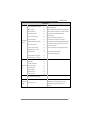
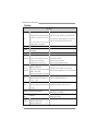
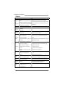
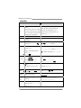
PCI Express x 16 slot x1 Supports PCI express x16 expansion cards
PCI Express x 1 slot x1 Supports PCI express x1 expansion cards Slots
PCI slot x2 Supports PCI expansion cards
Floppy connector x1 Each connector supports 2 Floppy drives
IDE Connector x2 Each connector supports 2 IDE device
SATA Connector x2 Each connector supports 1 SATA devices
Front Panel Connector x1 Supports front panel facilities
Front Audi o Co nnector x1 Supports front panel a udio fu nction
On Board
Connector
CD-in Co nnec tor x1 Supports CD au dio-in f unc tion

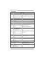
P4MST-890
5
SPEC
S/PDIF o ut co nnector x1 Supports di gital a udio out fu nction
CPU Fan hea der x1
CPU Fan power s upply (with Smart Fa n
function )
System Fan header x1 System Fan Power supply
Clear CMOS head er x1 Restore CMO S data to fac tory d efa ult
USB connector x2
Each connector supports 2 front panel USB
ports
Power Connector (24pin) x1 Connects to Power supply
Power Connector (4pin) x1 Connects to Power supply
Back Panel
I/O
PS/2 Keyb oard x1
PS/2 Mouse x1
Serial Port x1
Printer Port x1
VGA Port x1
LAN port x1
USB Port x4
Audio Jack x3
Connects to PS/2 Keyboard
Connects to PS/ 2 Mo us e
Provide RS- 232 Serial connection
Connects to various types of device
Connects to mo nitor.
Connects to RJ-45 ethernet cable
Connects to USB devices
Provide A udio-I n/Out a nd microphone
connection
Board Size 190 mm (W) x 24 4 mm (L) Micro ATX form Fac tor
OS
Support
Windows 2000 / XP
Biostar Reserves the right to add or remove
support for any OS with or without notice.
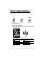
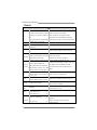
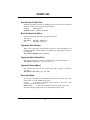
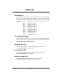
1.4 REAR PANEL CONNECTORS
PS/2
Mouse
PS/2
Keyboard
USBX2USBX2
LAN
COM1 VGA
Printer Port
Line I n /
Surround
Line Out
Mic In 1/
Bass/ Center

Motherboard Manual
6
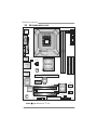
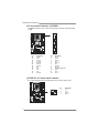
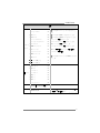
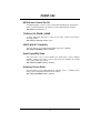
1.5 MOTHERBOARD LAYOUT
Super
I/O
DIMM1
DIMM2
FDD1
PCI-EX1_1
PCI-EX16
PCI 1
PCI2
JPANEL1
JUSB2
JUSB3
JATXPWR1
JCFAN1
JATXPWR2
JSAT A1
JSATA2
Codec
JCDIN1
JSFAN1
BAT 1
BIOS
VIA
VT8237A
LGA775
CPU1
P4M890
JAUDIOF1
JKBMS1
JUSB1
JUSBLAN1
C
O
M
1
J
C
O
M
1
JVGA1
JAUDIO1
JSPDIF_OUT1
IDE1
JC MOS 1
LAN
IDE2
JUSBV2
JUSBV1
JP RNT 1
No te: represents the 1■
st
pin.

P4MST-890
7
CHAPTER 2: HARDWARE INSTALLATION
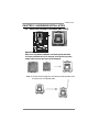
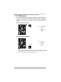
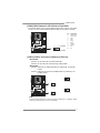
2.1 INSTALLING CENTRAL PROCESSING UNIT (CPU)
Special Notice:
Remove Pin Cap before installation, and make good preservation
for future use. When the CPU is removed, cover the Pin Cap on the
empty socket to ensure pin legs won’t be damaged.
Pin Cap
Step 1: Pull the socket locking lever out from the socket and then raise
the lever up to a 90-degree angle.

Motherboard Manual
8
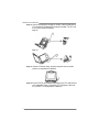
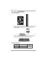
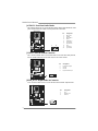
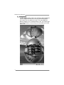
Step 2: Look for the triangular cut edge on socket, and the golden dot on
CPU should point forwards this triangular cut edge. The CPU will
fit only in the correct orientation.
Step 2-1:
Step 2-2:
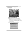
Step 3: Hold the CPU down firmly, and then lower the lever to locked
position to complete the installation.
Step 4: Put the CPU Fan and heatsink assembly on the CPU and buckle it
on the retention frame. Connect the CPU FAN power cable into
the JCFAN1. This completes the installation.

P4MST-890
9
2.2 FAN HEADERS
These fan headers support cooling-fans built in the computer. The fan
cable and connector may be different according to the fan manufacturer.
Connect the fan cable to the connector while matching the black wire to
pin#1.
JCFAN1: CPU Fan Header
Pin
Assignment
1 Ground
2 +12V
3 FAN RPM rate
sense
14
JCFAN1
4 Smart Fan
Control
JSFAN1: System Fan Header
Pin
Assignment
1 Ground
2 +12V
13
JSFAN1
3 FAN RPM rate
sense
Note:
The JSFAN1 support 3-pi n head connector. When connecti ng with wires onto connectors,
please note that the red wire is the positi ve and should be connected to pin#2, and the
black wire is Ground and should be c onnected to GND.

Motherboard Manual
10
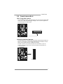
2.3 INSTALLING SYSTEM MEMORY
A. Memory Modules
DIMM1
DIMM2
1. Unlock a DIMM slot by pressing the retaining clips outward. Align a
DIMM on the slot such that the notch on the DIMM matches the
break on the Slot.
2. Insert the DIMM vertically and firmly into the slot until the retaining
chip snap back in place and the DIMM is properly seated.
B. Memory Capacity
DIMM Socket
Location
DDR Module
To t a l Me m o r y
Size
DIMM1 256MB/512MB/1GB/2GB
DIMM2 256MB/512MB/1GB/2GB
Max is 4GB.

P4MST-890
11
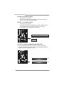
2.4 CONNECTORS AND SLOTS
FDD1: Floppy Disk Connector
The motherboard provides a standard floppy disk connector that supports 360K,
720K, 1.2M, 1.44M and 2.88M floppy disk types. This connector supports the
provided floppy drive ribbon cables.
34
33
1
2
IDE1/IDE2: Hard Disk Connectors
The motherboard has a 32-bit Enhanced PCI IDE Controller that provides PIO
Mode 0~4, Bus Master, and Ultra DMA 33/66/100/133 functionality. It has two
HDD connectors IDE1 (primary) and IDE2 (secondary).
The IDE connectors can connect a master and a slave drive, so you can
connect up to four hard disk drives. The first hard drive should always be
connected to IDE1.
IDE2IDE1
21
3940

Motherboard Manual
12
PCI-EX16: PCI-Express x16 Slot
- PCI-Express 1.0a compliant.
- Maximum theoretical realized bandwidth of 4GB/s simultaneously per
direction, for an aggregate of 8GB/s totally.
PCI-EX1_1: PCI-Express x1 Slot
- PCI-Express 1.0a compliant.
- Data transfer bandwidth up to 250MB/s per direction; 500MB/s in total.
- PCI-Express supports a raw bit-rate of 2.5Gb/s on the data pins.
- 2X bandwidth over the traditional PCI architecture.
PCI-EX16
PCI-EX1_1
PCI1~PCI2: Peripheral Component Interconnect Slots
This motherboard is equipped with 2 standard PCI slots. PCI stands for
Peripheral Component Interconnect, and it is a bus standard for expansion
cards. This PCI slot is designated as 32 bits.
PCI1
PCI2

P4MST-890
13
CHAPTER 3: HEADERS & JUMPERS SETUP
3.1 HOW TO SET UP JUMPERS
The illustration shows how to set up jumpers. When the jumper cap is
placed on pins, the jumper is “close”, if not, that means the jumper is
“open”.
Pin opened Pin closed Pin1-2 closed
3.2 DETAIL SET T ING S
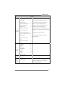
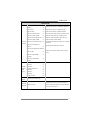
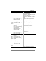
JPANEL1: Front Panel Header
This 16-pin connector includes Power-on, Reset, HDD LED, Power LED, Sleep
button and speaker connection. It allows user to connect the PC case’s front
panel switch functions.
1
8
16
SLP
PWR_LED
On/Off
RST
HLED
SPK
++
+
9
-
-
Pin Assignment Functio n Pin Assignment Functio n
1 +5V 9 Sleep control
2 N/A 10 Ground
Sleep button
3 N/A 11 N/A N/A
4 Speaker
Speaker
Connector
12 Power LED (+)
5 HDD LED (+) 13 Power LED (+)
6 HDD LED (-)
Hard drive
LED
14 Power LED (-)
Power LED
7 Ground 15 Power button
8 Reset control
Reset button
16 Ground
Power-on button

Motherboard Manual
14
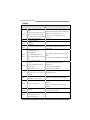
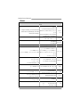
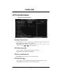
ATX Power Source Connector: JATXPWR1
JATXPWR1 allows user to connect 24-pin power connector on the ATX power
supply.
1
12
13
24
Pin Assignment Pin Assignment
13 +3.3V 1 +3.3V
14 -12V 2 +3.3V
15 Ground 3 Ground
16 PS_ON 4 +5V
17 Ground 5 Ground
18 Ground 6 +5V
19 Ground 7 Ground
20 NC 8 PW_OK
21 +5V 9 Standby Voltage+5V
22 +5V 10 +12V
23 +5V 11 +12V
24 Ground 12 +3.3V
JATXPWR2: ATX Power Source C onnector
By connecting this connector, it will provide +12V to CPU power circuit.
Pin
Assignment
1 +12V
2 +12V
3 Ground
1
23
4
4 Ground

P4MST-890
15
JUSB2/JUSB3: Headers for USB 2.0 Ports at Front Panel
This header allows user to connect additional USB cable on the PC front panel,
and also can be connected with internal USB devices, like USB card reader.
Pin
Assignment
1 +5V (fused)
2 +5V (fused)
3 USB-
4 USB-
5 USB+
6 USB+
7 Ground
8 Ground
9 Key
1
2
9
10
JUSB2
JUSB3
10 NC
JUSBV1/JUSBV2: Power Source Headers for USB Ports
Pin 1-2 Close:
JUSBV1: +5V for USB ports at JUSB1/JUSBLAN1.
JUSBV2: +5V for USB ports at front panel (JUSB2/JUSB3).
Pin 2-3 Close:
JUSBV1: USB ports at JUSB1/JUSBLAN1 are powered by +5V standby
voltage.
JUSBV2: USB ports at front panel (JUSB2/JUSB3) are powered by +5V
standby voltage.
31
Pin 1-2 close
13
JUSBV1
JUSBV2
13
3
1
Pin 2-3 close
Note:
In order to support this function “Power-On system vi a USB device,” “JUSBV1/ JUSBV2”
jumper cap should be placed on Pin 2-3 individuall y.

Motherboard Manual
16
JAUDIOF1: Front Panel Audio Header
This header allows user to connect the front audio output cable with the PC front
panel. It will disable the output on back panel audio connectors.
Pin Assignment
1 Mic Left in
2 Ground
3 Mic Right in
4 GPIO
5 Right line in
6 Jack Sense
7 Front Sense
8 Key
9 Left line in
10 Jack Sense
19
210
JCDIN1: CD-ROM Audio-in Connector
This connector allows user to connect the audio source from the variaty devices,
like CD-ROM, DVD-ROM, PCI sound card, PCI TV turner card etc.
Pin
Assignment
1 Left Channel Input
2 Ground
3 Ground
14
4 Right Channel Input
JSPDIF_OUT1: Digital Audio-out Connector
This connector allows user to connect the PCI bracket SPDIF output header.
Pin
Assignment
1 +5V
2 SPDIF_OUT
13
3 Ground

P4MST-890
17
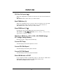
JCMOS1: Clear CMOS Header
By placing the jumper on pin2-3, it allows user to restore the BIOS safe setting
and the CMOS data, please carefully follow the procedures to avoid damaging
the motherboard.
13
Pin 1-2 Close:
Normal Operation (default).
13
13
Pin 2-3 Close:
Clear CMOS data.
※ Clear CMOS Procedures:
1. Remove AC power line.
2. Set the jumper to “Pin 2-3 close”.
3. Wait for five seconds.
4. Set the jumper to “Pin 1-2 close”.
5. Power on the AC.
6. Reset your desired password or clear the CMOS data.
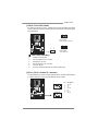
JSATA1~JSATA2: Serial ATA Connectors
The motherboard has a PCI to SATA Controller with 2 channels SATA interface,
it satisfies the SATA 1.0 spec and with transfer rate of 1.5Gb/s.
Pin
Assignment
1 Ground
2 TX+
3 TX-
4 Ground
5 RX-
6 RX+
147
JSATA1
JSATA2
147
7 Ground

Motherboard Manual
18
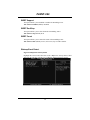
CHAPTER 4: USEFUL HELP
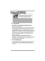
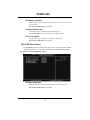
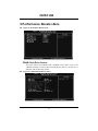
4.1 D
RIVER INSTALLATION NOTE
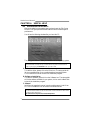
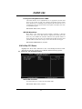
After you installed your operating system, please insert the Fully Setup
Driver CD into your optical drive and install the driver for better system
performance.
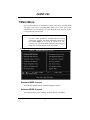
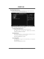
You will see the following window after you insert the CD
The setup guide will auto detect your motherboard and operating system.
Note:
If this window didn’t show up after you ins ert the Driver CD, please use file browser to
locate and execute the file SETUP.EXE under your optical drive.
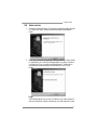
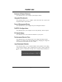
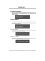
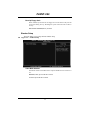
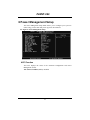
A. Driver Installation
To install the driver, please click on the Driver icon. The setup guide will
list the compatible driver for your motherboard and operating system.
Click on each device driver to launch the installation program.
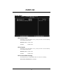
B. Software Installation
To install the software, please click on the Software icon. The setup guide
will list the software available for your system, click on each software title
to launch the installation program.
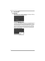
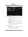
C. Manual
Aside from the paperback manual, we also provide manual in the Driver
CD. Click on the Manual icon to browse for available manual.
Note:
You will need Acrobat Reader to open the manual file. Please download the latest version
of Acrobat Reader software from
http://www.adobe.com/products/acrobat/readstep2.html

P4MST-890
19
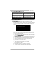
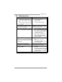
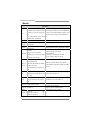
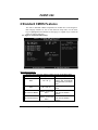
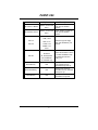
4.2 AWARD BIOS BEEP CODE
Beep Sound Meaning
One long beep followed by two short
beeps
Video card not found or video card
memory bad
High-low siren sound CPU overheated
System will shut down automatically
One Short beep when system boot-up No error found during POST
Long beeps every other second No DRAM detected or install
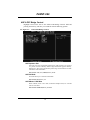
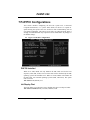
4.3 EXT RA INFORMATION
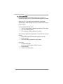
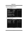
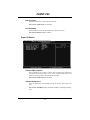
A. BIOS Update
After you fail to update BIOS or BIOS is invaded by virus, the
Boot-Block function will help to restore BIOS. If the following message
is shown after boot-up the system, it means the BIOS contents are
corrupted.
In this Case, please follow the procedure below to restore the BIOS:
1. Make a bootable floppy disk.
2. Download the Flash Utility “AWDFLASH.exe” from Machspeed's
website
3. C
onfirm motherboard model and download the respectively BIOS
from Biostar website.
4. Copy “AWDFLASH.exe” and respectively BIOS into floppy disk.
5. Insert the bootable disk into floppy drive and press Enter.
6. System will boot-up to DOS prompt.
7. Type
“Awdflash xxxx.bf/sn/py/r” in DOS prompt.
(
xxxx means BIOS name.)
8. System will update BIOS automatically and restart.
9. The BIOS has been recovered and will work properly.

Motherboard Manual
20
B. CPU Overheated
If the system shutdown automatically after power on system for
seconds, that means the CPU protection function has been activated.
When the CPU is over heated, the motherboard will shutdown
automatically to avoid a damage of the CPU, and the system may not
power on again.
In this case, please double check:
1. The CPU cooler surface is placed evenly with the CPU surface.
2. CPU fan is rotated normally.
3. CPU fan speed is fulfilling with the CPU speed.
After confirmed, please follow steps below to relief the CPU protection
function.
1. Remove the power cord from power supply for seconds.
2. Wait for seconds.
3. Plug in the power cord and boot up the system.
Or you can:
1. Clear the CMOS data.
(See “Close CMOS Header: JCMOS1” section)
2. Wait for seconds.
3. Power on the system again.
La pagina si sta caricando...
La pagina si sta caricando...
La pagina si sta caricando...
La pagina si sta caricando...
La pagina si sta caricando...
La pagina si sta caricando...
La pagina si sta caricando...
La pagina si sta caricando...
La pagina si sta caricando...
La pagina si sta caricando...
La pagina si sta caricando...
La pagina si sta caricando...
La pagina si sta caricando...
La pagina si sta caricando...
La pagina si sta caricando...
La pagina si sta caricando...
La pagina si sta caricando...
La pagina si sta caricando...
La pagina si sta caricando...
La pagina si sta caricando...
La pagina si sta caricando...
La pagina si sta caricando...
La pagina si sta caricando...
La pagina si sta caricando...
La pagina si sta caricando...
La pagina si sta caricando...
La pagina si sta caricando...
La pagina si sta caricando...
La pagina si sta caricando...
La pagina si sta caricando...
La pagina si sta caricando...
La pagina si sta caricando...
La pagina si sta caricando...
La pagina si sta caricando...
La pagina si sta caricando...
La pagina si sta caricando...
La pagina si sta caricando...
La pagina si sta caricando...
La pagina si sta caricando...
La pagina si sta caricando...
La pagina si sta caricando...
La pagina si sta caricando...
La pagina si sta caricando...
La pagina si sta caricando...
La pagina si sta caricando...
La pagina si sta caricando...
La pagina si sta caricando...
La pagina si sta caricando...
La pagina si sta caricando...
La pagina si sta caricando...
La pagina si sta caricando...
La pagina si sta caricando...
La pagina si sta caricando...
La pagina si sta caricando...
La pagina si sta caricando...
La pagina si sta caricando...
La pagina si sta caricando...
La pagina si sta caricando...
La pagina si sta caricando...
La pagina si sta caricando...
La pagina si sta caricando...
La pagina si sta caricando...
La pagina si sta caricando...
La pagina si sta caricando...
La pagina si sta caricando...
La pagina si sta caricando...
-
 1
1
-
 2
2
-
 3
3
-
 4
4
-
 5
5
-
 6
6
-
 7
7
-
 8
8
-
 9
9
-
 10
10
-
 11
11
-
 12
12
-
 13
13
-
 14
14
-
 15
15
-
 16
16
-
 17
17
-
 18
18
-
 19
19
-
 20
20
-
 21
21
-
 22
22
-
 23
23
-
 24
24
-
 25
25
-
 26
26
-
 27
27
-
 28
28
-
 29
29
-
 30
30
-
 31
31
-
 32
32
-
 33
33
-
 34
34
-
 35
35
-
 36
36
-
 37
37
-
 38
38
-
 39
39
-
 40
40
-
 41
41
-
 42
42
-
 43
43
-
 44
44
-
 45
45
-
 46
46
-
 47
47
-
 48
48
-
 49
49
-
 50
50
-
 51
51
-
 52
52
-
 53
53
-
 54
54
-
 55
55
-
 56
56
-
 57
57
-
 58
58
-
 59
59
-
 60
60
-
 61
61
-
 62
62
-
 63
63
-
 64
64
-
 65
65
-
 66
66
-
 67
67
-
 68
68
-
 69
69
-
 70
70
-
 71
71
-
 72
72
-
 73
73
-
 74
74
-
 75
75
-
 76
76
-
 77
77
-
 78
78
-
 79
79
-
 80
80
-
 81
81
-
 82
82
-
 83
83
-
 84
84
-
 85
85
-
 86
86


in altre lingue
- English: Mach P4MST-890
Altri documenti
-
Biostar N68S3B Manuale utente
-
Biostar G31-M4 Setup Manual
-
-
-
-
-
-
-
-