AJA UDC Installation and Operation Guide
- Categoria
- Apparecchiature musicali supplementari
- Tipo
- Installation and Operation Guide

UDC Mini-Converter
Up/Down/Cross-Converter
Version 2.7r2
Published December 10, 2019
Installation and Operation Guide

UDC Mini-Converter v2.7r2 2 www.aja.com
Notices
Trademarks
AJA® and Because it matters.® are registered trademarks of AJA Video Systems, Inc.
for use with most AJA products. AJA™ is a trademark of AJA Video Systems, Inc. for
use with recorder, router, software and camera products. Because it matters.™ is a
trademark of AJA Video Systems, Inc. for use with camera products.
CION®, Corvid Ultra®, lo®, Ki Pro®, KONA®, KUMO®, ROI® and T-Tap® are registered
trademarks of AJA Video Systems, Inc.
AJA Control Room™, KiStor™, Science of the Beautiful™, TruScale™, TruZoom™,
V2Analog™ and V2Digital™ are trademarks of AJA Video Systems, Inc.
All other trademarks are the property of their respective owners.
Copyright
Copyright © 2019 AJA Video Systems, Inc. All rights reserved. All information in
this manual is subject to change without notice. No part of the document may be
reproduced or transmitted in any form, or by any means, electronic or mechanical,
including photocopying or recording, without the express written permission of AJA
Video Systems, Inc.
Contacting AJA Support
When calling for support, have all information at hand prior to calling. To contact AJA
for sales or support, use any of the following methods:
Telephone +1.530.271.3190
FAX +1.530.271.3140
Web https://www.aja.com
Support Email suppor[email protected]
Sales Email [email protected]

UDC Mini-Converter v2.7r2 3 www.aja.com
Contents
Notices . . . . . . . . . . . . . . . . . . . . . . . . . . . . . . . . . . . . . .2
Trademarks . . . . . . . . . . . . . . . . . . . . . . . . . . . . . . . . . . . . . . . . . . . 2
Copyright . . . . . . . . . . . . . . . . . . . . . . . . . . . . . . . . . . . . . . . . . . . . 2
Contacting AJA Support . . . . . . . . . . . . . . . . . . . . . . . . . . . . . . . . . . . 2
Chapter 1 – Introduction . . . . . . . . . . . . . . . . . . . . . . . . . . .4
Overview. . . . . . . . . . . . . . . . . . . . . . . . . . . . . . . . . . . . . . . . . . . . .4
Video Formats. . . . . . . . . . . . . . . . . . . . . . . . . . . . . . . . . . . . . . . .4
Features. . . . . . . . . . . . . . . . . . . . . . . . . . . . . . . . . . . . . . . . . . . . 4
Block Diagram . . . . . . . . . . . . . . . . . . . . . . . . . . . . . . . . . . . . . . . . . 5
I/O Connections . . . . . . . . . . . . . . . . . . . . . . . . . . . . . . . . . . . . . . . . 5
Conversion Mode Discussion and Examples . . . . . . . . . . . . . . . . . . . . . . 5
Upconvert Mode . . . . . . . . . . . . . . . . . . . . . . . . . . . . . . . . . . . . . . 5
Downconvert Mode . . . . . . . . . . . . . . . . . . . . . . . . . . . . . . . . . . . . 6
SD Aspect Ratio Convert . . . . . . . . . . . . . . . . . . . . . . . . . . . . . . . . . 8
Installation . . . . . . . . . . . . . . . . . . . . . . . . . . . . . . . . . . . . . . . . . . 9
User Controls . . . . . . . . . . . . . . . . . . . . . . . . . . . . . . . . . . . . . . . . . . 9
Using DIP Switches to Control the UDC . . . . . . . . . . . . . . . . . . . . . . . . . 9
DIP Switch Settings. . . . . . . . . . . . . . . . . . . . . . . . . . . . . . . . . . . . 10
DIP Switches 4 & 5 (FMT0, FMT1) . . . . . . . . . . . . . . . . . . . . . . . . . . . 10
Chapter 2 – Operation . . . . . . . . . . . . . . . . . . . . . . . . . . . .11
USB Control and Setup—Using AJA Mini-Cong . . . . . . . . . . . . . . . . . . 11
Acquiring Mini-Cong. . . . . . . . . . . . . . . . . . . . . . . . . . . . . . . . . . 11
Installing Mini-Cong . . . . . . . . . . . . . . . . . . . . . . . . . . . . . . . . . . 11
Running Mini-Cong. . . . . . . . . . . . . . . . . . . . . . . . . . . . . . . . . . . 13
Operating Mini-Cong . . . . . . . . . . . . . . . . . . . . . . . . . . . . . . . . . 14
Tabbed Screens . . . . . . . . . . . . . . . . . . . . . . . . . . . . . . . . . . . . . . 15
Video Tab Screen. . . . . . . . . . . . . . . . . . . . . . . . . . . . . . . . . . . . . . . 16
HDMI Tab Screen . . . . . . . . . . . . . . . . . . . . . . . . . . . . . . . . . . . . . . . 18
Audio Tab Screen . . . . . . . . . . . . . . . . . . . . . . . . . . . . . . . . . . . . . . 20
Update Tab Screen. . . . . . . . . . . . . . . . . . . . . . . . . . . . . . . . . . . . . . 21
Info Tab Screen . . . . . . . . . . . . . . . . . . . . . . . . . . . . . . . . . . . . . . . . 22
Appendix A – Specications . . . . . . . . . . . . . . . . . . . . . . . . 23
UDC Tech Specs . . . . . . . . . . . . . . . . . . . . . . . . . . . . . . . . . . . . . . . 23
Appendix B – Safety and Compliance . . . . . . . . . . . . . . . . . .25
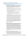
Warranty and Liability Information . . . . . . . . . . . . . . . . . . . .33
Limited Warranty on Hardware. . . . . . . . . . . . . . . . . . . . . . . . . . . . . . 33
Limitation of Liability . . . . . . . . . . . . . . . . . . . . . . . . . . . . . . . . . . . . 33
Governing Law and Language; Your Rights. . . . . . . . . . . . . . . . . . . . . . 33
Index. . . . . . . . . . . . . . . . . . . . . . . . . . . . . . . . . . . . . . .35

UDC Mini-Converter v2.7r2 4 www.aja.com
Chapter 1 – Introduction
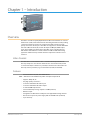
Overview
The UDC is a broadcast quality Up/Down/Cross Mini-Converter that can convert
between 3G-A, HD, and SD video formats. Borrowing from AJA’s industry leading
conversion technology used in our model FS2, the UDC provides very high
quality conversions at a low price. The UDC also supports 16-channel embedded
SDI audio. I/Os include 3G, HD, and SD-SDI Input and Output, HDMI output,
and 2-channel RCA-style audio output. The UDC can be controlled by local
DIP switches with additional control available via USB and AJA’s Mini-Config
application. A Reference Input allows the video output to be timed to a local
reference.
Video Formats
The UDC does not convert frame rates—it works with the input frame rate.
The only exception is a 3:2 function where 23.98 is converted to 59.94 (and 24
is converted to 60). If a reference is provided, it must be in the same frame rate
hierarchy as the input video (e.g., 23.98/29.97/59.94, 25/50, or 24/30/60).
Features
• Converts between SD, HD, and 3G HD formats
NOTE: UDC converts 3G-A formats only. It does not input or output 3G-B.
• Supports 1080p 50, 60
• Very high quality conversions
• 16-channel embedded SDI audio input
• 16-channel embedded SDI audio output
• 8-channel HDMI output audio
• 2-channel RCA-style analog outputs at -10dBV (nominal)
• Reference Input
• Congurable via DIP switch or USB port and supplied Mini-Cong software
• Uses universal input +5V power supply AJA model DWP-U-R1 (included)
• 5-year warranty

UDC Mini-Converter v2.7r2 5 www.aja.com
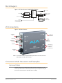
Block Diagram
Figure 1. UDC Mini-Converter, Simplified Block Diagram
Up,
Down,
and
Cross
Converter
Audio
D/A
Video
Audio
HDMI
Transmitter
Video with Embedded Audio
2-Channel
Analog Audio
Monitor Output
HDMI 1.4a Output
with Embedded
Audio
SDI Input
SDI Output
SDI Receiver
Reference Input
USB Port
(connect to PC or Mac)
Selects 8 or 10-bit Video
and other Functions
Genlock
I/O Connections
Figure 2. UDC Mini-Converter
DC Power
Input
SDI Output
Connector
SDI Input
BNC
Unbalanced
Analog Audio
Outputs
(2 RCA Jacks)
USB Port
HDMI
Output
Connector
Lock LED
Reference
Input
NOTE: The Lock LED indicates valid input video by color. Green is SD video, red is HD
video, amber is 3G video, off is no input.
Conversion Mode Discussion and Examples
Upconvert Mode
The UDC allows you to select the type of Upconversion performed on an SD
source input. This mode is in effect only when the input is SD (525i or 625i) and
the selected output format is HD (720p, 1080i, or 1080p).

UDC Mini-Converter v2.7r2 6 www.aja.com
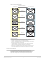
Figure 3. Upconvert Mode Examples
Upconvert Illustrations
Full Screen
4:3 Pillar
LB to Full
14:9 Pillar
Wide Zoom
16
9
4
3
4:3 Upconverts To These displays on 16:9
Selection Description
• Full Screen – 4x3 image is stretched horizontally to ll a 16x9 frame.
• 4x3 Pillar – 4x3 image at center screen with black sidebars.
• LB to Full – 4x3 letterboxed image is scaled to t horizontally in a 16x9 frame.
Black bars top and bottom are cropped o.
• 14x9 Pillar (default) – 4x3 image is scaled to create a 14x9 image with black
sidebars and slightly cropping top and bottom of original image.
• Wide Zoom – A combination of scaling and stretching is used to t to a 16x9
frame. Slight cropping of top and bottom and a small aspect ratio change.
Downconvert Mode
This mode determines the type of Downconversion performed on the
selected HD source input. See the following Downconvert Illustrations for
Downconversion examples. This mode is in effect only when the input is HD
(720p, 1080i, or 1080p) and the selected output format is SD (525i or 625i).

UDC Mini-Converter v2.7r2 7 www.aja.com
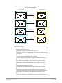
Figure 4. Downconvert Mode Example
16
9
Downconvert Illustrations
Anamorphic
Letterbox
4
3
16:9 Downconverts To These displays on 4:3
Crop
14:9
Selection Description
• Letterbox – Image is reduced with black top and bottom added to image area,
with the aspect ratio preserved.
• Crop (default) – Image is cropped to t new screen size.
• Anamorphic – HD image is converted to full-screen SD with a 16x9 aspect ratio
(anamorphic).
• 14:9 – Image is reduced slightly with aspect ratio preserved. Black is added top
and bottom, and the left and right sides are cropped.
• Auto AFD – Automatically selects the best Downconvert mode based on the
input video's Active Format Description (AFD) code.
Active Format Description (AFD) codes are carried in the vertical ancillary
(VANC) portion of HD SDI video signals, specified in SMPTE 2016 as follows:
“AFD information is intended to guide DTV receivers and/or intermediate
professional video equipment regarding the display of video of one aspect
ratio on a display of another aspect ratio.”
In the UDC Downconverter, the AFD code on the video input can be used
to guide the Downconverter in choosing which mode to use to best display
the important content of the16:9 HD input video on the 4:3 SD output. For
example, if the input AFD code is 10 (Full Frame), it means that the input video
has important picture information throughout the full 16:9 frame, so the
Downconverter should use Letterbox mode to be sure none of the content
is cropped off. An AFD code of 9 (Pillarbox) says that the input video only has

UDC Mini-Converter v2.7r2 8 www.aja.com
content within the center 4:3 area of the picture (usually because it originally
came from an Upconverted SD signal) so the Downconverter Crop mode
would be the best choice. There are 16 possible HD AFD codes, of which 8 are
in common use. The UDC does not process or use SD AFD codes.
SD Aspect Ratio Convert
This mode selects the type of SD-to-SD Aspect Ratio Conversion (ARC) performed
on an incoming selected SD source. This mode is in effect only when the input
and output are both SD (525i or 625i). (In Europe 16:9 anamorphic video is also
known as “wide screen” video.)
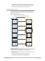
Figure 5. SD Aspect Ratio Conversion Examples
SD Aspect Ratio Conversion Illustrations
H Crop
Pillarbox
V Crop
14:9
Off
(no conversion)
Letterbox
4
3
4:3 Converts To These displays on 4:3
Selection Descriptions
• O–Turns aspect ratio conversion O.
• Letterbox–Converts 16:9 Anamorphic video to Letterbox video.
• H Crop–Converts 16:9 Anamorphic video to 4:3 Standard video (crops left and
right edges of video).
• Pillarbox–Converts 4:3 Standard video to 16:9 Anamorphic video.
• V Crop–Converts Letterbox video to 16:9 Anamorphic video.
• 14:9–Converts 16:9 Anamorphic video to 14:9 Cropped video.

UDC Mini-Converter v2.7r2 9 www.aja.com
Installation
Typically, UDC installation consists of the following steps:
1. Ensure the converter is disconnected from power.
2. Connect video equipment to the converter BNCs and HDMI connector.
3. Connect audio equipment to RCA connectors (optional)
4. Apply power to the converter (AJA power supply included).
5. The converter will now run using the default factory settings. If you wish to
alter the factory settings, you’ll need to:
• Install the AJA Mini-Cong software on your computer
• Attach the converter via USB
• Make your changes using Mini-Cong setup screens.
• This process is detailed in "Chapter 2 Operation" on page 11.
User Controls
The UDC can be used right out of the box for many applications, since it is
designed to recognize inputs and perform standard actions automatically.
However, you can also manually configure the UDC using either of two methods:
• Mini-Cong software application supplied for PCs and Macs
• DIP switches accessible via a cutout on the back of the UDC case
One of the DIP switches is a “Local/Remote” switch. When in the “Local” mode,
the remaining DIP switches support a subset of the user controls. When in the
“Remote” mode, the normal Mini-Converter non-volatile registers control the unit
(as last set).
Refer to "Chapter 2 Operation" on page 11 for information about controlling the
UDC with Mini-Config. Instructions for DIP switch settings are presented below.
Using DIP Switches to Control the UDC
Figure 6. DIP Switches
In addition to the Mini-Config application, you can also control the unit via an
8-switch DIP, accessible through a cut-out in the bottom of the unit.
The default positions are shown in Figure 6. The default settings result in an
output of 1080i59.94 with NTSC related inputs and 1080i50 with PAL related
inputs.
For 1080p23.98/1080psf23.98 inputs, the input can be converted to 720p23.98,
1080p23.98, 1080i59.94, or 1080p59.94. The latter two would use the 3:2 DIP
switch to add 3:2 pulldown.
The compliance label, found on the back of the UDC, lists the DIP switch settings.
NOTE: HDMI monitors may not support all frame rates or "pSF" formats.
NOTE: UDC converts 3G-A formats only. It does not input or output 3G-B.

UDC Mini-Converter v2.7r2 10 www.aja.com
DIP Switch Settings
The functions of the DIP switches and what they control are described in the
following tables.
Table 1. DIP Switch Setting Descriptions
SWITCH FUNCTION DIP Set LEFT (default) DIP Set RIGHT
1 Control Selects LOCAL (DIP), and
blocks Mini-Cong control.
When in “Local” mode, the
remaining DIP switches will
support a subset of the user
controls.
Selects REMOTE (Mini-Cong),
and disables DIP switches 2-8.
When in “Remote” mode, the
normal Mini-Cong non-
volatile registers (as last set),
control the unit.
2 HD/SD Selects HD output mode. Selects SD output mode.
3 1080/720 (HD mode only) Selects 1080 output. Selects 720 output.
4 & 5 Alternate HD formats. These two DIP switches (FMT0, FMT1) act together to select
alternate HD output formats. Zero (0) is Left position, one (1) is
Right position.
See Table 2 below for setting information.
6 3:2 Conversion (23.98/24
inputs only)
3:2 conversion is OFF.
A 23.98/24 fps input results in
a 23.98/24 fps output.
3:2 conversion is ON.
A 23.98/24 fps input results in
either a 29.97/30 or 59.94/60
fps output.
7 Up Conversion Sets upconversion to Sidebar
(SIDEB).
Sets upconversion to Full
screen (FULL).
8 Down Conversion Sets downconversion to
Letterbox (LTRBX).
Sets downconversion to Full
screen (FULL).
DIP Switches 4 & 5 (FMT0, FMT1)
DIP switches 4 and 5 together select alternate HD formats. Switches 1 and 2 can
also affect the HD output format. In the table below an X indicates a “Don’t Care”
setting.
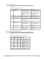
Table 2. Output Formats for DIP Switch 2,3, 4, & 5 Settings
SW2
HD/SD
SW3
1080/720
SW 4
FMT0
SW 5
FMT1
Output
Left Left Left Left 1080i 25/29.97/30
Left Left Left Right 1080pSF
23.98/24/25/29.97/30
Left Left Right Left 1080p 50/59.94/60
Left Left Right Right 1080p
23.98/24/25/29.97/30
Left Right X Left 720p 50/59.94/60
Left Right X Right 720p
23.98/24/25/29.97/30
Right X X X 525i/625i

UDC Mini-Converter v2.7r2 11 www.aja.com
Chapter 2 – Operation
USB Control and Setup—Using AJA Mini-Config
Your AJA Mini-Converter can be used right out of the box for some applications
since it is designed to recognize inputs and perform standard actions
automatically by default. However, to use its full capability, you must use AJA’s
Mini-Config software application for PCs and Macs. This same application can be
used to update to new Mini-Converter software released by AJA.
NOTE: DIP switch 1 must be ON (Remote, Right) to permit Mini-Config control of the unit.
Acquiring Mini-Config
AJA’s Mini-Config application is available for download from the AJA website.
To download the latest Mini-Config package, which includes the Mini-Config
application, Mini-Converter firmware, and documentation, go to:
https://www.aja.com/products/mini-config-software
Select either the Windows or Mac icon to download the desired version.
Mini-Converter Documentation
Included with the Mini-Config package is a complete set of documentation for
all Mini-Converters supported by Mini-Config. A .PDF of the Installation and
Operation Guide for the currently connected Mini-Converter can be accessed from
the Mini-Config UI via the Help/Manual drop-down menu.
Documentation for all AJA Mini-Converters that use Mini-Config can also be
accessed directly in the Mini-Config download package Documentation folder,
and via the Documentation icon available on the Mac installer.
Documentation (and firmware) included with the Mini-Config application are the
versions available at the time of distribution. However, Mini-Converter software,
firmware and documentation are updated regularly, so newer versions may exist.
To download the latest documentation for an individual Mini-Converter, go to:
https://www.aja.com/family/mini-converters
and navigate to the Support web page of that Mini-Converter.
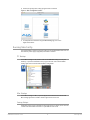
Installing Mini-Config
PC Installation
To install Mini-Config on a Windows PC:
1. Download the application from the AJA website (select the Windows icon
on the Mini-Cong Support web page).
2. Open the AJA_MiniCong.zip le
3. Double-click on the MiniInstaller.msi le.
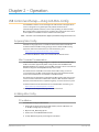
4. A Setup Wizard will guide you through the installation.

UDC Mini-Converter v2.7r2 12 www.aja.com
Figure 7. Mini-Config PC Setup Wizard
5. Click Next to begin. Answer the questions in the subsequent dialogues.
When nished, an AJA Mini-Cong shortcut will be installed on the desktop,
and you will be able to locate the Mini-Cong application in the AJA folder
in the Programs listing.
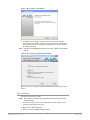
NOTE: If the Mini-Config application already exists on the PC, a different Setup Wizard
appears.
Figure 8. Mini-Config Setup Wizard, Reinstallation
With this screen you can Repair (reinstall) or Remove (uninstall) Mini-Config on
the PC.
Mac Installation
To install the application on a Mac:
NOTE: Mac computers must be Intel-based (G5, G4 and earlier models will not work
with Mini-Config).
1. Download the application from the AJA website (select the Apple icon on
the Mini-Cong Support web page).
2. Open the AJA_MiniCong folder.
3. Double-click on the AJAMiniCong.dmg le.

UDC Mini-Converter v2.7r2 13 www.aja.com
4. Answer the prompt and a utility program will be launched.
Figure 9. Mini-Config Mac Installer
5. To complete the installation drag the MiniCong.app icon to the
Applications folder.
Running Mini-Config
Connect the Mini-Converter to the PC or Mac via the supplied USB cable. Connect
the external power supply (supplied) to the Mini-Converter.
PC Startup
To run Mini-Config on a PC, double-click on the AJA Mini-Config icon on your
desktop, or open the AJA folder in the program list and click on the AJA Mini-
Config application located inside the Mini-Config folder.
Mac Startup
To run Mini-Config on a Mac, open the Applications folder and locate the AJA
Mini-Config application. Double-click the application to launch it.
Saving Setups
A File drop down menu on the Mini-Config application bar allows you to save the
current state of the Mini-Converter to a preset file for later recall.

UDC Mini-Converter v2.7r2 14 www.aja.com
Using this feature you can set up the converter for different applications, storing
each configuration (Save Preset As...) with a unique name for easy recall (Open
Preset...).
A Revert to Factory Settings menu item similarly allows you to change the
settings back to AJA’s factory defaults.
Operating Mini-Config
The Mini-Config application provides a graphic interface for viewing settings
and updating software. It consists of an information area at the top that shows
the available Mini-Converters attached to the computer via USB, with a graphical
rendering of the selected Mini-Converter showing all the connectors and their
current state.
Colored text next to the connectors indicates the signal type and what the Mini-
Converter is doing:
• Blue text indicates the values automatically selected
• Black text indicates values that you have manually selected
• Red text indicates the Mini-Converter is not detecting a signal, or cannot
operate with the current user settings.
NOTE: Even if no output device is detected, the SDI connector text still shows the signal it
is outputting.
NOTE: Configuration settings in red will change based on the attached output device as
well as input signals. For improved accuracy and reliability, you should configure
the Mini-Converter only when the target output device is attached and input
signals are supplied at the inputs.
Screens are virtually the same on both PC and Mac, with subtle differences that
reflect the general look of the platform environment.

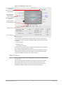
UDC Mini-Converter v2.7r2 15 www.aja.com
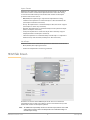
Figure 10. Example Mini-Config Screen
Select a USB port and
an attached
Mini-Converter (name
in parentheses).
Each connector is
labeled with the
signals currently
detected or manually
selected.
Firmware Version
and Serial Number
Status Message
Tabbed Screens
Selecting a Mini-Converter with the pulldown menu causes this application to
connect to the selected converter. The graphic of Mini-Converter and text below
it provides:
• Type of converter
• Firmware version
• Serial number of the unit.
A status field at the bottom of the screen shows if your application is connected
and communicating with the Mini-Converter.
When configuring the Mini-Converter, select it from the top pulldown, view the
current settings and change any values. Making a change communicates that
new value to the Mini-Converter’s non-volatile memory.
Tabbed Screens
The Tabs delineate control screens with groups of controls for each type of task to
be performed.
The controls for the actual configuration parameters are specific to each Mini-
Converter type. When you Click on any of the tab buttons, the pane below
the tabs will change to match your tab selection. Any changes you make are
immediately applied and will be saved, overwriting previous settings.

UDC Mini-Converter v2.7r2 16 www.aja.com
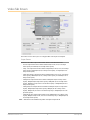
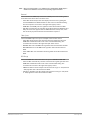
Video Tab Screen
The Video Screen is where you can configure UDC video inputs and outputs.
Output Format
Determines the UDC output video format. These are the format choices:
• SD: The output video format will be 525i59.94 (for 23.98, 29.97, or 59.94 fps
video inputs) or 625i50 (for 25 or 50 fps video inputs).
• 720p: - The output video format will be 720p59.94 (for 23.98, 29.97, or 59.94 fps
video inputs), 720p60 (for 24, 30, or 60 fps video inputs), or 720p50 (for 25 or
50 fps video inputs).
• 1080i: The output video format will be 1080i59.94 (for 23.98, 29.97, or 59.94 fps
video inputs), 1080i60 (for 24, 30, or 60 fps video inputs), or 1080i50 (for 25 or
50 fps video inputs).
• 1080psf: The output video format will be 1080psf23.98 (for 23.98 fps video
inputs), 1080psf24 (for 24 fps video inputs), 1080psf25 (for 25 or 50 fps video
inputs), 1080psf29.97 (for 29.97 or 59.94 video inputs), or 1080psf30 (for 30 or
60 fps video inputs).
• 1080p (low): The output video format will be 1080p23.98 (for 23.98 fps video
inputs), 1080p24 (for 24 fps video inputs), 1080p25 (for 25 or 50 fps video
inputs), 1080p29.97 (for 29.97 or 59.94 video inputs), or 1080p30 (for 30 or 60
fps video inputs).
• 1080p (high): The output video format will be 1080p50 (for 25 or 50 fps video
inputs), 1080p59.94 (for 23.98, 29.97 or 59.94 video inputs), or 1080p60 (for 24,
30 or 60 fps video inputs).
NOTE: UDC converts 3G-A formats only. It does not input or output 3G-B.

UDC Mini-Converter v2.7r2 17 www.aja.com
Add 3:2 Pulldown
When the Add 3:2 Pull down box is checked, 23.98 fps and 24 fps video inputs
are converted to 29.97 fps and 30 fps, respectively, by adding 3:2 pull down
before conversion. Note that this selection is only used when the UDC module
is in Remote mode (DIP switch #1). In Local mode, 3:2 pull down addition is
determined by DIP switch #6.
Genlock
Determines the timing reference for the UDC video output. The selected
reference is displayed to the right of the Genlock pull-down. These are the
choices:
• Auto (default): Auto uses the reference input if present, or locks to the
SDI input if no reference is present or if the reference is present but is not
compatible.
• Lock to Input: Always locks to the SDI input.
• Lock to Reference: Always locks to the Reference input – if the supplied
reference is not compatible, reverts to Free Run.
• Free Run: Always operates in Free Run mode.
Up Convert
Determines the mode when converting from SD input video to an HD output
video format. This selection is only used when the UDC module is in Remote
mode (DIP switch #1). In Local mode, the up convert mode is determined by DIP
switch #7. These are the choices:
• 4x3 Pillar: Produces 4x3 image at center screen with black sidebars.
• 14x9 Pillar (default): Produces 14x9 image, zoomed slightly to ll a 14x9 image
with black sidebars.
• Full Screen: Produces anamorphic full screen display.
• LB to Full Image: Produces image zoomed to t the full screen (letterbox).
• Wide Zoom: Produces an image sized to t a 16x9 screen using a combination
of zoom and stretch. (This can introduce a small aspect ratio change.)
Down Convert
Determines the mode when converting from HD input video to an SD output
video format. Note that this selection is only used when the UDC module is in
Remote mode (DIP switch #1). In Local mode, the upconvert mode is determined
by DIP switch #8. These are the choices:
• Crop (default): Image is cropped to t new screen size.
• Anamorphic: HD image is converted to full-screen SD with a 16x9 aspect ratio
(anamorphic).
• 14x9: Image is reduced slightly with aspect ratio preserved. Black is added top
and bottom, and the left and right sides are cropped.
• Auto AFD: Automatically selects the best Downconvert mode based on the
input video's Active Format Description (AFD) code. If the input video is not
carrying an AFD VANC code, the Downconverter defaults to crop.
• Letterbox: Image is reduced with black top and bottom added to image area,
with the aspect ratio preserved.

UDC Mini-Converter v2.7r2 18 www.aja.com
Aspect Convert
Determines the mode when converting from SD input video to an SD output
video format. There is no DIP switch equivalent for this control. The setting
is saved in nonvolatile memory in the module and used for all subsequent
operation. These are the choices:
• O (default): The input image is copied to the output with no scaling.
• Letterbox: The input frame is scaled vertically to a 16x9 "letterboxed" size
(anamorphic to letterbox conversion).
• H Crop: The input frame is scaled horizontally to 16x9, then center-cropped
(anamorphic to center crop conversion).
• Pillarbox: The input frame is scaled horizontally to make a pillarbox output
(4x3 to anamorphic conversion).
• V Crop: The input frame is scaled vertically to make a vertically cropped
output (letterbox to anamorphic conversion).
• 14x9: The input frame is scaled horizontally and vertically as a compromise
between H Crop and Letterbox (anamorphic to 14x9 conversion).
Loss of Input
Determines what action is taken when input video is lost. These are the choices:
• Black (default): The output goes to black.
• Freeze: The output freezes on the last good frame.
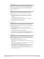
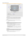
HDMI Tab Screen
Provides user selection of the HDMI output modes. There is no DIP switch
equivalent for these controls. The setting is saved in nonvolatile memory in the
module and used for all subsequent operation.
NOTE: The HDMI video output always mirrors the SDI video output, both in content and
output format selection. Click on the Output tab to view and make changes to
the UDC output settings.

UDC Mini-Converter v2.7r2 19 www.aja.com
NOTE: When the output format is set to 1080psf23.98 or 1080psf24 the HDMI output is
disabled since HDMI does not have a corresponding supported format.
Protocol
Selects whether the HDMI output uses DVI or HDMI protocols for sending video
to the destination device. These are the choices:
• Auto: UDC automatically selects the output protocol based on getting the
attached HDMI device's EDID information. This is the recommended setting.
The selected protocol is shown to the right of the popup control.
• HDMI: UDC uses HDMI protocols regardless of the attached device's EDID.
• DVI: UDC uses DVI protocols regardless of the attached device's EDID. Because
DVI protocols do not support audio or HDMI InfoFrame ancillary data, select
this mode only if you know that the attached device requires it.
Color Space
Selects the HDMI output color space and depth. These are the choices:
• Auto: UDC automatically selects the mode based on getting the attached
HDMI device's EDID information. This is the recommended setting. The
selected mode is shown to the right of the pull-down control.
• RGB 8Bit: UDC uses 8-bit RGB mode regardless of the attached device's EDID.
• RGB 10Bit: UDC uses 10-bit RGB mode regardless of the attached device's
EDID.
• YCbCr 10Bit: UDC uses 10-bit YCbCr mode regardless of the attached device's
EDID.
RGB Range
Selects the HDMI video levels when the Color Space is RGB 8Bit or RGB 10Bit.
• Auto: The UDC automatically selects the mode based on getting the attached
HDMI device's EDID information. This is the recommended setting. The
selected mode is shown to the right of the popup control.
• SMPTE: The UDC scales the output video level to 8-bit range 16 - 235 (10-bit 64
- 940) regardless of the attached device's EDID.
• Full Range: The UDC scales the output video level to 8-bit range 0 - 255 (10-bit
0 - 1023) regardless of the attached device's EDID.

UDC Mini-Converter v2.7r2 20 www.aja.com
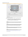
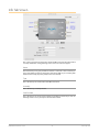
Audio Tab Screen
The Audio Screen is where you can configure UDC HDMI and analog (RCA-style)
audio output channels. Pull down menu settings are described following the
screen graphic. There is no DIP switch equivalent for these controls. The setting
is saved in nonvolatile memory in the module and used for all subsequent
operation.
NOTE: The SDI embedded output audio is a channel-for-channel copy of the input SDI
embedded audio. There are no user controls.
HDMI Audio
Selects how many SDI channels are passed to the HDMI connector and which
channel pairs are selected. These are the choices:
• Auto: The UDC automatically selects the audio output conguration based
on communicating with the attached HDMI device. The resulting mode is
displayed to the right of the popup control.
• 2 Channel: Outputs a pair of channels from the SDI stream to two channels
on the HDMI output connector. The selected audio pair is determined by the
Analog Audio setting (below).
• 8 Channel: Outputs SDI channels 1 through 8 to the HDMI output connector.
Analog Audio
Selects the channel pair that will be output to the Analog RCA connectors (L/R)
and the HDMI audio output (when HDMI Audio is in 2-channel mode). These are
the choices:
• Channel 1+2, Channel 3+4, Channel 5+6, Channel 7+8, Channel 9+10,
Channel11+12, Channel 13+14, Channel 15+16
La pagina sta caricando ...
La pagina sta caricando ...
La pagina sta caricando ...
La pagina sta caricando ...
La pagina sta caricando ...
La pagina sta caricando ...
La pagina sta caricando ...
La pagina sta caricando ...
La pagina sta caricando ...
La pagina sta caricando ...
La pagina sta caricando ...
La pagina sta caricando ...
La pagina sta caricando ...
La pagina sta caricando ...
La pagina sta caricando ...
-
 1
1
-
 2
2
-
 3
3
-
 4
4
-
 5
5
-
 6
6
-
 7
7
-
 8
8
-
 9
9
-
 10
10
-
 11
11
-
 12
12
-
 13
13
-
 14
14
-
 15
15
-
 16
16
-
 17
17
-
 18
18
-
 19
19
-
 20
20
-
 21
21
-
 22
22
-
 23
23
-
 24
24
-
 25
25
-
 26
26
-
 27
27
-
 28
28
-
 29
29
-
 30
30
-
 31
31
-
 32
32
-
 33
33
-
 34
34
-
 35
35


AJA UDC Installation and Operation Guide
- Categoria
- Apparecchiature musicali supplementari
- Tipo
- Installation and Operation Guide
Documenti correlati
-
AJA HB-R-SDI Installation and Operation Guide
-
AJA ROI-DP Istruzioni per l'uso
-
-
AJA HD10MD4 Manuale utente
-
-
-
AJA HDP3 Manuale utente
-
-
-
AJA KONA 3G Installation and Operation Guide