Asus Q670EA-IM-A Manuale del proprietario
- Categoria
- Schede madri
- Tipo
- Manuale del proprietario

Industrial Motherboard
Q670EA-IM-A

ii
E21891
Revised Edition V2
March 2023
Copyright © 2023 ASUSTeK COMPUTER INC. All Rights Reserved.
No part of this manual, including the products and software described in it, may be reproduced,
transmitted, transcribed, stored in a retrieval system, or translated into any language in any form or by any
means, except documentation kept by the purchaser for backup purposes, without the express written
permission of ASUSTeK COMPUTER INC. (“ASUS”).
Product warranty or service will not be extended if: (1) the product is repaired, modified or altered, unless
such repair, modification of alteration is authorized in writing by ASUS; or (2) the serial number of the
product is defaced or missing.
ASUS PROVIDES THIS MANUAL “AS IS” WITHOUT WARRANTY OF ANY KIND, EITHER EXPRESS
OR IMPLIED, INCLUDING BUT NOT LIMITED TO THE IMPLIED WARRANTIES OR CONDITIONS OF
MERCHANTABILITY OR FITNESS FOR A PARTICULAR PURPOSE. IN NO EVENT SHALL ASUS, ITS
DIRECTORS, OFFICERS, EMPLOYEES OR AGENTS BE LIABLE FOR ANY INDIRECT, SPECIAL,
INCIDENTAL, OR CONSEQUENTIAL DAMAGES (INCLUDING DAMAGES FOR LOSS OF PROFITS,
LOSS OF BUSINESS, LOSS OF USE OR DATA, INTERRUPTION OF BUSINESS AND THE LIKE),
EVEN IF ASUS HAS BEEN ADVISED OF THE POSSIBILITY OF SUCH DAMAGES ARISING FROM ANY
DEFECT OR ERROR IN THIS MANUAL OR PRODUCT.
SPECIFICATIONS AND INFORMATION CONTAINED IN THIS MANUAL ARE FURNISHED FOR
INFORMATIONAL USE ONLY, AND ARE SUBJECT TO CHANGE AT ANY TIME WITHOUT NOTICE,
AND SHOULD NOT BE CONSTRUED AS A COMMITMENT BY ASUS. ASUS ASSUMES NO
RESPONSIBILITY OR LIABILITY FOR ANY ERRORS OR INACCURACIES THAT MAY APPEAR IN THIS
MANUAL, INCLUDING THE PRODUCTS AND SOFTWARE DESCRIBED IN IT.
Products and corporate names appearing in this manual may or may not be registered trademarks or
copyrights of their respective companies, and are used only for identification or explanation and to the
owners’ benefit, without intent to infringe.

iii
Contents
Chapter 1 Product Overview
1.1 Package contents......................................................................... 1-1
1.2 Features ........................................................................................ 1-1
1.3 Specifications ............................................................................... 1-2
Chapter 2: Motherboard information
2.1 Before you proceed ..................................................................... 2-1
2.2 Motherboard layout ...................................................................... 2-2
2.3 Central Processing Unit (CPU) ................................................... 2-4
2.3.1 CPU installation .............................................................. 2-5
2.3.2 CPU heatsink and fan assembly installation ................... 2-7
2.4 System memory ........................................................................... 2-9
2.5 Jumpers ...................................................................................... 2-10
2.6 Connectors ................................................................................. 2-16
2.6.1 Rear panel connectors .................................................. 2-16
2.6.2 Internal connectors ....................................................... 2-18
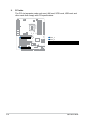
2.7 Slot .............................................................................................. 2-31
Chapter 3: BIOS setup
3.1 BIOS Setup program .................................................................... 3-1
3.2 Main menu .................................................................................... 3-2
3.3 Advanced menu ........................................................................... 3-2
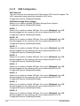
3.3.1 PCH-FW Configuration ................................................... 3-2
3.3.2 Trusted Computing ......................................................... 3-3
3.3.3 CPU Configuration .......................................................... 3-4
3.3.4 Graphics Configuration ................................................... 3-5
3.3.5 Power Management ....................................................... 3-5
3.3.6 PCI Express Configuration .............................................. 3-6
3.3.7 Super IO Configuration ................................................... 3-8
3.3.8 Serial Console Redirection ........................................... 3-10
3.3.9 SATA Configuration ...................................................... 3-13
3.3.10 VMD setup menu .......................................................... 3-13
3.3.11 Network Stack Configuration ........................................ 3-13
3.3.12 USB Configuration ........................................................ 3-14
3.3.13 NVMe Configuration ...................................................... 3-15

iv
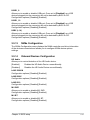
3.3.14 Onboard Devices Configuration .................................... 3-15
3.3.15 APM Configuration ........................................................ 3-16
3.3.16 EZ-Flash ....................................................................... 3-17
3.3.17 Watchdog Timer ............................................................ 3-18
3.4 Hardware Monitor menu ............................................................ 3-18
3.5 Security menu ............................................................................ 3-19
3.5.1 Administrator Password ................................................ 3-19
3.5.2 User Password .............................................................. 3-20
3.5.3 Secure Boot .................................................................. 3-20
3.6 Boot menu .................................................................................. 3-21
3.7 Exit menu .................................................................................... 3-21
Appendix
Notices .......................................................................................................A-1
Service and Support .................................................................................A-5

1-1
Chapter 1: General information
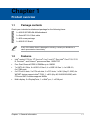
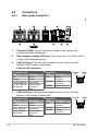
1.1 Package contents
Check your industrial motherboard package for the following items.
1 x ASUS Q670EA-IM-A Motherboard
1 x Serial ATA 6.0 Gb/s cable
1 x M.2 screw package
1 x ASUS I/O Shield
If any of the above items is damaged or missing, contact your distributor or
sales representative immediately.
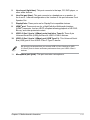
1.2 Features
• Intel® socket 1700 for 13th Gen Intel® Core™ and 12th Gen Intel® Core™ i9/ i7/ i5/
i3, Pentium®, and Celeron® processors Max. 125W TDP
• Four Dual Channel DDR5 U-DIMMs up to 128GB
• 7 x SATA 6.0 Gb/s, 6 x USB 3.2 Gen 2, 4 x USB 3.2 Gen 1, 4 x USB 2.0,
6 x COM ports
• 2 x PCIe x16 slots, 3 x PCIe x4 slots, 2 x PCI slots, 1 x M.2 (Key E, 2230) for
WiFi/BT device supports Intel® CNVi, 1 x M.2 (Key M, 2242/2260/2280) with
PCIe and SATA modes supports NVMe
• Multi-display: 2 x DisplayPorts, 1 x HDMI® port, 1 x VGA port
Chapter 1
Product overview

Q670EA-IM-A
1-2
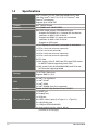
1.3 Specifications
(continued on the next page)
CPU
Intel® socket 1700 for 13th Gen Intel® Core™ and
12th Gen Intel® Core™ i9/ i7/ i5/ i3, Pentium®, and
Celeron® processors
Supports up to 125W TDP
Chipset Intel® Q670E Chipset
Memory 4 x U-DIMM, max. 128GB, DDR5
Graphics
Multi-VGA output support: DP/HDMI/VGA ports
- Supports 2x DisplayPort 1.4 outputs with a maximum
resolution of 4096 x 2160 @ 60 Hz
- Supports an HDMI® 2.1 output with a maximum
resolution of 4096 x 2160 @ 30 Hz
- Supports a VGA output
Expansion slots
1 x PCI Express 5.0 x16 slot (1 x16 mode / 2 x8 modes)*
1 x PCIe 4.0 x4 slot (x4 mode, open slot)
1 x PCIe 5.0 x16 slot (x8 mode)
1 x PCIe 3.0 x4 slot (x4 mode, open slot)
1 x PCIe 4.0 x4 slot (x4 mode, open slot)
2 x PCI slots
1 x M.2 socket 1 (Key E, 2230) with PCIe and CNVi modes
for WiFi/BT devices supporting Intel® CNVi
1 x M.2 socket 3 (Key M, 2242/2260/2280) with PCIe and
SATA modes supporting NVMe
Storage 7 x SATA 6.0 Gb/s ports
Supports RAID 0,1,5,10
LAN
3 x Intel® Lan controllers:
1 x Intel® I210AT
1 x Intel® I226V
1 x Intel® I226LM (Intel vPro supported)
Audio Realtek ALC897 High Definition Audio CODEC
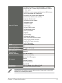
Rear panel I/O ports
1 x HDMI® port
2 x DisplayPorts
1 x VGA port
6 x USB 3.2 Gen 2 ports (5 x Type-A + 1 x Type-C®)
3 x LAN (RJ45) ports
1 x COM port (RS232/422/485)
3 x Audio jacks (Line-Out, Line-In, Mic in)

1-3
Chapter 1: General information
Internal I/O ports
5 x COM Port headers (1 x RS232/422/485, 4 x RS232)
2 x USB 3.2 Gen 1 headers support additional 4 USB 3.2
Gen 1 ports
2 x USB 2.0 headers support adddtional 4 x USB 2.0 ports
1 x CPU Fan header with PWM mode
3 x Chassis Fan headers with PWM mode
1 x Front Panel Audio header (AAFP)
1 x System Panel header
1 x Chassis Intrusion header
1 x Speaker header
1 x S/PDIF header
1 x I2C header
1 x Clear CMOS header
1 x COM Debug header
1 x LPT port header
1 x Buzzer
1 x PS/2 header
1 x Disable ME jumper
1 x AT/ATX mode selection header
1 x 24-pin ATX Power connector
1 x 8-pin ATX Power connector
1 x SPI TPM header
GPIO 1 x 8-bit GPIO header
Watch dog timer Yes
Power requirement AT mode / ATX mode
Operation Temperature 0~60°C
Non-Operation
Temperature -40~85°C
Relative Humidity 40°C @ 10%~95%
OS support
Windows® 10 (64-bit)
Windows® IoT Enterprise
Ubuntu
RedHat Enterprise
Fedora Workstation
OpenSUSE
Certification CE, FCC, BSMI, VCCI, RCM, CE-LVD
Form Factor ATX Form Factor, 305cm x 244cm
Specifications are subject to change without notice. Please refer to the ASUS
website for the latest specifications.

Q670EA-IM-A
1-4

2-1
Chapter 2: Motherboard information
Chapter 2
Motherboard information
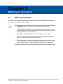
2.1 Before you proceed
Take note of the following precautions before you install motherboard components
or change any motherboard settings.
• Unplug the power cord from the wall socket before touching any
component.
• Before handling components, use a grounded wrist strap or touch a safely
grounded object or a metal object, such as the power supply case, to avoid
damaging them due to static electricity.
• Hold components by the edges to avoid touching the ICs on them.
• Whenever you uninstall any component, place it on a grounded antistatic
pad or in the bag that came with the component.
• Before you install or remove any component, always remove the AC power
by unplugging the power cord from the power outlet. Failure to do so may
cause severe damage to the motherboard, peripherals, or components.

Q670EA-IM-A
2-2
PCIEX16(G5)_1
PCIEX16(G5)_2
PCI_2
PCI_1
PCIEX4(G4)_1
PCIEX4(G4)_2
PCIEX4(G3)
ASM
1083
TPM
128Mb
BIOS
SPEAKER
CHASSIS
F_PANEL
COM2_SEL
AAFP
SPDIF_OUT
COM1_SEL
ATX_PWR
CHA_FAN2
CHA_FAN1
CPU_FAN
CHA_FAN3
Super
I/O
ALC
897
DIGI+
VRM
24.4cm(9.6in)
DDR5 DIMM_A1 (64bit, 288-pin module)
LGA1700
BATTERY
M.2(SOCKET3)
PCIE SATA IRST
4.0 X4 V V
DDR5 DIMM_A2 (64bit, 288-pin module)
DDR5 DIMM_B1 (64bit, 288-pin module)
DDR5 DIMM_B2 (64bit, 288-pin module)
AUDIO
LAN2_U32G2_34
LAN3_U32G2_78
LAN1_U32G2_1
Intel®
H670
Intel®
i226V
Intel®
i226LM
Intel®
i210AT
EATX12V
COM4COM3COM2 COM5 COM6 USB_1112
USB_1314
SATA6G_4 SATA6G_5
SATA6G_6
I2C
SATA6G_7
SATA6G_2SATA6G_1 SATA6G_3
KBMS_CON
GPIO_CON
LPT
COM_DEBUG
SMBCLK_SW
SMBDATA_SW
M.2(WIFI)
AT_ATX_SEL
DIS_ME
CLRTC
2260
2242 2280
DP1
DP2
VGA
30.5cm(12in)
1st
U32G1_910U32G1_56
HDMI
COM1
251 3 4 1
1
11416 151716161616 182021 192324
2
1
6
1
1
1
7
1
11
1
9
1
10
12
13
22
29
26
25
29
25
26
21
28
27
BUZZER
8
8
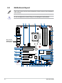
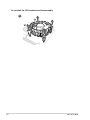
2.2 Motherboard layout
Place this side
towards the rear
of the chassis
Place nine screws into the holes indicated by circles to secure the motherboard
to the chassis.
Do not overtighten the screws! Doing so can damage the motherboard.

2-3
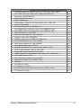
Chapter 2: Motherboard information
Connectors/Jumpers/Slots Page
1. CPU and Chassis Fan headers (4-pin CPU_FAN, 4-pin CHA_FAN1-3) 2-21
2. ATX Power connectors (24-pin ATX_PWR, 8-pin EATX12V) 2-28
3. M.2 socket 3 (M.2(SOCKET3)) 2-24
4. Intel® LGA1700 CPU socket 2-4
5. DDR5 U-DIMM slots 2-9
6. USB 3.2 Gen 1 connector (20-10 pin U32G1_910 / U32G1_56) 2-18
7. M.2 Wi-Fi (M.2(WIFI)) 2-24
8. SATA 6.0Gb/s ports (7-pin SATA6G_1-7) 2-23
9. PCIe SMBus Data Connection jumper (3-pin SMBDATA_SW) 2-10
10. PCIe SMBus Clock Connection jumper (3-pin SMBCLK_SW) 2-10
11. SPI TPM header (14-1 pin TPM) 2-20
12. Chassis Intrude header (4-1 pin CHASSIS) 2-14
13. Speaker header (4-pin SPEAKER) 2-23
14. USB 2.0 header (10-1 pin USB1112 / USB1314) 2-19
15. System Panel header (10-1 pin F_PANEL) 2-22
16. Serial Port connectors (10-1 pin COM2-6) 2-25
17. Clear CMOS header (2-pin CLRTC) 2-15
18. Keyboard and Mouse Port connector (8-pin KBMS_CON) 2-30
19. AT/ATX mode selection (3-pin AT_ATX_SEL) 2-12
20. Disable ME Update jumper (3-pin DIS_ME) 2-13
21. COM1/2 Ring/+5V/+12V selection (6-pin COM1_SEL, COM2_SEL) 2-11
22. LPT header (26-1 pin LPT) 2-18
23. Front Panel Audio header (10-1 pin AAFP) 2-27
24. Digital Audio header (4-1 pin SPDIF_OUT) 2-26
25. PCI slots 2-32
26. PCI Express x4 slots 2-31
27. I2C header (6-1 pin I2C) 2-29
28. General purpose input/output connector (10-pin GPIO_CON) 2-20
29. PCI Express x16 slots 2-31

Q670EA-IM-A
2-4
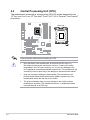
Unplug all power cables before installing the CPU.
• Upon purchase of the motherboard, ensure that the PnP cap is on
the socket and the socket contacts are not bent. Contact your retailer
immediately if the PnP cap is missing, or if you see any damage to the
PnP cap/socket contacts/motherboard components. The manufacturer will
shoulder the cost of repair only if the damage is shipment/transit-related.
• Keep the cap after installing the motherboard. The manufacturer will
process Return Merchandise Authorization (RMA) requests only if the
motherboard comes with the cap on the socket.
• The product warranty does not cover damage to the socket contacts
resulting from incorrect CPU installation/removal, or misplacement/loss/
incorrect removal of the PnP cap.
2.3 Central Processing Unit (CPU)
The motherboard comes with a surface mount LGA1700 socket designed for the
13th Gen Intel® Core™ and 12th Gen Intel® Core™ i9/ i7/ i5/ i3, Pentium®, and Celeron®
processors.
LGA1700

2-5
Chapter 2: Motherboard information
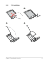
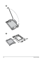
2.3.1 CPU installation
1
2 3

Q670EA-IM-A
2-6
4
5

2-7
Chapter 2: Motherboard information
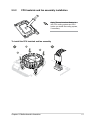
2.3.2 CPU heatsink and fan assembly installation
To install the CPU heatsink and fan assembly
B
A
A
B
12
Apply Thermal Interface Material to
the CPU cooling system and CPU
before you install the cooling system,
if necessary.

Q670EA-IM-A
2-8
To uninstall the CPU heatsink and fan assembly
A
B
B
A
1

2-9
Chapter 2: Motherboard information
2.4 System memory
The motherboard comes with Dual Inline Memory Modules (DIMM) slots designed
for DDR5 (Double Data Rate 5) memory modules.
A DDR5 memory module is notched differently from a DDR, DDR2, DDR3, or
DDR4 module. DO NOT install a DDR, DDR2, DDR3, or DDR4 memory module
to the DDR5 slot.
DIMM_B1*
DIMM_B2
DIMM_A1*
DIMM_A2
Recommended memory configurations
DIMM_A2* DIMM_A2*
DIMM_B2*
DIMM_A1
DIMM_A2*
DIMM_B1
DIMM_B2*

Q670EA-IM-A
2-10
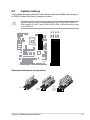
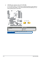
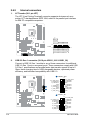
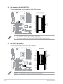
2.5 Jumpers
1. PCIe SMBus Data Connection jumper (3-pin SMBDATA_SW)
This jumper allows you to enable or disable PCIe SMbus Data Connection.
Set this jumper to pins 1-2 to enable (set to enabled by default) PCIe SMbus
Data Connection and to pins 2-3 to disable it.
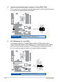
2. PCIe SMBus Clock Connection jumper (3-pin SMBCLK_SW)
This jumper allows you to enable or disable PCIe SMbus Clock Connection.
Set this jumper to pins 1-2 to enable (set to enabled by default) PCIe SMbus
Clock Connection and to pins 2-3 to disable it.
21 2 3
Eanble PCIe SMBus
connection
(Default)
Disable PCIe SMBus
connection
SMBCLK_SW
21 2 3
Eanble PCIe SMBus
connection
(Default)
Disable PCIe SMBus
connection
SMBDATA_SW

2-11
Chapter 2: Motherboard information
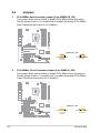
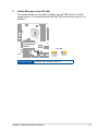
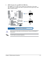
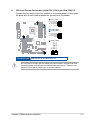
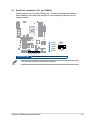
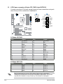
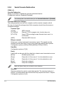
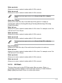
3. COM1/2 Ring/+5V/+12V selection (6-pin COM1_SEL, COM2_SEL)
This jumper allows you to select 5V or 12V depending on your COM device.
Setting Pins
+12V 1-2
+5V 3-4
Ring (Default) 5-6
RI
(Default)
+5V+12V
COM2_SEL
1
2
3
4
5
6
B
COM1_SEL
A
B
A
Connector type HEADER 2x3p, 2.54mm pitch, S/T

Q670EA-IM-A
2-12
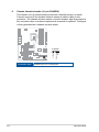
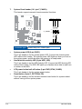
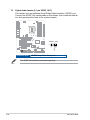
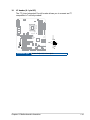
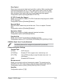
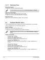
4. AT/ATX mode selection (3-pin AT_ATX_SEL)
In ATX mode (default), you will need to manually press the power button to
turn on the system power. In AT mode, the board will automatically turn on
when system power is connected.
Connector type HEADER 1x3p, 2.54mm pitch, S/T
21 2 3
ATX mode
(Default)
AT mode
AT_ATX_SEL
Pins Description
1-2 (Default) ATX mode
2-3 AT mode
La pagina si sta caricando...
La pagina si sta caricando...
La pagina si sta caricando...
La pagina si sta caricando...
La pagina si sta caricando...
La pagina si sta caricando...
La pagina si sta caricando...
La pagina si sta caricando...
La pagina si sta caricando...
La pagina si sta caricando...
La pagina si sta caricando...
La pagina si sta caricando...
La pagina si sta caricando...
La pagina si sta caricando...
La pagina si sta caricando...
La pagina si sta caricando...
La pagina si sta caricando...
La pagina si sta caricando...
La pagina si sta caricando...
La pagina si sta caricando...
La pagina si sta caricando...
La pagina si sta caricando...
La pagina si sta caricando...
La pagina si sta caricando...
La pagina si sta caricando...
La pagina si sta caricando...
La pagina si sta caricando...
La pagina si sta caricando...
La pagina si sta caricando...
La pagina si sta caricando...
La pagina si sta caricando...
La pagina si sta caricando...
La pagina si sta caricando...
La pagina si sta caricando...
La pagina si sta caricando...
La pagina si sta caricando...
La pagina si sta caricando...
La pagina si sta caricando...
La pagina si sta caricando...
La pagina si sta caricando...
La pagina si sta caricando...
La pagina si sta caricando...
La pagina si sta caricando...
La pagina si sta caricando...
La pagina si sta caricando...
La pagina si sta caricando...
La pagina si sta caricando...
La pagina si sta caricando...
-
 1
1
-
 2
2
-
 3
3
-
 4
4
-
 5
5
-
 6
6
-
 7
7
-
 8
8
-
 9
9
-
 10
10
-
 11
11
-
 12
12
-
 13
13
-
 14
14
-
 15
15
-
 16
16
-
 17
17
-
 18
18
-
 19
19
-
 20
20
-
 21
21
-
 22
22
-
 23
23
-
 24
24
-
 25
25
-
 26
26
-
 27
27
-
 28
28
-
 29
29
-
 30
30
-
 31
31
-
 32
32
-
 33
33
-
 34
34
-
 35
35
-
 36
36
-
 37
37
-
 38
38
-
 39
39
-
 40
40
-
 41
41
-
 42
42
-
 43
43
-
 44
44
-
 45
45
-
 46
46
-
 47
47
-
 48
48
-
 49
49
-
 50
50
-
 51
51
-
 52
52
-
 53
53
-
 54
54
-
 55
55
-
 56
56
-
 57
57
-
 58
58
-
 59
59
-
 60
60
-
 61
61
-
 62
62
-
 63
63
-
 64
64
-
 65
65
-
 66
66
-
 67
67
-
 68
68


Asus Q670EA-IM-A Manuale del proprietario
- Categoria
- Schede madri
- Tipo
- Manuale del proprietario
in altre lingue
- English: Asus Q670EA-IM-A Owner's manual
Documenti correlati
-
Asus R680EA-IM-A Manuale utente
-
-
-
-
-
-
-
-
Asus PRIME B760M-A-CSM Manuale utente
-