Amermec Omnia HL PC Scheda dati
- Categoria
- Filtri dell'aria
- Tipo
- Scheda dati
La pagina sta caricando ...
La pagina sta caricando ...

3
II
II
NN
NN
DD
DD
II
II
CC
CC
EE
EE
••
••
CC
CC
OO
OO
NN
NN
TT
TT
EE
EE
NN
NN
TT
TT
SS
SS
INFORMAZIONI GENERALI
•
GENERAL INFORMATION
4
CARATTERISTICHE
•
FEATURES
Descrizione dell’unità • Description
Componenti principali • Main description 6
Versioni disponibili • Versions available
Descrizione dei componenti • Component description 7
Accessori • Accessories 12
Tabella di compatibilità degli accessori • Accessories compatibility table
Criteri di scelta • Selection 13
Dati tecnici • Technical data 14
Limiti di funzionamento • Operating limits 15
Potenza frigorifera resa • Delivered cooling capacity 16
Potenza termica resa • Heating power 24
Perdite di carico batteria • Pressure drop coil 26
Livelli di potenza sonora • Sound power level
Livelli di pressione sonora • Sound pressure level 27
Imballo • Packing
Installazione dell’unità • Installation 28
Collegamenti elettrici • Electrical connections
Rotazione della batteria • Coil rotation 29
Configurazione Dip-Switch • Dip-Switch configuration 30
Autotest • Autotest function 31
Dati dimensionali • Dimensions 32
Schemi di montaggio • Installation diagrams 34
Dati accessori • Accessories data 35
Schemi elettrici • Wiring diagrams 39
Trasporto • Carriage
Simboli di sicurezza • Safety symbol 41
Problemi e soluzioni • Problem and remedy 42
Servizio Assistenza Tecnica Italia 43

4
II
II
NN
NN
FF
FF
OO
OO
RR
RR
MM
MM
AA
AA
ZZ
ZZ
II
II
OO
OO
NN
NN
II
II
GG
GG
EE
EE
NN
NN
EE
EE
RR
RR
AA
AA
LL
LL
II
II
••
••
GG
GG
EE
EE
NN
NN
EE
EE
RR
RR
AA
AA
LL
LL
II
II
NN
NN
FF
FF
OO
OO
RR
RR
MM
MM
AA
AA
TT
TT
II
II
OO
OO
NN
NN
AERMEC S.p.A. partecipa al Programma di Certificazione
EUROVENT. I prodotti interessati figurano nella Guida
EUROVENT dei Prodotti Certificati.
AERMEC S.p.A. partecipe au Programme de Cerification
EUROVENT. Les produits figurent dans l’Annuaire EURO-
VENT des Produits Certifiés.
AERMEC S.p.A. is partecipating in the EUROVENT
Certification Program. Products are as listed in the EURO-
VENT Directory of Certified Products.
AERMEC S.p.A. is am Zertifikations - programm EUROVENT
beteiligt. Die entsprechend gekennzeichneten Produkte sind
im EUROVENT - Jahrbuch aufgefürt.
AERMEC S.p.A.
I-37040 Bevilacqua (VR) Italia – Via Roma, 44
Tel. (+39) 0442 633111
Telefax (+39) 0442 93730 – (+39) 0442 93566
www.aermec.com - [email protected]
Bevilacqua, 1/1/2003 La Direzione Commerciale - Sales and Marketing Director
LUIGI ZUCCHI
Omnia HL
DICHIARAZIONE DI CONFORMITÀ
Noi, firmatari della presente, dichiariamo sotto la nostra
esclusiva responsabilità, che la macchina in oggetto è
conforme a quanto prescritto dalle seguenti Direttive:
- Direttiva macchine 89/392 CEE e modifiche 91/368 CEE -
93/44 CEE - 93/68 CEE;
- Direttiva bassa tensione 73/23 CEE;
- Direttiva compatibilità elettromagnetica EMC 89/336 CEE.
DECLARATION OF CONFORMITY
We declare under our own responsability that the above
equipment complies with provisions of the following
Standards:
- Equipment Standard 89/392 CEE and amandments
91/368 CEE - 93/44 EEC - 93/68 EEC;
- Low voltage Standard 73/23 EEC;
- Electromagnetic compatibility Standard EMC 89/336 EEC.
CERTIFICAT DE CONFORMITE
Nous, signataires de la présente, certifions sous notre propre
responsabilité, que l’appareil en objet est conforme aux sui-
vantes Directives:
- Directive appareil 89/392 EEC e modifications 91/368 EEC -
93/44 EEC - 93/68 EEC;
- Directive basse tension 73/23 EEC;
- Direttiva compatibilità elettromagnetica EMC 89/336 EEC.
KONFORMITÄTSERKLÄRUNG
Wir, Unterzeichner dieser Bescheinigung, bestätigen, daß
diese Geräte den Vorschriften:
- Vorschrift Geräte 89/392 EWG und entersprechende
ergänzungen 91/368 EWG - 93/44 EWG - 93/68 EWG;
- Niederspannung - Vorschrift 73/23 EWG;
- Funkentstörung - Vorschrift EMC 89/336 EWG.

5
II
II
NN
NN
FF
FF
OO
OO
RR
RR
MM
MM
AA
AA
ZZ
ZZ
II
II
OO
OO
NN
NN
II
II
GG
GG
EE
EE
NN
NN
EE
EE
RR
RR
AA
AA
LL
LL
II
II
••
••
GG
GG
EE
EE
NN
NN
EE
EE
RR
RR
AA
AA
LL
LL
II
II
NN
NN
FF
FF
OO
OO
RR
RR
MM
MM
AA
AA
TT
TT
II
II
OO
OO
NN
NN
OSSERVAZIONI
Questo è uno dei 3 manuali che descrivono la macchina
qui rappresentata. I capitoli descritti nella tabella sottoripor-
tata, sono presenti o assenti a seconda del tipo di manuale.
MANUALI
Tecnico ed Uso *Uso ed
Installazione Installazione
Informazioni generali x x
Caratteristiche: x x x
Descrizione della macchina
versioni, accessori x
Caratteristiche tecniche: x
Dati tecnici x
Dati accessori x
Schemi elettrici x x
Misure di sicurezza: x x x
Precauzioni generali x x x
Installazione: x x
Trasporto x x
Installazione unità x x
Procedure per la messa
in funzione x x x
Uso x x
Manutenzione ordinaria x x x
Individuazione guasti x x x
*= Fornito con la macchina.
Conservare i manuali in luogo asciutto, per evitare il dete-
rioramento, per almeno 10 anni per eventuali riferimenti
futuri.
Leggere attentamente e completamente tutte le informa-
zioni contenute in questo manuale. Prestare particolar-
mente attenzione alle norme d’uso accompagnate dalle
scritte “PERICOLO” o “ATTENZIONE” in quanto, se non
osservate, possono causare danno alla macchina e/o a per-
sone e cose.
ATTENZIONE: i collegamenti elettrici, l'installazione
dei ventilconvettori e dei loro accessori devono essere ese-
guiti solo da soggetti in possesso dei requisiti tecnico-pro-
fessionali di abilitazione all'installazione, alla trasformazio-
ne, all'ampliamento e alla manutenzione degli impianti ed
in grado di verificare gli stessi ai fini della sicurezza e della
funzionalità (in questo manuale saranno indicati con il ter-
mine generico “personale provvisto di specifica competen-
za tecnica”).
In particolare per i collegamenti elettrici si richiedono le
verifiche relative a :
- Misura della resistenza di isolamento dell'impianto elet-
trico.
- Prova della continuità dei conduttori di protezione.
Per anomalie non contemplate da questo manuale, interpel-
lare tempestivamente il Servizio Assistenza di zona.
AERMEC S.p.A. declina ogni responsabilità per qualsiasi
danno dovuto ad un uso improprio della macchina, ad una
lettura parziale o superficiale delle informazioni contenute
in questo manuale.
Il numero di pagine di questo manuale è: 44.
REMARKS
This is one of a set of 3 manuals that describe this machine.
The chapters described in the table below are only included
if relevant to the specific manual.
MANUALS
Technical and Use *Use and
Installation Installation
General information x x
Characteristics: x x x
Machine description with
versions, accessories x
Technical characteristics: x
Technical data x
Accessory data x
Wiring diagrams x x
Safety measures: x x x
General safety practices x x x
Installation: x x
Transport x x
Unit installation x x
Start-up procedures x x x
Use x x
Routine maintenance x x x
Fault-finding x x x
*= Supplied with the machine.
Store the manuals in a dry location to avoid deterioration, as
they must be kept for at least 10 years for any future referen-
ce.
All the information in this manual must be carefully read
and understood. Pay particular attention to the operating
standards with “DANGER” or “WARNING” signals as their
disrespect can cause damage to the machine and/or per-
sons or objects.
WARNING: check that the power supply is disconnec-
ted before performing operations on the unit.
WARNING: wiring connections installation of the fancoil
and relevant accessories should be performed by a techni-
cian who has the necessary technical and professional
expertise to install, modify, extend and maintain plants and
who is able to check the plants for the purposes of safety
and correct operation (In this manual authorised personnel
are referred to with the generic term "personnel with the
necessary technical skills").
In the specific case of electrical connections, the following
must be checked:
- Measurement of the isolation resistance on the electrical
system.
- Testing of the continuity of protection conductors.
If any malfunctions are not included in this manual, contact
the local Aftersales Service immediately.
AERMEC S.p.A. declines all responsibility for any damage
whatsoever caused by improper use of the machine, and a
partial or superficial acquaintance with the information con-
tained in this manual.
This manual has 44 pages.

6
CC
CC
AA
AA
RR
RR
AA
AA
TT
TT
TT
TT
EE
EE
RR
RR
II
II
SS
SS
TT
TT
II
II
CC
CC
HH
HH
EE
EE
••
••
FF
FF
EE
EE
AA
AA
TT
TT
UU
UU
RR
RR
EE
EE
SS
SS
1 Pannello di comando (HL C) • Control panel (HL C)
2 Batteria di scambio termico • Heat exchanger
3 Filtro aria • Air cleaner
4 Mobile di copertura • Cabinet
5 Motore ventilatore • Fan motor
6 Ventilatore • Fan
7 Struttura portante • Bearing structure
8 Scarico condensa • Condensate discharge
9 Collegamenti idraulici • Water connections
10 Testata con alette orientabili • Went with adjustable slats
11 Zoccoli (accessorio ZH) • Mounting feets (ZH accessory)
OMNIA HL-C
COMPONENTI PRINCIPALI • MAIN DESCRIPTION
DESCRIZIONE DELL’UNITÀ
Il ventilconvettore OMNIA HL (High Line) è caratterizzato
dal suo design esclusivo opera dello Studio Giugiaro
Design, ma concentra anche elevate caratteristiche tecnolo-
giche che ne fanno il mezzo ideale di climatizzazione per
ogni ambiente.
Il ventilconvettore OMNIA HL è disponibile in due colo-
razioni, chiara con mobile in colore bianco RAL9018 e con
mobile in colore grigio metallizzato FIAT656, la testata e gli
zoccoli sono per entrambi di colore grigio RAL7031.
L’erogazione di aria climatizzata è immediata e distribuita
in tutto il locale; OMNIA HL genera calore se inserito in un
impianto termico con caldaia o pompa di calore ma può
essere usato anche nei mesi estivi come condizionatore se
l’impianto termico è dotato di un refrigeratore d’acqua.
La qualità dell’aria trattata è garantita da uno speciale fil-
tro precaricato elettrostaticamente che assorbe e trattiene le
polveri in sospensione, a ventilconvettore spento l’aletta
chiusa impedisce alla polvere e a corpi estranei di penetrare
all’interno. La possibilità di rimuovere la bacinella e le
coclee dei ventilatori ispezionabili (eseguibile solo da per-
sonale provvisto di specifica competenza tecnica), consente
di eseguire una pulizia accurata delle parti interne, condi-
zione necessaria per installazioni in luoghi molto affollati o
che richiedono uno standard elevato di igiene.
La silenziosità del nuovo gruppo di ventilazione centrifu-
go è tale che alla normale velocità di utilizzo, non si perce-
pisce quando l’OMNIA HL entra in funzione.
Il ventilconvettore OMNIA HL è concepito per poter soddi-
sfare ogni esigenza di impianto, grazie anche alla ricca dota-
zione di accessori e alla facilità di installazione che può esse-
re sia orizzontale sia verticale, con attacchi idraulici reversi-
bili in fase di installazione e pannello comandi a distanza.
Pieno rispetto delle norme antinfortunistiche.
La manutenzione ordinaria è ridotta alla pulizia periodica
del filtro dell’aria.
UNIT DESCRIPTION
The OMNIA HL (High Line) fancoil, with its characteristic
design by Studio Giugiaro, offers an array of technical featu-
res that make it the ideal climate-control unit for all types of
applications.
The OMNIA HL fan coil is available in two colours, a light
version with a RAL9018 white body and a darker version
with a FIAT656 metallic grey body. The air distribution head
and the skirts are in RAL7031 grey on both versions.
Treated air is immediately delivered to the entire room;
the OMNIA HL produces warm air when fitted to a heating
system with boiler or heat pump, but can also be used
during the summer season as an air-conditioning unit (if the
main system is also equipped with a water chiller).
The quality of processed air is guaranteed by a special
electrostatically pre-charged filter that absorbs and traps
suspended dust particles (when the unit is off, a closed lou-
ver prevents dust and other foreign particles from entering
the unit interior). The removable drip tray and fan volute
ensure thorough cleaning of the unit (In this manual authori-
sed personnel are referred to with the generic term "person-
nel with the necessary technical skills"), essential for instal-
lations in venues subject to crowding or in those with spe-
cial hygiene requirements.
The new centrifugal fan assembly is so quiet that during
standard operation it's virtually impossible to hear when the
OMNIA HL starts up.
With its large range of accessories, easily installed either
vertically or horizontally, water connections can be reversed
as required during installation and remote control panel, the
OMNIA HL fancoil is designed to satisfy all installation
types.
Full compliance with safety regulations.
Routine maintenance is limited to periodic cleaning of the
air filter .
11
1
6
5
4
3
2
9
8
7
10

7
CC
CC
AA
AA
RR
RR
AA
AA
TT
TT
TT
TT
EE
EE
RR
RR
II
II
SS
SS
TT
TT
II
II
CC
CC
HH
HH
EE
EE
••
••
FF
FF
EE
EE
AA
AA
TT
TT
UU
UU
RR
RR
EE
EE
SS
SS
VERSIONI DISPONIBILI
I ventilconvettori della serie OMNIA HL sono disponibili in
4 grandezze e 6 versioni:
Grandezze:
OMNIA 10
OMNIA 15
OMNIA 25
OMNIA 35
Versioni:
HL (mobile colore bianco RAL9018 con commutatore).
HL M (mobile colore grigio metallizzato FIAT656 con
commutatore).
HL C (mobile colore bianco RAL9018 con termostato
elettronico a bordo).
HL CM (mobile colore grigio metallizzato FIAT656 con ter-
mostato elettronico a bordo).
HL S (mobile colore bianco RAL9018 senza comandi a
bordo, per istallazioni con pannello comandi
opzionale esterno, particolarmente indicato per le
installazioni a soffitto).
HL SM (mobile colore grigio metallizzato FIAT656 senza
comandi a bordo, per istallazioni con pannello
comandi opzionale esterno, particolarmente indi-
cato per installazioni a soffitto).
La testata e gli zoccoli sono sempre di colore grigio
RAL7031.
DESCRIZIONE DEI COMPONENTI
1 PANNELLO DI COMANDO
Il pannello comandi (nelle versioni che ne sono dotate) è
alloggiato nella testata del ventilconvettore, protetto da uno
sportellino.
È disponibile anche una versione (HL S - HL SM) particolar-
mente indicata per installazioni a soffitto, senza pannello
comandi, predisposta per l’utilizzo di pannelli comandi
esterni.
I pannelli comandi a bordo dei ventilconvettori OMNIA HL
non consentono il controllo della valvola.
Commutatore manuale (versioni HL - HL M):
serve per la messa in funzione e la selezione
delle velocità del ventilatore.
Termostato elettronico (versioni HL C - HL CM):
I ventilconvettori OMNIA HL C ed HL CM sono
forniti pronti a funzionare in configurazione stan-
dard, ma consentono all’installatore di adeguarli
alle necessità specifiche dell’impianto con acces-
sori dedicati e personalizzando le funzioni agen-
do sui Dip-Switch interni (vedi IMPOSTAZIONI
DIP-SWITCH).
La risposta ai comandi è immediata, tranne casi particolari.
Tipologie d’impianto
I ventilconvettori della serie OMNIA HL sono progettati per
impianti a 2 tubi e sono predisposti per la motorizzazione
della aletta.
Ventilazione
La ventilazione è consentita solo con l’aletta aperta, nei
modelli senza aletta motorizzata è necessario aprirla
manualmente.
La ventilazione a tre velocità può essere comandata sia
manualmente con il selettore (A) in posizione V1, V2 e V3
(il ventilatore è utilizzato con cicli di acceso-spento sulla
velocità selezionata), oppure automaticamente con selettore
VERSIONS AVAILABLE
OMNIA HL fancoils are available in 4 sizes and 6 versions:
Sizes:
OMNIA 10
OMNIA 15
OMNIA 25
OMNIA 35
Versions:
HL (RAL9018 white body with switch).
HL M (FIAT656 metallic grey body with switch).
HL C (RAL9018 white body with on-board electronic
thermostat).
HL CM (FIAT656 metallic grey body with electronic ther-
mostat on board).
HL S (RAL9018 white body with no on-board controls,
for installations using the optional remote control
panel, specially suitable for ceiling mounting).
HL SM (FIAT656 metallic grey body with no on-board
controls, for installations using the optional remote
control panel, specially suitable for ceiling moun-
ting).
The air distribution head and the skirts are always in
RAL7031 grey.
DESCRIPTION OF PARTS
1 CONTROL PANEL
The on-board control panel (in versions with on-board con-
trol panels) is installed under an access door in the head of
the fan coil.
Special versions (HL S - HL SM) are available for ceiling
installation, with no on-board control panel, but with provi-
sion for use of a remote control panel.
The on-board control panels on OMNIA HL fan coils are not
capable of controlling shut-off valves.
Manual switch (versions HL - HL M)
This switch serves to switch the fan coil on and
select fan speed.
Electronic thermostat (HL C - HL CM versions):
OMNIA HL C and HL CM fancoils are delivered
ready to operate in standard configuration, thou-
gh can be adjusted by the installation technician
to specific requirements by means of dedicated
accessories and configuration of functions at the
internal dipswitches (see DIPSWITCH CONFI-
GURATION).
Response to controls is immediate, except in special cases.
Installation types
OMNIA HL series fan coils are designed for two pipe instal-
lations. They also have provisions for the installation of grill
fin drive motors.
Fan functioning (ventilation)
The fans only function with the grill fins open. On models
with no grill fin drive motor, the grill fins must be opened
manually.
The three speed fans can be controlled manually by turning
switch (A) to position V1, V2 or V3. (The fans operate in on-
off cycles at the selected speed). Alternatively, they can be
controlled automatically by turning the switch to the AUTO
A
A B
DC

8
CC
CC
AA
AA
RR
RR
AA
AA
TT
TT
TT
TT
EE
EE
RR
RR
II
II
SS
SS
TT
TT
II
II
CC
CC
HH
HH
EE
EE
••
••
FF
FF
EE
EE
AA
AA
TT
TT
UU
UU
RR
RR
EE
EE
SS
SS
in posizione AUTO (la velocità del ventilatore è gestita dal
termostato in funzione delle condizioni ambientali e dalle
impostazioni dei Dip Switch).
CONTROLLO TERMOSTATICO CON POTENZA MODULATA:
questa impostazione (Dip 1 in posizione OFF), consente di
mantenere in ambiente la temperatura desiderata modulan-
do la potenza erogata dal terminale effettuando dei cicli di
commutazione del ventilatore con Duty Cycle variabile.
Vengono utilizzati 12 diversi livelli di potenza nel modo
Freddo e 12 nel modo Caldo se si imposta la Banda
Normale (Dip.2 in posizione OFF), oppure 12 diversi livelli
di potenza nel modo Freddo e 16 nel Caldo se si imposta la
Banda Estesa (Dip.2 in posizione ON).
I rettangoli (V1, V2 e V3) indicati nelle figure, indicano i
campi di modulazione della potenza:
V1, indica che la potenza viene modulata tramite cicli del
tipo V1-OFF (velocità minima e spento), con periodo fisso e
variando la durata della fase V1 rispetto OFF.
V2, indica che la potenza viene modulata tramite cicli del
tipo V2-V1 (velocità media e velocità minima), variando la
durata della fase V2 rispetto alla fase V1.
V3, indica che la potenza viene modulata tramite cicli del
tipo V3-V2 (velocità massima e velocità media), variando la
durata della fase V3 rispetto alla fase V2.
position. (In this case fan speed is controlled by the thermostat
according to ambient temperature and DIP-switch settings.).
MODULATED POWER THERMOSTATIC CONTROL
In this setting (DIP-switch 1 set OFF), the set room tempera-
ture is maintained by commutating the fans on and off with
variable duty cycles to modulate the power delivered by the
unit.
12 different power levels are used in summer mode and 12
in winter mode when normal band functioning is selected
(DIP-switch 2 set OFF). 12 different power levels are used
in summer mode and 16 in winter mode when extended
band functioning is selected (DIP-switch 2 set ON).
The rectangles (V1, V2 and V3) in the figures show the
power modulation ranges.
With fan speed V1 selected, power is modulated by means
of fixed duration V1-OFF cycles (minimum speed and off) in
which V1 time is varied with respect to OFF time.
With fan speed V2 selected, power is modulated by V2-V1
cycles (medium and minimum speed) in which V2 time is
varied with respect to V1 time.
With fan speed V3 selected, power is modulated by V3-V2
cycles (maximum and medium speed) in which V3 time is
varied with respect to V2 time.
Caldo
Heating
Freddo
Cooling
Ventilazione
Fan ON
Ventilazione
Fan ON
Aletta
Fin
Aletta
Fin
0,9
-2,4
V1
V2
V3
-3,6
-4,8
3,6
2,7
1,8
-0,4
-0,9
0,4
V1
V2
V3
Caldo
Heating
Freddo
Cooling
Ventilazione
Fan ON
Ventilazione
Fan ON
Aletta
Fin
Aletta
Fin
0,9
-1,8
V1
V2
V3
-2,7
-3,6
3,6
2,7
1,8
-0,4
-0,9
0,4
V1
V2
V3
Controllo termostatico con Potenza Modulata Banda Normale
Normal band modulated power thermostatic control
Controllo termostatico con Potenza Modulata Banda Estesa
Extended band modulated power thermostatic control

9
CC
CC
AA
AA
RR
RR
AA
AA
TT
TT
TT
TT
EE
EE
RR
RR
II
II
SS
SS
TT
TT
II
II
CC
CC
HH
HH
EE
EE
••
••
FF
FF
EE
EE
AA
AA
TT
TT
UU
UU
RR
RR
EE
EE
SS
SS
CONTROLLO TERMOSTATICO A 3 LIVELLI:
questa impostazione (Dip 1 in posizione ON), consente di
mantenere in ambiente la temperatura desiderata con il
controllo a tre livelli.
Cambio stagione
Il termostato cambia modalità di funzionamento (riscalda-
mento o raffrescamento) automaticamente.
Il cambio stagione avviene in base alla temperatura
dell’acqua rilevata nell’impianto:
- 35°C a Caldo Normale oppure 31°C a Caldo Ridotto,
- 22°C a Freddo Normale oppure 25°C a Freddo Ridotto,
(sono configurabili tramite i Dip-Switch).
Controlli sulla temperatura dell’acqua
Il termostato abilita la ventilazione solamente se la tempera-
tura dell’acqua è idonea al modo Caldo o Freddo.
Le soglie di abilitazione alla ventilazione sono:
- 39°C a Caldo Normale oppure 35°C a Caldo Ridotto,
3 LEVEL THERMOSTATIC CONTROL
In this setting (DIP-switch1 set ON) all the three power
levels are used to maintain the room at the set temperature.
Season changeover
The thermostat automatically changes function mode (hea-
ting in winter mode and cooling in summer mode).
Season changes are triggered by the temperature of the
water in the system:
-35°C in normal winter mode or 31°C in economy winter
mode,
-22°C in normal summer mode or 25°C in economy sum-
mer mode.
(Settings are configurable by means of the DIP-switches.).
Water temperature controls
The thermostat permits fan operation only if water tempera-
ture is suitable for the active mode (winter or summer).
The fan enabling thresholds are as follows:
- 39°C in normal winter mode or 35°C in economy winter mode,
22°C
39°C35°C25°C
Caldo
Heating
Freddo
Cooling
Ventilazione
disabilitata
Fan off
Dip.6 ON
Freddo ridotto
Reduced Cooling
Dip.5 OFF
Caldo normale
Normal Heating
Dip.5 ON
Caldo ridotto
Reduced Heating
Dip.6 ON
Freddo ridotto
Reduced Cooling
22°C
35°C31°C25°C
Caldo
Heating
Freddo
Cooling
Ventilazione
disabilitata
Fan off
17°C
39°C35°C22°C
17°C
35°C31°C22°C
Caldo
Heating
Freddo
Cooling
Caldo
Heating
Freddo
Cooling
Ventilazione
disabilitata
Fan off
Ventilazione
disabilitata
Fan off
Dip.6 OFF
Freddo normale
Normal Cooling
Dip.5 ON
Caldo ridotto
Reduced Heating
Dip.6 OFF
Freddo normale
Normal Cooling
Dip.5 OFF
Caldo normale
Normal Heating
Caldo
Heating
Freddo
Cooling
Ventilazione
Fan ON
Ventilazione
Fan ON
Aletta
Fin
0,9
-0,3
V1
V2
V3
-4,8
3,6
-0,4
-0,9
0,4
V1
V2
V3
Aletta
Fin
2,1
-2,7
0,3
Aletta
Fin
V1
V2
V3
-2,1
-3,6
0,4
-3,0
-1,5
Caldo
Heating
Freddo
Cooling
Ventilazione
Fan ON
Ventilazione
Fan ON
Aletta
Fin
0,9
3,6
2,1
-0,4
-0,9
V1
V2
V3
-0,3
0,3
3,0
1,5
3,0
1,5
-4,2
-2,1
Controllo termostatico a 3 livelli Banda Normale
Three level normal band thermostatic control
Controllo termostatico a 3 livelli Modulata Banda Estesa
Three level extended band thermostatic control

10
CC
CC
AA
AA
RR
RR
AA
AA
TT
TT
TT
TT
EE
EE
RR
RR
II
II
SS
SS
TT
TT
II
II
CC
CC
HH
HH
EE
EE
••
••
FF
FF
EE
EE
AA
AA
TT
TT
UU
UU
RR
RR
EE
EE
SS
SS
- 17°C Freddo Normale oppure 22°C a Freddo Ridotto,
(sono configurabili tramite i Dip-Switch).
Il pannello comandi segnala la situazione in cui la tempera-
tura dell’acqua non sia adeguata al modo di funzionamento
impostato, tramite il lampeggio alternato sul led C del colo-
re fucsia con i colori rosso o blu relativi al modo attivo.
Correzione sonda
É possibile selezionare la correzione da applicare alla lettu-
ra della sonda ambiente nel funzionamento a caldo, lo
scopo è di correggere l’effetto del surriscaldamento che vi è
all’interno del ventilconvettore.
Il valore di Correzione Fissa è -3,9°C (Dip 4 in posizione ON).
Il valore di Correzione Dinamica (Dip 4 in posizione OFF)
dipende dallo stato del ventilconvettore e può raggiunge-
re un valore massimo di -4,5°C.
Frost Protection (protezione antigelo)
La protezione antigelo prevede di controllare che la tempe-
ratura ambiente non scenda mai a valori di gelo, anche
quando il ventilconvettore è spento ed il selettore (A) è in
OFF.
Nel caso in cui la temperatura scenda sotto i 7°C il termo-
stato avvia il ventilconvettore nel funzionamento a caldo
con set a 12°C e ventilazione in AUTO, sempre che la tem-
peratura dell’acqua lo consenta, che il ventilconvettore sia
alimentato e che, per i modelli con aletta manuale, l’aletta
di mandata sia in posizione aperta.
Esce dal modo antigelo quando la temperatura supera i 9°C.
Modo Emergenza
In caso di avaria delle sonde il termostato elettronico si
comporta nel seguente modo:
- avaria sonda ambiente SA, il termostato entra in modalità
“Emergenza”, indicata dal lampeggiare del led (D) bianco.
Con selettore (A) in posizione OFF il ventilatore è spento.
Con selettore (A) in posizione AUTO, V1, V2 e V3 il venti-
latore esegue dei cicli di acceso - spento; in questa situazio-
ne la potenza erogata dal terminale viene comandata
manualmente tramite il selettore di temperatura (B), ruotan-
do verso destra la durata del ciclo di Acceso aumenta; ruo-
tando verso sinistra la durata diminuisce.
- avaria sonda acqua SW, il termostato entra in modalità
“Cambio stagione da set”.
La ventilazione è sempre abilitata.
Il cambio stagione avviene in base alle seguenti regole:
a) se il termostato è in modo Freddo e la richiesta del ter-
mostato è di 5°C inferiore al set impostato, allora automati-
camente il termostato richiede il modo Caldo.
b) se il termostato è in modo Caldo e la richiesta del termo-
stato è di 5°C superiore al set impostato, allora automatica-
mente il termostato richiede il modo Freddo.
2 BATTERIA DI SCAMBIO TERMICO
Batteria a 2 ranghi in tubo di rame e alettatura in alluminio
bloccata mediante espansione meccanica dei tubi. I collet-
tori sono corredati di attacchi femmina e sfiati aria nella
parte alta della batteria.
La batteria può essere ruotata in cantiere.
3 FILTRO DELL’ARIA PRECARICATO ELETTROSTATICAMENTE
- 17°C in normal summer mode or 22°C in economy sum-
mer mode.
(Settings are configurable by means of the DIP-switch swit-
ches.)
If water temperature is not suitable for the set functioning
mode, the control panel alternately flashes LED C in violet
and red or blue depending on the mode active at the time.
Probe correction
In winter mode, you can select the most suitable correction
factor to apply to the room temperature probe reading, to
allow for heat inside the fan coil itself.
The fixed correction value is -3,9°C (DIP-switch 4 set ON).
The dynamic correction value (DIP-switch 4 set OFF)
depends on the status of the fan coil and can reach a maxi-
mum value of -4,5°C.
Frost Protection
This function prevents room temperature from dropping
below an ambient temperature of 7°C (even when the fan-
coil is off and selector switch A is in the OFF position).
In the event that room temperature drops below 7°C, the
thermostat starts up the fancoil in heating mode at a tempe-
rature setting of 12°C and fan operation set to AUTO (if per-
mitted by water temperature, the unit is connected to the
power supply and the louvers are open, in the case of
manual units).
Frost protection mode is deactivated when room temperatu-
re rises above 9°C.
Emergency mode
In the event of fault in the ambient probe, the thermostat
operates as follows:
- ambient probe SA fault, the thermostat sets to Emergency
mode (indicated by the flashing of white LED D).
- with selector switch (A) in OFF position: fan off;
- with selector switch (A) in AUTO, V1, V2 or V3 position:
the fan performs on-off cycles; in this case, the power sup-
plied by the terminal is controlled manually by means of the
temperature selector switch (B): rotate the switch to right to
increase cycle duration, or to the left to reduce it.
- water probe SW fault, the thermostat sets to "Season
changeover" mode.
- ventilation is constantly enabled.
Season changeover proceeds as follows:
a) when the thermostat is in cooling mode and the thermo-
stat request is 5°C below the setting, the thermostat automa-
tically requests heating mode;
b) when the thermostat is in heating mode and the thermo-
stat request is 5°C higher than the setting, the thermostat
automatically requests cooling mode.
2 HEAT EXCHANGE COIL
The coil is a two row copper pipe coil with aluminium fins
mechanically fitted by expansion of the pipes. The terminals
are fitted with female unions and air bleeders at the top.
The coil can be reversed on site.
3 ELECTROSTATICALLY PRECHARGED AIR FILTER
0,3
0,5
0,7
1,0
2,0
0
0
10
20
30
40
50
Diametro particelle [µm] • Particle diameters [
µ
m]
Efficienza frazionale [%] • Efficiecy
[
%
]
=
Filtro serie HL Aermec
Aermec HL hight efficiency filter
=
Filtro standard per ventilconvettori
Standard filter for fan coil unit

11
CC
CC
AA
AA
RR
RR
AA
AA
TT
TT
TT
TT
EE
EE
RR
RR
II
II
SS
SS
TT
TT
II
II
CC
CC
HH
HH
EE
EE
••
••
FF
FF
EE
EE
AA
AA
TT
TT
UU
UU
RR
RR
EE
EE
SS
SS
Resistenza al fuoco Classe 2 (UL 900).
Facilmente estraibile è fornito a corredo del ventilconvetto-
re in confezione sigillata, da aprire solo al momento
dell’utilizzo.
Il filtro precaricato elettrostaticamente abbina alla normale
filtrazione meccanica dell’aria che passa attraverso il filtro,
anche una attrazione elettrostatica delle polveri che ne
aumenta sensibilmente la filtrazione.
La precarica elettrostatica del filtro si esaurisce dopo 2 anni
dall’apertura della confezione, dopo tale periodo si com-
porterà come un normale filtro. Per questo motivo se ne
consiglia la sostituzione con uno nuovo dopo 2 anni.
Pulire frequentemente, togliere la polvere accumulata con
un aspiratore, l’uso di acqua e detergenti, accelera sensibil-
mente il decadimento della precarica elettrostatica.
4 MOBILE DI COPERTURA
Realizzato in lamiera opportunamente trattata per garantire
alta resistenza alla ruggine e alla corrosione, disponibile in
due colorazioni, chiara con mobile in colore bianco
RAL9018 e con mobile in colore grigio metallizzato
FIAT656.
La testata e gli zoccoli in materiale plastico sono per
entrambi di colore grigio RAL7031.
5 - 6 GRUPPO ELETTROVENTILANTE
È applicato direttamente al telaio ed è costituito da ventila-
tori centrifughi (6) a doppia aspirazione estremamente silen-
ziosi e compatti. Il motore elettrico (5), protetto contro i
sovraccarichi, è a tre velocità con condensatore di marcia
sempre inserito, direttamente accoppiato ai ventilatori ed
ammortizzato con supporti elastici.
Le coclee dei ventilatori sono ispezionabili (eseguibile da
personale provvisto di specifica competenza tecnica), que-
sto consente di eseguire una pulizia accurata delle parti
interne.
7 STRUTTURA PORTANTE
È realizzata in lamiera di adeguato spessore protetta contro
l’ossidazione mediante zincatura, dotata di isolamento ter-
mico a cellula chiusa con Classe 1 di resistenza al fuoco.
Nella parte posteriore ha i fori per il fissaggio a muro del-
l'apparecchio. Per i modelli pensili sono previste, per facili-
tare l’installazione al soffitto, due staffe in dotazione, da
applicare alle fiancate del telaio. Ogni apparecchio è corre-
dato di bacinella raccolta condensa rimovibile per una puli-
zia accurata (eseguibile solo da personale provvisto di spe-
cifica competenza tecnica).
8 SCARICO CONDENSA
Collegamento per la fuoriuscita della condensa prodotta
dall’unità in raffrescamento.
9 COLLEGAMENTI IDRAULICI
I collegamenti, posizionati nella fiancata sinistra, sono ad
attacco femmina. È prevista la possibilità di ruotare la batte-
ria in cantiere.
10 TESTATA CON ALETTA ORIENTABILE
La testata è in materiale plastico di colore RAL7031.
Con l’aletta deflettrice in posizione di completa chiusura,
l’intervento del microinterruttore arresta la ventilazione,
interrompendo qualsiasi ulteriore scambio di calore con
l’ambiente.
La testata alloggia anche il pannello comandi (nelle versioni
che ne sono dotate), protetto da uno sportellino.
Filter fire resistance is Class 2 ( UL 900).
The easy to remove air filter is delivered in sealed packaging
together with the fan coil. The packaging should only be
opened at the moment of installation.
The electrostatically precharged air filter combines normal,
mechanical filtration of the air passing through it with an
electrostatic filtration that attracts dust and significantly
improves performance.
The filter's electrostatic charge lasts for 2 years after the pro-
tective packaging is opened. After this, the filter acts only as
a normal filter. For this reason it is important to replace the
filter with a new one at these intervals.
Clean the filter frequently. Use a vacuum cleaner to remove
built up dust. Avoid water or detergents if possible since
they greatly accelerate loss of the filter's electrostatic charge.
4 CABINET HOUSING
The fan coil cabinet is manufactured in sheet metal, suitably
treated to ensure excellent rust and corrosion resistance.
The cabinet is available in two colours, a light version with a
RAL9018 white cabinet and a darker version with a FIAT656
metallic grey cabinet.
The air distribution head and the plastic skirts are in
RAL7031 grey on both versions.
5 - 6 THE FAN GROUP
The fan group is fitted directly on the fan coil frame and
comprises a set of extremely silent running and compact
double intake centrifugal fans (6). The three speed electric
motor (5) is protected against overload and features a per-
manently active condenser. The motor is coupled directly to
the fans. Vibration is damped by elastic mountings.
The fan screws (cochleas) can be opened for inspection
and thorough internal cleaning (by personnel with the
necessary technical skills).
7 MAIN FRAME
The frame is made from suitably thick sheet metal and is gal-
vanised to ensure protection against corrosion. The frame
also features closed cell thermal insulation with Class 1 fire
resistance.
The rear of the frame has holes for wall mounting the
appliance. To facilitate ceiling mounting, hung models are
provided with two brackets for fixing to the sides of the
frame. All appliances come complete with a condensation
drip tray that can be easily removed for thorough cleaning
(only by personnel with the necessary technical skills).
8 CONDENSATION DRAIN
This connection permits the condensation that forms inside
the cooling unit to be drained off.
9 WATER CONNECTIONS
The female union water connections are located on the left
hand side panel. The coil can be reversed on site if required.
10 HEAD AND ORIENTABLE GRILL FINS
The head is in RAL7031 coloured plastic.
When the grill fins are fully closed, a switch stops the fans,
thus preventing further transfer of heat between the unit and
the room.
The head also houses the control panel (in versions with
control panel), under a protective door.

12
CC
CC
AA
AA
RR
RR
AA
AA
TT
TT
TT
TT
EE
EE
RR
RR
II
II
SS
SS
TT
TT
II
II
CC
CC
HH
HH
EE
EE
••
••
FF
FF
EE
EE
AA
AA
TT
TT
UU
UU
RR
RR
EE
EE
SS
SS
ACCESSORI
BC10 BACINELLA AUSILIARIA RACCOLTA CONDENSA
PER VENTILCONVETTORI INSTALLATI VERTICALMENTE
In materiale plastico, consente la raccolta della condensa
che si forma durante il funzionamento con acqua fredda,
sulle connessioni idrauliche e sull’eventuale valvola a tre
vie nelle unità installate verticali.
L’accessorio BC10 è abbinabile ai ventilconvettori OMNIA
HL di tutte le grandezze ed in tutte le versioni.
BC20 BACINELLA AUSILIARIA RACCOLTA CONDENSA
PER VENTILCONVETTORI INSTALLATI PENSILI
In materiale plastico, consente la raccolta della condensa
che si forma durante il funzionamento con acqua fredda,
sulle connessioni idrauliche e sull’eventuale valvola a tre
vie nelle unità installate pensili al soffitto.
L’accessorio BC20 è abbinabile ai ventilconvettori OMNIA
HL di tutte le grandezze ed in tutte le versioni.
PX2 PANNELLO COMANDI (Installazione a parete)
Non è possibile l’installazione a bordo macchina.
Pannello comandi da installarsi a parete, costituito da com-
mutatore acceso/spento e da commutatore a tre posizioni
per la selezione della velocità del ventilatore.
Non é possibile l’accoppiamento del pannello con una
sonda della temperatura dell’acqua.
Ogni pannello può controllare un solo ventilconvettore.
Per ulteriori informazioni si rimanda alle istruzioni
dell’accessorio.
PXB PANNELLO COMANDI (Installazione a parete)
Non è possibile l’installazione a bordo macchina.
Il pannello comandi PXB a tre velocità è dotato di un termo-
stato elettronico che comanda l'arresto della ventilazione al
raggiungimento della temperatura ambiente impostata.
La sonda di temperatura ambiente é posizionata all’interno
del termostato.
Non é possibile l’accoppiamento del termostato con una
sonda della temperatura dell’acqua.
Ogni pannello può controllare un solo ventilconvettore.
Per ulteriori informazioni si rimanda alle istruzioni
dell’accessorio.
PXL2E PANNELLO COMANDI MULTIFUNZIONE
Non è possibile l’installazione a bordo macchina.
Pannello comandi per installazione a parete, in impianti a
due tubi, dotato di termostato elettronico multifunzione che
controlla il funzionamento del ventilconvettore in funzione
della modalità impostata, della temperatura ambiente e
della temperatura dell’acqua nel circuito per mantenere
nell’ambiente la temperatura impostata.
Il pannello comandi va utilizzato su impianti a 2 tubi con la
possibilità di collegare la valvola (VCH) di tipo On - Off per
l'intercettazione dell'acqua di alimentazione della batteria.
La sonda di temperatura ambiente é posizionata all’interno
del termostato. Per ulteriori informazioni si rimanda alle
istruzioni dell’accessorio.
VCH KIT VALVOLE A 3 VIE
I pannelli comandi a bordo dei ventilconvettori OMNIA
HL non consentono il controllo della valvola, è necessario
usare un pannello comandi esterno dotato di tale controllo.
Kit completi di raccorderie in rame e valvole a tre vie del tipo
tutto o niente, predisposte per alimentazione a
230 V monofase.
L’accessorio VCH è abbinabile ai ventilconvettori OMNIA
HL di tutte le grandezze.
ZH ZOCCOLI PER MOBILE
In materiale plastico di colore RAL7031, vengono montati
alla base del mobile quando l'apparecchio viene appoggia-
to al pavimento.
L’accessorio ZH è abbinabile ai ventilconvettori OMNIA HL
di tutte le grandezze.
ACCESSORIES
BC10 AUXILIARY CONDENSATION BASIN FOR VERTI-
CALLY MOUNTED FAN COILS
These plastic basins collect the condensation that forms on
the water connections and on the three way valve (if fitted)
when vertically mounted units are operating in summer
mode.
The BC10 condensation basin can be used with all OMNIA
HL fan coil ratings and versions.
BC20 AUXILIARY CONDENSATION BASIN FOR CEILING
MOUNTED FAN COILS
These plastic basins collect the condensation that forms on
the water connections and on the three way valve (if fitted)
when ceiling mounted units are operating in summer mode.
The BC20 condensation basin accessory can be used with
all OMNIA HL fan coil fan coil ratings and versions.
PX2 CONTROL PANEL (for wall mounting)
Cannot be installed on board fan coils.
These control panels are designed for wall mounting installa-
tion. They include an on/off switch and a three position fan
speed switch.
The control panel cannot be used in conjunction with a
water temperature sensor.
These control panels are designed to control just one fan
coil.
See the control panel's own instructions for further details.
PXB CONTROL PANEL (for wall mounting)
Cannot be installed on board fan coils.
PXB three speed control panels are equipped with electronic
thermostats that stop the fans when the set room temperatu-
re is reached.
The room temperature sensor is installed inside the thermo-
stat unit.
The thermostat cannot be used in conjunction with a water
temperature sensor.
These control panels are designed to control just one fan
coil.
See the control panel's own instructions for further details.
PXL2E MULTI-FUNCTION CONTROL PANEL
Cannot be installed on board fan coils.
These wall mounted control panels for two pipe systems
include multi-function electronic thermostats that control
fan coil functions and maintain the set room temperature on
the basis of selected function mode, room temperature and
circuit water temperature readings.
PXL2E control panels are for use with two pipe systems
that can be connected to the (VCH) On - Off valve to shut
off water flow to the coils.
The room temperature sensor is installed inside the thermo-
stat unit.
See the control panel's own instructions for further details.
VCH 3 WAY VALVE KIT
The on-board control panels installed in OMNIA HL fan
coils are not designed to control this valve. A remote con-
trol panel with a control circuit for this type of valve must
therefore be installed instead.
The kit comes complete with all necessary copper unions
and all-or-nothing type three way valves designed for 230 V
single phase power supplies.
The VCH 3-way valve can be used with all OMNIA HL fan
coil ratings.
ZH MOUNTING FEETS
ZH mounting feets come in RAL7031 coloured plastic, and
are designed for installation around the base of floor stan-
ding fan coil bodies.
ZH mounting feets can be used with all OMNIA HL fan coil
ratings.

13
CC
CC
AA
AA
RR
RR
AA
AA
TT
TT
TT
TT
EE
EE
RR
RR
II
II
SS
SS
TT
TT
II
II
CC
CC
HH
HH
EE
EE
••
••
FF
FF
EE
EE
AA
AA
TT
TT
UU
UU
RR
RR
EE
EE
SS
SS
CRITERI DI SCELTA
I ventilconvettori OMNIA HL sono dotati di aspirazione
frontale e si prestano ad installazioni pensili, verticali a
parete e a pavimento con l’impiego degli appositi zoccoli.
Le tabelle da TAV.1 a 4 riportano le rese frigorifere sensibili
e totali alla massima velocità in funzione della temperatura
dell'acqua entrante, del suo salto termico e della temperatu-
ra a bulbo secco e a bulbo umido dell'aria rispettivamente
per resa sensibile e resa totale, le prestazioni alle velocità
media e minima si ottengono applicando i relativi coeffi-
cienti correttivi.
I diagrammi delle tavole da TAV.5 a 8 riportano la potenza
termica resa alla massima velocità in funzione della portata
d'acqua e della differenza di temperatura tra acqua entrante
e aria entrante per le batterie a 2 ranghi (di serie), per le
velocità inferiori fare riferimento ai relativi coefficienti cor-
rettivi.
Il diagramma di TAV.9 riporta le perdite di carico della bat-
teria in funzione della portata d’acqua alla temperatura
media di 10°C, per acqua circolante a temperature diverse
fare riferimento ai relativi coefficienti correttivi.
Nelle tavole TAV.10 e TAV.11 sono riportati rispettivamen-
te il livello di potenza e di pressione sonora dei ventilcon-
vettori alle varie velocità.
Accessori
Ventilconvettore HL • HL Fancoil
Accessories
Grandezza • Size
Versioni • Versions
10 15 25 35
10 ✔✔✔✔HL - HL M - HL C - HL CM - HL S - HL SM
BC
20 ✔✔✔✔HL - HL M - HL C - HL CM - HL S - HL SM
PX2 ✔✔✔✔HL S - HL SM
PXB ✔✔✔✔HL S - HL SM
PXL2E ✔✔✔✔HL S - HL SM
VCH(*) ✔✔✔✔HL - HL M - HL C - HL CM - HL S - HL SM
ZH ✔✔✔✔HL - HL M - HL C - HL CM - HL S - HL SM
TABELLA DI COMPATIBILITÀ DEGLI ACCESSORI • ACCESSORIES COMPATIBILITY TABLE
(*) = Valvola non gestita dal pannello montato a bordo macchina, richiede un pannello comandi esterno.
(*) = This valve cannot be controlled by on-board control panels, and requires a suitable remote control panel.
SELECTION CRITERIA
Since OMNIA HL fan coils have front aspiration, they are
ideal for ceiling mounting, vertical wall mounting and, with
suitable skirts, floor mounting too.
The tables in TAV. 1 to TAV.4 show sensible and total coo-
ling capacity at maximum fan speed as a function of water
inlet temperature, water heat drop and dry and wet bulb air
temperature for sensible and total cooling capacity respecti-
vely. Performance for medium and minimum fan speeds can
be obtained by applying the relevant correction factors.
The diagrams in TAV. 5 to TAV.8 show the heating capacity
at maximum fan speed as a function of water flow and the
difference in temperature between the water inlet and the
air inlet for two row coils (standard). Performance for
medium and minimum fan speeds can be obtained by
applying the relevant correction factors.
The diagram in TAV. 9 shows the coil's load loss as a func-
tion of water flow at a mean temperature of 10°C.
Performance for other water circuit temperatures can be
obtained by applying the relevant correction factors.
TAV. 10 and TAV.11 show sound power and sound pressu-
re levels respectively at various fan speeds.

14
CC
CC
AA
AA
RR
RR
AA
AA
TT
TT
TT
TT
EE
EE
RR
RR
II
II
SS
SS
TT
TT
II
II
CC
CC
HH
HH
EE
EE
••
••
FF
FF
EE
EE
AA
AA
TT
TT
UU
UU
RR
RR
EE
EE
SS
SS
Mod. 10 15 25 35
❊ Resa termica
max. [W] 2010 2910 4620 5940
Heating capacity
med.
[W]
1460 2120 3830 4870
min. [W]
1060 1540 2890 3530
❊❊
Resa termica (acqua ingresso 50°C) (E)
[W] 1150 1700 2750 3540
Heating capacity (water in 50°C) (E)
❊ Portata acqua • Water flow [l/h] 173 250 397 511
❊
Perdite di carico acqua
[kPa] 1,6 3,7 10,5 7,4
Water pressure drops
❆ Resa frigorifera totale
max. (E) [W] 840 1200 2030 2830
Total cooling capacity
med. [W] 650 950 1780 2310
min. [W] 490 690 1420 1730
❆ Resa frigorifera sensibile
max. (E) [W] 700 990 1640 2040
Sensible cooling capacity
med. [W] 530 750 1370 1790
min. [W] 390 520 1050 1280
❆ Portata acqua • Water flow [l/h] 144 206 349 487
❆
Perdite di carico acqua
[kPa] 1,84 3,40 10,20 8,67
Water pressure drops
Portata d’aria
max. [m
3
/h] 180 240 350 460
Air flow
med. [m
3
/h] 120 160 270 350
min. [m
3
/h] 80 110 190 240
Numero di ventilatori • Fan number 1122
Livello di pressione sonora
max. [dB (A)] 37,5 39,5 39,5 39,5
med. [dB (A)] 28,5 34,5 34,5 32,5
Sound pressure level
min. [dB (A)] 22,5 25,5 26,5 25,5
Livello di potenza sonora
max. (E) [dB (A)] 46,0 48,0 48,0 48,0
Sound power level
med. [dB (A)] 37,0 43,0 43,0 41,0
min. [dB (A)] 31,0 34,0 35,0 34,0
Contenuto acqua • Water content [l] 0,4 0,5 0,8 1,1
Potenza max. motore • Max. motor power (E) [W] 18 32 35 42
Corrente max. assorbita • Max. input current [A] 0,09 0,15 0,18 0,22
Attacchi batteria • Coil connections ø 1/2” 1/2” 1/2” 1/2”
Dimensioni
Altezza • Height [mm] 600 605 615 623
con zoccoli
Larghezza • Width [mm] 640 750 980 1200
Dimensions
with base supports
Profondità • Depth [mm] 187 189 191 198
Altezza zoccoli • Base support height [mm] 93 93 93 93
Peso netto senza zoccoli
[kg] 13,6 14,6 17,6 20,6
Net weight without base supports
Tensione di alimentazione • Power supply = 230 V / 1 N / 50 Hz (± 10 % ).
(E) = Prestazioni certificate Eurovent. • Eurovent certified performance.
DATI TECNICI • TECHNICAL DATA
Le prestazioni sono riferite alle seguenti condizioni:
– tensione di alimentazione 230 V / 1N / 50Hz;
❊ riscaldamento:
ingresso acqua = 70 °C ;
ingresso aria = 20 °C ;
∆t acqua = 10 °C alla massima velocità ventilatore; per
media e minima velocità ventilatore portata acqua come
alla massima velocità;
❊❊riscaldamento:
ingresso aria = 20 °C;
ingresso acqua = 50 °C;
max. velocità ventilatore; portata acqua come in raffredda-
mento;
❆ raffreddamento:
ingresso aria = 27 °C b. s. -19 °C b. u.;
ingresso acqua = 7 °C;
∆t acqua = 5 °C alla massima velocità ventilatore; per
media e minima velocità ventilatore portata acqua come
alla massima velocità;
livello di pressione sonora (ponderato A) misurato in
ambiente con volume di 85 m
3
e tempo di riverbero di
0,5 s.
Performances refer to following conditions:
– power supply 230 V / 1N / 50Hz;
❊
heating:
water in = 70 °C ;
air in = 20 °C ;
∆t water = 10 °C maximum fan speed ; for medium and
minimum fan speed water flow as per maximum speed;
❊❊
heating:
air in = 20 °C ;
water in = 50 °C;
maximum fan speed; water flow as in cooling operation;
❆
cooling:
air in = 27 °C d. b. -19 °C w. b.-
water in = 7 °C ;
∆t water = 5 °C maximum fan speed; for medium and
minimum fan speed water flow as per maximum speed;
sound pressure level (weighted A) measured in room
with 85 m
3
volume and reverberation time of 0.5
seconds.

15
CC
CC
AA
AA
RR
RR
AA
AA
TT
TT
TT
TT
EE
EE
RR
RR
II
II
SS
SS
TT
TT
II
II
CC
CC
HH
HH
EE
EE
••
••
FF
FF
EE
EE
AA
AA
TT
TT
UU
UU
RR
RR
EE
EE
SS
SS
MINIMA TEMPERATURA MEDIA ACQUA
Temperatura a bulbo secco dell’aria ambiente °C
MINIMUM AVERAGE WATER TEMPERATURE
Dry bulb temperature °C
21 23 25 27 29 31
15 333333
Temperatura a bulbo umido
17 333333
dell’aria ambiente °C
19 333333
Wet bulb temperature °C
21 654333
23 -87655
LIMITI DI FUNZIONAMENTO
Massima temperatura ingresso acqua ........................80 °C
Massima pressione d’esercizio....................................8 bar
Minima temperatura media dell’acqua
Per evitare fenomeni di condensazione sulla struttura ester-
na dell’apparecchio con ventilatore in funzione, la tempera-
tura media dell’acqua non deve essere inferiore ai limiti
riportati nella tabella sottostante, che dipendono dalle con-
dizioni termo-igrometriche dell’aria ambiente.
I suddetti limiti si riferiscono al funzionamento con ventila-
tore in moto alla minima velocità.
In caso di prolungata situazione con ventilatore spento e
passaggio di acqua fredda in batteria, è possibile la forma-
zione di condensa all’esterno dell’apparecchio, pertanto si
consiglia l’inserimento dell’accessorio valvola a tre vie .
OPERATING LIMITS
Maximum water inlet temperature..............................80 °C
Maximum working pressure.........................................8 bar
Average minimum water temperature
To prevent the formation of condensation on the exterior of
the unit while the fan is operating, the average water tempe-
rature should not drop beneath the limits shown in the table
below, determined by the ambient conditions.
These limits refer to unit operation with fan at minimum
speed.
Note that condensation may form on the exterior of the unit
if cold water circulates through the coil while the fan is off
for prolonged periods of time, so it is advisable to fit the
additional three-way valve .
Limiti di portata:
Water flow limits:
MOD. 10 15 25 35
Portata minima • Minimum water flow [l/h] 100 100 100 150
Portata massima • Maximum water flow [l/h] 700 700 700 1.050
La pagina sta caricando ...

17
CC
CC
AA
AA
RR
RR
AA
AA
TT
TT
TT
TT
EE
EE
RR
RR
II
II
SS
SS
TT
TT
II
II
CC
CC
HH
HH
EE
EE
••
••
FF
FF
EE
EE
AA
AA
TT
TT
UU
UU
RR
RR
EE
EE
SS
SS
T w [°C]
∆∆
t
Ta b.u. [°C]
Pc Ps Pc Ps Pc Ps Pc Ps Pc Ps Pc Ps
Ta w.b. [°C]
21°C Ta b.s. 23°C Ta b.s. 25°C Ta b.s. 27°C Ta b.s. 29°C Ta b.s. 30°C Ta b.s.
15 -- -- -- -- -- --
17 239 226 329 312 464 439 582 552 695 658 804 761
3 19 295 200 363 314 473 441 584 553 697 660 806 763
21 - - 731 340 722 439 737 545 777 654 836 764
A 23 - - - - 1123 451 1115 549 1109 650 1103 750
15 -- -- -- -- -- --
17 -- -- -- -- -- --
13 5 19 192 154 266 230 350 332 435 412 521 494 651 617
21 - - 341 206 384 311 446 409 522 495 653 618
23 - - - - 599 278 603 380 660 489 756 619
15 -- -- -- -- -- --
17 -- -- -- -- -- --
719------------
21 - - 226 162 299 265 374 354 458 434 543 514
23 - - - - 387 212 429 317 487 417 554 512
15 -- -- -- -- -- --
17 -- -- -- -- -- --
3 19 161 141 241 228 341 323 471 447 588 557 699 662
21 - - 311 197 405 324 496 445 589 558 701 664
23 - - - - 806 344 802 445 802 546 830 653
15 -- -- -- -- -- --
17 -- -- -- -- -- --
15519------------
21 - - 196 151 268 249 350 332 435 412 529 501
23 - - - - 351 201 393 305 452 404 536 505
15 -- -- -- -- -- --
17 -- -- -- -- -- --
719------------
21 -- -- -- -- -- --
23 - - - - 230 158 303 261 377 353 458 434
Tw [°C] = Temperatura acqua ingresso
Ta b.u.[°C] = Temperatura aria all’ingresso con bulbo umido
Ta b.s.[°C] = Temperatura aria all’ingresso con bulbo secco
Pc [W]= Potenza frigorifera totale
Ps [W]= Potenza frigorifera sensibile
NB: I valori di resa segnati in grassetto indicano il valore
nominale.
Valori di resa sensibile superiori alla resa totale indicano
che il raffreddamento avviene senza deumidificazione Si
prendano in tal caso in considerazione i soli valori di resa
sensibile.
Tw [°C] = Inlet water temperature
Ta w.b.[°C] = Inlet wet bulbe air temperature
Ta b.s.[°C] = Dry bulbe air temperature
Pc [W]= Total cooling capacity
Ps [W]= Sensible cooling capacity
NOTE: Values of capacity in bold face refer to nominal
value.
Values of sensible capacity higher than values of total capa-
city mean that cooling is without dehumidification In this
case consider only the values of sensible capacity.
Le rese frigorifere della tabella sono riferite alla massima velocità. Per le altre velocità i valori devono essere moltiplicati per i seguenti
fattori:
Cooling capacities are referred to high speed. To obtain values for other speed, multiply the values read by following factors:
MOD. HL 10
Velocità media
resa totale • total capacity
0,77
Medium speed
resa sensibile • sensible capacity
0,76
Velocità minima
resa totale • total capacity
0,58
Minimum speed
resa sensibile • sensible capacity
0,56
La pagina sta caricando ...

19
CC
CC
AA
AA
RR
RR
AA
AA
TT
TT
TT
TT
EE
EE
RR
RR
II
II
SS
SS
TT
TT
II
II
CC
CC
HH
HH
EE
EE
••
••
FF
FF
EE
EE
AA
AA
TT
TT
UU
UU
RR
RR
EE
EE
SS
SS
T w [°C]
∆∆
t
Ta b.u. [°C]
Pc Ps Pc Ps Pc Ps Pc Ps Pc Ps Pc Ps
Ta w.b. [°C]
21°C Ta b.s. 23°C Ta b.s. 25°C Ta b.s. 27°C Ta b.s. 29°C Ta b.s. 30°C Ta b.s.
15 -- -- -- -- -- --
17 341 320 470 441 663 621 832 780 993 931 1148 1077
3 19 422 283 518 445 676 624 834 783 995 934 1151 1079
21 - - 1045 480 1031 621 1053 771 1110 925 1195 1080
23 - - - - 1604 639 1593 777 1585 920 1576 1061
15 -- -- -- -- -- --
17 -- -- -- -- -- --
13 5 19 274 218 380 325 500 469 622 583 744 698 930 872
21 - - 487 292 548 439 637 578 746 700 933 875
23 - - - - 856 393 862 537 943 692 1080 876
15 -- -- -- -- -- --
17 -- -- -- -- -- --
719------------
21 - - 323 229 427 374 534 501 654 614 776 728
23 - - - - 554 300 614 448 695 590 791 724
15 -- -- -- -- -- --
17 -- -- -- -- -- --
3 19 230 200 344 323 487 456 674 632 840 788 998 936
21 - - 444 279 578 458 709 629 841 789 1001 939
23 - - - - 1151 486 1145 629 1145 773 1186 924
15 -- -- -- -- -- --
17 -- -- -- -- -- --
15519------------
21 - - 279 214 383 352 500 469 622 583 755 708
23 - - - - 502 284 562 431 646 572 766 714
15 -- -- -- -- -- --
17 -- -- -- -- -- --
719------------
21 -- -- -- -- -- --
23 - - - - 329 224 432 369 539 499 654 614
Tw [°C] = Temperatura acqua ingresso
Ta b.u.[°C] = Temperatura aria all’ingresso con bulbo umido
Ta b.s.[°C] = Temperatura aria all’ingresso con bulbo secco
Pc [W]= Potenza frigorifera totale
Ps [W]= Potenza frigorifera sensibile
NB: I valori di resa segnati in grassetto indicano il valore
nominale.
Valori di resa sensibile superiori alla resa totale indicano
che il raffreddamento avviene senza deumidificazione. Si
prendano in tal caso in considerazione i soli valori di resa
sensibile.
Tw [°C] = Inlet water temperature
Ta w.b.[°C] = Inlet wet bulbe air temperature
Ta b.s.[°C] = Dry bulbe air temperature
Pc [W]= Total cooling capacity
Ps [W]= Sensible cooling capacity
NOTE: Values of capacity in bold face refer to nominal
value.
Values of sensible capacity higher than values of total capa-
city mean that cooling is without dehumidification In this
case consider only the values of sensible capacity.
Le rese frigorifere della tabella sono riferite alla massima velocità. Per le altre velocità i valori devono essere moltiplicati per i seguenti
fattori:
Cooling capacities are referred to high speed. To obtain values for other speed, multiply the values read by following factors:
MOD. HL 15
Velocità media
resa totale • total capacity
0,79
Medium speed
resa sensibile • sensible capacity
0,76
Velocità minima
resa totale • total capacity
0,57
Minimum speed
resa sensibile • sensible capacity
0,53
La pagina sta caricando ...

21
CC
CC
AA
AA
RR
RR
AA
AA
TT
TT
TT
TT
EE
EE
RR
RR
II
II
SS
SS
TT
TT
II
II
CC
CC
HH
HH
EE
EE
••
••
FF
FF
EE
EE
AA
AA
TT
TT
UU
UU
RR
RR
EE
EE
SS
SS
T w [°C]
∆∆
t
Ta b.u. [°C]
Pc Ps Pc Ps Pc Ps Pc Ps Pc Ps Pc Ps
Ta w.b. [°C]
21°C Ta b.s. 23°C Ta b.s. 25°C Ta b.s. 27°C Ta b.s. 29°C Ta b.s. 30°C Ta b.s.
15 -- -- -- -- -- --
17 577 530 796 731 1121 1029 1407 1292 1679 1542 1942 1784
3 19 714 468 876 737 1144 1034 1412 1297 1684 1547 1947 1788
21 - - 1767 796 1744 1029 1781 1277 1878 1533 2021 1790
23 - - - - 2713 1058 2694 1287 2681 1524 2667 1758
15 -- -- -- -- -- --
17 -- -- -- -- -- --
13 5 19 464 361 642 539 846 777 1052 966 1259 1157 1573 1445
21 - - 823 484 927 728 1077 958 1262 1159 1578 1449
23 - - - - 1449 651 1458 890 1595 1146 1827 1451
15 -- -- -- -- -- --
17 -- -- -- -- -- --
719------------
21 - - 546 380 722 620 904 830 1107 1017 1312 1205
23 - - - - 936 497 1038 742 1176 978 1338 1199
15 -- -- -- -- -- --
17 -- -- -- -- -- --
3 19 390 331 582 535 823 756 1139 1047 1421 1305 1688 1551
21 - - 752 462 978 759 1199 1042 1423 1307 1693 1555
23 - - - - 1947 805 1938 1042 1938 1280 2007 1530
15 -- -- -- -- -- --
17 -- -- -- -- -- --
15519------------
21 - - 473 354 648 583 846 777 1052 966 1278 1174
23 - - - - 849 471 950 715 1093 947 1296 1183
15 -- -- -- -- -- --
17 -- -- -- -- -- --
719------------
21 -- -- -- -- -- --
23 - - - - 556 371 731 611 911 827 1107 1017
Tw [°C] = Temperatura acqua ingresso
Ta b.u.[°C] = Temperatura aria all’ingresso con bulbo umido
Ta b.s.[°C] = Temperatura aria all’ingresso con bulbo secco
Pc [W]= Potenza frigorifera totale
Ps [W]= Potenza frigorifera sensibile
NB: I valori di resa segnati in grassetto indicano il valore
nominale.
Valori di resa sensibile superiori alla resa totale indicano
che il raffreddamento avviene senza deumidificazione. Si
prendano in tal caso in considerazione i soli valori di resa
sensibile.
Tw [°C] = Inlet water temperature
Ta w.b.[°C] = Inlet wet bulbe air temperature
Ta b.s.[°C] = Dry bulbe air temperature
Pc [W]= Total cooling capacity
Ps [W]= Sensible cooling capacity
NOTE: Values of capacity in bold face refer to nominal
value.
Values of sensible capacity higher than values of total capa-
city mean that cooling is without dehumidification In this
case consider only the values of sensible capacity.
Le rese frigorifere della tabella sono riferite alla massima velocità. Per le altre velocità i valori devono essere moltiplicati per i seguenti
fattori:
Cooling capacities are referred to high speed. To obtain values for other speed, multiply the values read by following factors:
MOD. HL 25
Velocità media
resa totale • total capacity
0,88
Medium speed
resa sensibile • sensible capacity
0,83
Velocità minima
resa totale • total capacity
0,70
Minimum speed
resa sensibile • sensible capacity
0,64
La pagina sta caricando ...

23
CC
CC
AA
AA
RR
RR
AA
AA
TT
TT
TT
TT
EE
EE
RR
RR
II
II
SS
SS
TT
TT
II
II
CC
CC
HH
HH
EE
EE
••
••
FF
FF
EE
EE
AA
AA
TT
TT
UU
UU
RR
RR
EE
EE
SS
SS
T w [°C]
∆∆
t
Ta b.u. [°C]
Pc Ps Pc Ps Pc Ps Pc Ps Pc Ps Pc Ps
Ta w.b. [°C]
21°C Ta b.s. 23°C Ta b.s. 25°C Ta b.s. 27°C Ta b.s. 29°C Ta b.s. 30°C Ta b.s.
15 -- -- -- -- -- --
17 805 659 1109 909 1563 1281 1962 1608 2341 1919 2708 2219
3 19 995 582 1222 916 1595 1286 1968 1613 2348 1924 2714 2224
21 - - 2463 990 2431 1280 2483 1588 2618 1907 2817 2226
23 - - - - 3782 1316 3756 1601 3737 1896 3718 2187
15 -- -- -- -- -- --
17 -- -- -- -- -- --
13 5 19 647 449 895 670 1180 967 1466 1202 1756 1439 2193 1797
21 - - 1147 602 1292 905 1501 1191 1759 1441 2199 1802
23 - - - - 2019 810 2032 1108 2223 1426 2547 1805
15 -- -- -- -- -- --
17 -- -- -- -- -- --
719------------
21 - - 761 473 1006 771 1260 1033 1543 1265 1830 1499
23 - - - - 1305 618 1447 923 1640 1216 1865 1491
15 -- -- -- -- -- --
17 -- -- -- -- -- --
3 19 543 411 811 665 1148 941 1588 1302 1981 1623 2354 1929
21 - - 1048 574 1363 944 1672 1296 1984 1626 2360 1934
23 - - - - 2714 1002 2701 1296 2701 1592 2798 1903
15 -- -- -- -- -- --
17 -- -- -- -- -- --
15519------------
21 - - 659 440 903 726 1180 967 1466 1202 1781 1460
23 - - - - 1183 586 1325 889 1524 1178 1807 1472
15 -- -- -- -- -- --
17 -- -- -- -- -- --
719------------
21 -- -- -- -- -- --
23 - - - - 776 461 1019 760 1270 1028 1543 1265
Tw [°C] = Temperatura acqua ingresso
Ta b.u.[°C] = Temperatura aria all’ingresso con bulbo umido
Ta b.s.[°C] = Temperatura aria all’ingresso con bulbo secco
Pc [W]= Potenza frigorifera totale
Ps [W]= Potenza frigorifera sensibile
NB: I valori di resa segnati in grassetto indicano il valore
nominale.
Valori di resa sensibile superiori alla resa totale indicano
che il raffreddamento avviene senza deumidificazione. Si
prendano in tal caso in considerazione i soli valori di resa
sensibile.
Tw [°C] = Inlet water temperature
Ta w.b.[°C] = Inlet wet bulbe air temperature
Ta b.s.[°C] = Dry bulbe air temperature
Pc [W]= Total cooling capacity
Ps [W]= Sensible cooling capacity
NOTE: Values of capacity in bold face refer to nominal
value.
Values of sensible capacity higher than values of total capa-
city mean that cooling is without dehumidification In this
case consider only the values of sensible capacity.
Le rese frigorifere della tabella sono riferite alla massima velocità. Per le altre velocità i valori devono essere moltiplicati per i seguenti
fattori:
Cooling capacities are referred to high speed. To obtain values for other speed, multiply the values read by following factors:
MOD. HL 35
Velocità media
resa totale • total capacity
0,82
Medium speed
resa sensibile • sensible capacity
0,87
Velocità minima
resa totale • total capacity
0,61
Minimum speed
resa sensibile • sensible capacity
0,63

100
200
300
400
500
600
700
500 1000 1500 2000 2500 3000 3500 4000
20
60
50
40
30
TAV.6 POTENZA TERMICA RESA MODELLO HL 15 • HEATING CAPACITY HL 15 MODEL
24
CC
CC
AA
AA
RR
RR
AA
AA
TT
TT
TT
TT
EE
EE
RR
RR
II
II
SS
SS
TT
TT
II
II
CC
CC
HH
HH
EE
EE
••
••
FF
FF
EE
EE
AA
AA
TT
TT
UU
UU
RR
RR
EE
EE
SS
SS
100
200
300
400
500
600
700
500 1000 1500 2000 2500 3000
20
60
50
40
30
La resa termica è riferita alla massima velocità. Per le altre velocità i valori devono essere moltiplicati per i seguenti fattori:
Heating capacity figures refer to maximum fan speed. Performance for other fan speeds can be obtained by multiplying
these figures by the following correction factors:
MOD. HL 10 Velocità media • Medium speed Velocità minima • Minimum speed
0,73 0,53
Portata acqua [l/h] • Water flow [l/h]
TAV.5 POTENZA TERMICA RESA MODELLO HL 10 • HEATING CAPACITY HL 10 MODEL
∆∆
t °C (temperatura acqua entrante - temperatura aria entrante) •
∆∆
t °C (temperature entering water - temperature entering air)
Potenza termica [W] • Heating Capacity [W]
Potenza termica [W] • Heating Capacity [W]
Portata acqua [l/h] • Water flow [l/h]
∆∆
t °C (temperatura acqua entrante - temperatura aria entrante) •
∆∆
t °C (temperature entering water - temperature entering air)
La resa termica è riferita alla massima velocità. Per le altre velocità i valori devono essere moltiplicati per i seguenti fattori:
Heating capacity figures refer to maximum fan speed. Performance for other fan speeds can be obtained by multiplying
these figures by the following correction factors:
MOD. HL 15 Velocità media • Medium speed Velocità minima • Minimum speed
0,73 0,53

25
CC
CC
AA
AA
RR
RR
AA
AA
TT
TT
TT
TT
EE
EE
RR
RR
II
II
SS
SS
TT
TT
II
II
CC
CC
HH
HH
EE
EE
••
••
FF
FF
EE
EE
AA
AA
TT
TT
UU
UU
RR
RR
EE
EE
SS
SS
150
250
350
450
550
650
750
850
950
1050
500 1500 2500 3500 4500 5500 6500 7500 8500
20
30
40
60
50
TAV.8 POTENZA TERMICA RESA MODELLO HL 35 • HEATING CAPACITY HL 35 MODEL
100
200
300
400
500
600
700
500 1500 2500 3500 4500 5500 6500
20
60
50
40
30
TAV.7 POTENZA TERMICA RESA MODELLO HL 25 • HEATING CAPACITY HL 25 MODEL
Portata acqua [l/h] • Water flow [l/h]
Potenza termica [W] • Heating Capacity [W]
Portata acqua [l/h] • Water flow [l/h]
Potenza termica [W] • Heating Capacity [W]
∆∆
t °C (temperatura acqua entrante - temperatura aria entrante) •
∆∆
t °C (temperature entering water - temperature entering air)
∆∆
t °C (temperatura acqua entrante - temperatura aria entrante) •
∆∆
t °C (temperature entering water - temperature entering air)
La resa termica è riferita alla massima velocità. Per le altre velocità i valori devono essere moltiplicati per i seguenti fattori:
Heating capacity figures refer to maximum fan speed. Performance for other fan speeds can be obtained by multiplying
these figures by the following correction factors:
MOD. HL 25 Velocità media • Medium speed Velocità minima • Minimum speed
0,83 0,63
La resa termica è riferita alla massima velocità. Per le altre velocità i valori devono essere moltiplicati per i seguenti fattori:
Heating capacity figures refer to maximum fan speed. Performance for other fan speeds can be obtained by multiplying
these figures by the following correction factors:
MOD. HL 35 Velocità media • Medium speed Velocità minima • Minimum speed
0,82 0,59

26
CC
CC
AA
AA
RR
RR
AA
AA
TT
TT
TT
TT
EE
EE
RR
RR
II
II
SS
SS
TT
TT
II
II
CC
CC
HH
HH
EE
EE
••
••
FF
FF
EE
EE
AA
AA
TT
TT
UU
UU
RR
RR
EE
EE
SS
SS
0
5
10
15
20
25
30
35
40
45
50
0 100 200 300 400 500 600 700 800 900 1000 1100
Portata acqua [l/h] • Water flow [l/h]
Le perdite di carico del diagramma sono relative ad una temperatura media dell’acqua di 10 °C. La tabella seguente riporta
la correzione da applicare alle perdite di carico al variare della temperatura media dell’acqua.
The pressure drops in the charts above refer to an average water temperature of 10 °C. The following table shows the correc-
tions to apply to the pressure drops with a variation in average water temperature.
Temperatura media dell’acqua
°C
Average water temperature
5 101520506070
Coefficiente moltiplicativo
Correction factor
1,03 1 0,96 0,91 0,78 0,75 0,72
TAV.9 PERDITE DI CARICO BATTERIA
COIL PRESSURE DROP
Perdite di carico batteria (kPa) • Coil pressure drop (kPa)
HL 10 - 15 - 25
HL 35
La pagina sta caricando ...
La pagina sta caricando ...
La pagina sta caricando ...
La pagina sta caricando ...
La pagina sta caricando ...
La pagina sta caricando ...
La pagina sta caricando ...
La pagina sta caricando ...
La pagina sta caricando ...
La pagina sta caricando ...
La pagina sta caricando ...
La pagina sta caricando ...
La pagina sta caricando ...
La pagina sta caricando ...
La pagina sta caricando ...
La pagina sta caricando ...
La pagina sta caricando ...
La pagina sta caricando ...
-
 1
1
-
 2
2
-
 3
3
-
 4
4
-
 5
5
-
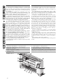 6
6
-
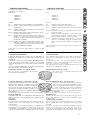 7
7
-
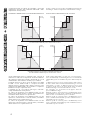 8
8
-
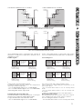 9
9
-
 10
10
-
 11
11
-
 12
12
-
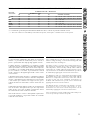 13
13
-
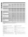 14
14
-
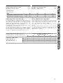 15
15
-
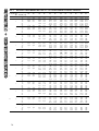 16
16
-
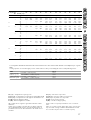 17
17
-
 18
18
-
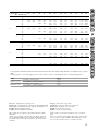 19
19
-
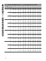 20
20
-
 21
21
-
 22
22
-
 23
23
-
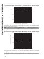 24
24
-
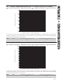 25
25
-
 26
26
-
 27
27
-
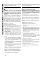 28
28
-
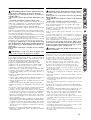 29
29
-
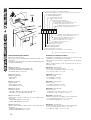 30
30
-
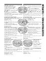 31
31
-
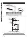 32
32
-
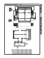 33
33
-
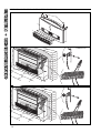 34
34
-
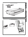 35
35
-
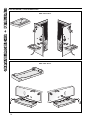 36
36
-
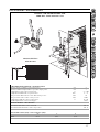 37
37
-
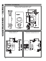 38
38
-
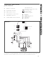 39
39
-
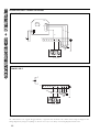 40
40
-
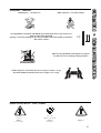 41
41
-
 42
42
-
 43
43
-
 44
44


Amermec Omnia HL PC Scheda dati
- Categoria
- Filtri dell'aria
- Tipo
- Scheda dati
in altre lingue
- English: Amermec Omnia HL PC Datasheet
Documenti correlati

Altri documenti
-
Aermec FCX Manuale del proprietario
-
Clint FVW 12÷74 universal fan coil ELMER Manuale utente
-
-
-
-
Whirlpool DBDO 93 LT X Guida d'installazione
-
MAXA VE Manuale del proprietario
-
Galletti FLAT S Installation, Use And Maintenance Manual
-
Samsung SGH-I900V Manuale utente
-
Whirlpool DS 2360 WH Guida d'installazione