Yamaha PM1D Manuale utente
- Categoria
- Adattatori per prese di corrente
- Tipo
- Manuale utente
Questo manuale è adatto anche per

PM1D System Software V1.4 Supplementary Manual
E

2
Contents
New functionality in system software V1.4 . . . . . . . . . . . . . . . . . . . . . . . . . . . . . . . . . . . . 3
Digital gain for input channels / insert inputs . . . . . . . . . . . . . . . . . . . . . . . . . . . . . . . . . . 3
Procedure . . . . . . . . . . . . . . . . . . . . . . . . . . . . . . . . . . . . . . . . . . . . . . . . . . . . . . . . . . 5
Digital gain added to 2TR IN . . . . . . . . . . . . . . . . . . . . . . . . . . . . . . . . . . . . . . . . . . . . . . . 6
BALANCE control for input channels / ST IN channels . . . . . . . . . . . . . . . . . . . . . . . . . . . 6
Procedure . . . . . . . . . . . . . . . . . . . . . . . . . . . . . . . . . . . . . . . . . . . . . . . . . . . . . . . . . . 8
Temporary monaural setting for paired input channels / ST IN channels . . . . . . . . . . . . 9
Front panel operating procedure. . . . . . . . . . . . . . . . . . . . . . . . . . . . . . . . . . . . . . . . 10
Screen operating procedure . . . . . . . . . . . . . . . . . . . . . . . . . . . . . . . . . . . . . . . . . . . 11
Operation when monaural is selected . . . . . . . . . . . . . . . . . . . . . . . . . . . . . . . . . . . . 11
M/S decoding. . . . . . . . . . . . . . . . . . . . . . . . . . . . . . . . . . . . . . . . . . . . . . . . . . . . . . . . . . 15
Procedure . . . . . . . . . . . . . . . . . . . . . . . . . . . . . . . . . . . . . . . . . . . . . . . . . . . . . . . . . 15
Tracking Recall function . . . . . . . . . . . . . . . . . . . . . . . . . . . . . . . . . . . . . . . . . . . . . . . . . . 17
Procedure . . . . . . . . . . . . . . . . . . . . . . . . . . . . . . . . . . . . . . . . . . . . . . . . . . . . . . . . . 18

New functionality in system software V1.4
3
Thank you for purchasing the CS1D. This booklet
explains the functionality that was added or changed in
version 1.4 of the PM1D software.
New functionality in system software V1.4
The following functionality and specifications have been
added in version 1.4 of the PM1D system software.
•
Digital gain has been added to input channels/
insert inputs
Digital gain has been added to input channels and
insert inputs, allowing you adjust the input sensitiv-
ity in the digital domain. Digital gain can be used in
input channels and insert inputs to which an AD
card, digital I/O card, 2TR IN, GEQ, or EFF are
assigned.
Digital gain has been added to the six 2TR IN inputs.
The sensitivity of the signal that is input to each 2TR
IN can be adjusted in the digital domain, indepen-
dently for L and R.
•
BALANCE has been added to PAN mode of the
input channels
The PAN parameter of an input channel can now be
switched to a BALANCE parameter.
For adjacent odd-numbered/even-numbered input
channels, you can switch the PAN parameter to a
BALANCE parameter.
•
New capability to temporarily set paired input
channels/ST IN channels to monaural
The signals from paired input channels or ST IN
channels can now be converted into monaural. As
the monaural conversion method, you can select L-
MONO (only the signal of the odd-numbered chan-
nel), R-MONO (only the signal of the even-num-
bered channel), or L,R-MONO (the signals of both
channels mixed).
•
M/S decoding functionality
“M/S decoding functionality” has been added, allow-
ing a two-channel signal input from a MS mic to be
converted into a L/R signal
•
Tr acking Recall function
The newly added “Tracking Recall” function lets you
add a previously-specified offset value to the value of
each fader when you recall a scene.
Changes
•
In the PAN/ROUTING function CH to MIX
screen, the send level knob to the MATRIX bus is
now displayed in gray to match the color of the
encoder on the CS1D. This makes it easier to dis-
tinguish the MIX send level knob from the send
level knob of the MATRIX/ST ROUTING func-
tion that sends the signal to the MATRIX bus.
•
The rotational angle of the encoder-type knobs in
the screen now matches the angle of the encoder
knobs of the CS1D front panel. The index mark-
ings have changed in conjunction with this.
•
Since V1.4 adds BALANCE to the PAN mode, the
line in the screen that indicates the encoder knob
position is now displayed in red for PAN (same as
before) and white for BALANCE, to make it eas-
ier to distinguish the setting. In the MATRIX/ST
function MATRIX/ST ROUTING screen as well,
the encoder knob positions are displayed in red
for PAN (same as before) and white for BAL-
ANCE.
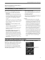
Digital gain for input channels/insert inputs
Digital gain has been added to input channels or insert
inputs that are assigned to AD cards, digital I/O cards,
2TR IN, GEQ, or EFF. By using this, the input sensitivity
can be adjusted in the digital domain even for input
sources that do not have an analog head amp.
Since digital gain has been added, the input channel/
insert input displays in the IN HA/INSERT, IN CH
VIEW, INPUT UNIT, and MONITOR A/MONITOR B
screens have changed as follows.
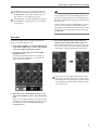
■
If an AD card (LMY4-AD) is assigned
Digital gain

PM1D Manager for Windows Operating manual
4
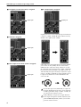
■
If a digital I/O card (MY card) is assigned
■
If 2TR IN is assigned
■
If the output of an effect return is assigned
■
If a GEQ output is assigned
Digital gain can be used to adjust the input sensitivity in
a range of +10 dB– –20 dB (the knob will not turn any
further to the right beyond –20 dB).
Only in the case of the digital gain for an input channel,
you can also use the [GAIN] encoder of the CS1D's
INPUT block to adjust the setting. In this case as well,
the adjustable range for the input is +10 dB– –20 dB (the
knob will not turn any further to the right beyond –20
dB). Internally, the input sensitivity is adjusted in a gain
range of –10 dB to +20 dB. If you want a digital source to
be input at nominal level, set the GAIN knob in the
screen to 0 dB.
If a mic/line input card (LMY2-ML) is assigned to
an input channel/insert input, the screen will show
an analog gain knob (range: +10 dB– –68 dB), just
as in the previous software version.
If TB (talkback) is assigned to an input channel/
insert input, the input level will be adjusted by the
panel TALKBACK [LEVEL] volume, just as in the
previous software version.
Digital gain
Digital gain
Digital gain
Digital gain
GAIN
-68+10
GAIN
-68+10

Digital gain for input channels/insert inputs
5
If 2TR IN is assigned to an input channel/insert
input, the gain settings of the 2TR IN screen and
the HA/INSERT screen will be linked. These set-
tings cannot be set to different positions.
The digital gain of an input channel/insert input to
which 2TR IN is assigned will not be saved in the
scene memory.
Hint
Settings for the digital gain of an input card are saved
in the unit library. Also, if the UNIT parameters of
the corresponding channel are set to Recall Safe, the
Recall Safe setting will also apply to the digital gain of
the input card.
Settings for the digital gain of EFF/GEQ are saved in
the scene memory. If the corresponding internal
effect/GEQ is set to Recall Safe, the Recall Safe setting
will also apply to the digital gain of the correspond-
ing EFF/GEQ.
Procedure
To adjust the digital gain of an input channel/insert
input, use the following procedure.
1. In the INPUT PATCH screen (IN PATCH function),
assign either an ML card or a source other than TB
to the desired input channel/insert input.
2. Access the corresponding screen of the IN HA/
INSERT function.
The following illustration shown an example of
when an AD card (LMY4-AD) is assigned to the
input channel/insert input.
3. Move the cursor to the GAIN knob in the screen,
and turn the [DATA] encoder to adjust the digital
gain.
In the case of an input channel, you can also use the
[GAIN] encoder in the INPUT block of the CS1D, or
the [GAIN] encoder in the SELECTED INPUT
CHANNEL block.
4. If you want to link the gain setting of adjacent
channels, click GAIN GANG switch to turn it on.
If the GAIN GANG button is on, adjacent odd-num-
bered/even-numbered channels will have their gain
setting linked (while maintaining the offset value).
You can also use the GAIN GANG button to link
analog gain and digital gain. However, when either
the analog gain or the digital gain reaches the limit
of its adjustment, neither channel will be adjustable
beyond this point.

PM1D Manager for Windows Operating manual
6
Digital gain added to 2TR IN
Digital gain has been added to the six 2TR IN inputs,
allowing you to adjust the input sensitivity in the digital
domain. The sensitivity of the signal that is input to each
2TR IN can be adjusted independently for L and R.
In conjunction with this, the display in the 2TR IN
screen (MON/CUE function) has changed as follows.
Hint
Digital gain is valid even if ANALOG is selected as
the source for 2TR IN 1 or 2TR IN 2. In this case, the
setting adjusts the sensitivity after AD conversion.
BALANCE control for input channels/ST IN channels
As necessary, you can now control the BALANCE
parameter instead of the PAN parameter for adjacent
odd-numbered/even-numbered input channels or ST IN
channels.
To do this, access the PAN/ROUTING function CH to
MIX screen, and turn on the PAN MODE section BAL-
ANCE button.
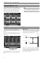
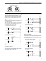
When the BALANCE button is on, the signal flow from
those two channels to the various buses will change as
follows.
■
STEREO bus
The PAN parameter that sends the signal to the STEREO
bus will change to a BALANCE parameter. (A BAL knob
will be displayed instead of a PAN knob in the PAN/
ROUTING function CH to MIX screen.)
In this case, the signal of the odd-numbered input chan-
nel will be sent only to the L channel, and the signal of
the even-numbered input channel will be sent only to
the R channel. The BAL knob will adjust the volume of
the two channels in tandem.
BALANCE button
ON
ON
STEREO L
STEREO R
BALANCE
INPUT CHANNEL 1
INPUT CHANNEL 2

BALANCE control for input channels/ST IN channels
7
■
VARI type MIX bus
If a VARI type MIX bus is paired, the PAN parameter of
the MIX bus will change to a BALANCE parameter. (A
BAL knob will be displayed instead of a PAN knob in the
PAN/ROUTING function CH to MIX screen.)
In this case, the signal of the odd-numbered input chan-
nel will be sent only to the odd-numbered MIX bus, and
the signal of the even-numbered input channel will be
sent only to the even-numbered MIX bus. The BAL
knob will adjust the volume of the two signals in tan-
dem.
In addition, if the VARI PAN LINK button is on for
either of these two channels, the MIX bus BAL knob will
be linked with the STEREO bus BAL knob. If you oper-
ate either BAL knob of the STEREO bus or MIX bus, the
remaining three BAL knobs will operate in tandem.
Hint
Even if the BALANCE button is on, the signal that is
sent from those input channels to a VARI type MIX
bus will not be affected unless the MIX bus is paired.
■
FIX type MIX bus
If the FIXED MIX PAN button is on for either of the two
channels whose PAN MODE is set to BALANCE, the sig-
nal that flows from the corresponding input channel
through the BALANCE parameter will be sent to the FIX
type MIX bus. At this time, the signal of the odd-num-
bered input channel will be sent only to the odd-num-
bered MIX bus, and the signal of the even-numbered
input channel will be sent only to the even-numbered
MIX bus.
BAL knob
MIX 1 (VARI)
MIX 2 (VARI)
BALANCE
BALANCE
ON
ON
INPUT CHANNEL 1
INPUT CHANNEL 2
STEREO L
STEREO R
ON
ON
INPUT CHANNEL 1
INPUT CHANNEL 2
BALANCE
STEREO L
STEREO R
MIX 1
MIX 2

PM1D Manager for Windows Operating manual
8
Hint
Even if the BALANCE button is on, the signal that is
sent from those input channels to a FIX type MIX
bus will not be affected if the FIXED MIX PAN but-
ton is turned off for both channels.
In addition, the operation will change as follows if the
PAN MODE “BALANCE” button is on.
•
Of the two channels for which the BALANCE button
is turned on, if you save one of the channels in the
channel library, the PAN MODE setting will be saved
for the other channel even if it is not paired.
•
When you recall data from the channel library, the
PAN MODE or PAN value will not be recalled if the
PAN MODE setting differs between the recall source
and recall destination. However only if the recall des-
tination is paired, the PAN MODE and PAN value
will be recalled.
•
When you copy channel data, the PAN MODE and
PAN value will not be copied if the PAN MODE set-
ting differs between the copy source and copy desti-
nation. However, the PAN MODE and PAN value
will be copied only if the copy destination is paired.
•
When recalling a channel library or copying a chan-
nel, if the channel that is not being recalled or copied
is set to a PAN mode of BALANCE or if VARI PAN
LINK is turned on, the MIX “BALANCE” value will
be the same as the TO ST “BALANCE” in order to
avoid inconsistencies between the TO ST value and
MIX BALANCE value of the recalled or copied chan-
nels.
•
When recalling scene data from a scene memory, and
the PAN MODE setting of odd-numbered/even-
numbered input channels does not match because
one of the channels is set to Recall Safe, the PAN
MODE or PAN values will not be recalled.
•
For an input channel whose MIX send is set to Recall
Safe, the PAN/BALANCE of the MIX send will also
be subject to Recall Safe. For this reason if the PAN
MODE settings of the recall source and recall desti-
nation do not match, it will not be possible to recall
the PAN MODE or PAN/BALANCE values.
•
In the case of an input channel in which the PAN
MODE is BALANCE and the MIX send is set to
Recall Safe, recalling a scene in which “PAN
MODE=BALANCE, VARI PAN LINK=on” will cause
the BALANCE value of the STEREO send to be
recalled, but the BALANCE of the MIX send will be
subject to Recall Safe. In this state, it is possible that
BALANCE values of the STEREO send and MIX
send will be inconsistent, so VARI PAN LINK will
therefore be forcibly switched off. The PAN parame-
ter fade function (INPUT CH PANNING, located in
the SCENE function FADE TIME screen) can also be
used when the BALANCE button is on. However,
you must enable INPUT CH PANNING for both the
odd-numbered and even-numbered channels.
•
If the PAN MODE is switched from PAN to BAL-
ANCE (or vice versa) while the PAN parameter fade
function is being executed, the PAN parameter fade
function will be aborted for that channel.
Procedure
Here's the procedure for operating the BALANCE
parameter of input channels/ST IN channels.
1. Access the PAN/ROUTING function CH to MIX
screen.
2. In the VARI & FIX area, turn on the TO ST button
for adjacent odd-numbered/even-numbered chan-
nels or for a ST IN channel.
3. In the PAN MODE area, turn on the BALANCE but-
ton of the corresponding channels.
The PAN knobs in the screen (position indicator dis-
played in red) will change to BAL knobs (position
indicator displayed in white), and will function as
the balance parameter.
Hint
The BALANCE parameter is valid even if you do not
enable pairing between the input channels.
4. Move the cursor to one of the BAL knobs, and turn
the [DATA] encoder to adjust the value of the BAL-
ANCE parameter.
The BAL knobs of both channels will move in tan-
dem.
The BALANCE parameter can also be controlled
from the INPUT block [PAN] encoder on the CS1D's
front panel, or from the SELECTED INPUT CHAN-
NEL block [PAN] encoder. In this case, the LEDs sur-
rounding the [PAN] encoder will display as follows.

Temporary monaural setting for paired input channels/ST IN channels
9
Temporary monaural setting for paired input channels/ST IN channels
The input signal from paired input channels or ST IN
channels can now be temporarily converted to monau-
ral. You can select one of the following three modes.
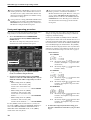
■
Set to L-MONO
The channels will remain paired, but the signal will tem-
porarily become a monaural signal containing only the
odd-numbered channel.
The [ON] switch of the even-numbered channel will be
forced off, and the PAN (BALANCE) of the odd-num-
bered channel will be set to the center.
■
Set to R-MONO
The channels will remain paired, but the signal will tem-
porarily become a monaural signal containing only the
even-numbered channel.
The [ON] switch of the odd-numbered channel will be
forced off, and the PAN (BALANCE) of the even-num-
bered channel will be set to the center.
■
Set to LR-MONO
The channels will remain paired, but the signal will tempo-
rarily become a monaural signal containing both channels.
The PAN (BALANCE) of both channels will be set to the
center.
PAN
R
PAN
L
Odd-numbered (L) channel Even-numbered (R) channel
Value of the BALANCE parameter
Always litAlways lit
ON
Fixed at OFF
STEREO L
STEREO R
INPUT CHANNEL 1
INPUT CHANNEL 2
PAN=CENTER
When PAN MODE is other than BALANCE
ON
STEREO L
STEREO R
INPUT CHANNEL 1
INPUT CHANNEL 2
BALANCE=CENTER
When PAN MODE is BALANCE
Fixed at OFF
ON
STEREO L
STEREO R
INPUT CHANNEL 1
INPUT CHANNEL 2
PAN=CENTER
Fixed at OFF
When PAN MODE is other than BALANCE
ON
STEREO L
STEREO R
INPUT CHANNEL 1
INPUT CHANNEL 2
BALANCE=CENTER
When PAN MODE is BALANCE
Fixed at OFF
ON
ON
STEREO L
STEREO R
INPUT CHANNEL 1
INPUT CHANNEL 2
PAN=CENTER
PAN=CENTER
When PAN MODE is other than BALANCE
ON
ON
STEREO L
STEREO R
INPUT CHANNEL 1
INPUT CHANNEL 2
BALANCE=CENTER
BALANCE=CENTER
When PAN MODE is BALANCE

PM1D Manager for Windows Operating manual
10
Even if L-MONO or R-MONO is selected, you can
edit the parameters of the channel that was forced
off. (However, the [ON] switch will be fixed at Off
until you defeat the L-MONO or R-MONO setting,
and cannot be changed.)
A new preference setting [L,R-MONO SELECT ON
PANEL] has been added to the UTILITY function
PREFERENCE screen, allowing you to switch to the
LR-MONO setting from the front panel.
In previous versions of the system software, it was
always possible to switch between PAIR and
MONO from the front panel. However, a new pref-
erence setting [PROHIBIT PAIR CHANGE ON
PANEL] has been added to the UTILITY function
PREFERENCE screen, allowing you to enable/dis-
able this function from being operated from the
front panel.
Front panel operating procedure
Here's how paired input channels/ST IN channels can be
temporarily set to monaural from the front panel.
1. Access the UTILITY function PREFERENCE
screen, and turn on the L,R-MONO SELECT ON
PANEL button.
This allows the temporary change from stereo to
monaural to be made from the front panel.
2. Specify pairing for any two adjacent odd-num-
bered/even-numbered input channels.
3. Use the front panel [SEL] switches and [SHIFT]
switches to select one of the following three ways in
which the channels will be temporarily set to mon-
aural.
•While holding down the [SHIFT]
switch Press and hold the [SEL]
switch of the odd-numbered (L)
channel
......................................... select L-MONO
•While holding down the [SHIFT]
switch Press and hold the [SEL]
switch of the even-numbered (R)
channel
........................................ select R-MONO
•While holding down the [SHIFT]
switch Press and hold the [SEL]
switches of both channels
............select LR-MONO
For the [SHIFT] switch described above, you may use
any of the [SHIFT] switches in CHANNEL SELECT sec-
tion of the SELECTED INPUT CHANNEL block or
SELECTED OUT CHANNEL block, or the [SHIFT]
switch of the data entry block.
You can use the same procedure as described above to
change one temporary monaural setting to a different
temporary monaural setting.
On the panel, the INPUT [NAME] indicator will blink
alternately between the name of the channel that was set to
temporary monaural and the name of the monaural mode.
For a channel that is turned off, the INPUT [NAME] indi-
cator will dimly display the channel name. The [NAME]
indicator will also be displayed in the same way when these
channels are recalled to a DCA fader. For details on opera-
tion when a monaural setting is selected, refer to page 11.
• Name indicator
For L-MONO:
L ch: Alternately display
and the chan
-
nel name (the brightness depends on the
on/off status)
R ch: Alternately display and the chan
-
nel name (dimly)
For R-MONO:
L ch: Alternately display and the chan
-
nel name (dimly)
R ch: Alternately display and the chan
-
nel name (the brightness depends on the
on/off status)
For LR-MONO:
L ch: Alternately display
and the chan
-
nel name (the brightness depends on the
on/off status)
R ch: Alternately display
and the chan
-
nel name (the brightness depends on the
on/off status)
4. To defeat the temporary monaural setting, press
the same combination of switches as you pressed in
step 3.
L ch
R ch
L ch
R ch
L ch
R ch

Temporary monaural setting for paired input channels/ST IN channels
11
The temporary monaural mode will be defeated, and the
PAN (BALANCE) will return to the positions specified
for the pair.
The MIX send PAN setting (or BALANCE setting)
will be set to the same position as TO ST.
Hint
In order to prevent accidents, it is possible to pro-
hibit the operator from using the [SEL] switches to
set/cancel pairing. To prohibit this, go to the PREF-
ERENCE screen and turn the PROHIBIT PAIR
CHANGE ON PANEL button on.
Screen operating procedure
Here's how paired input channels/ST IN channels can be
temporarily set to monaural from within the screen.
1. Specify pairing for the desired adjacent odd-num-
bered/even-numbered input channels.
2. Access a screen (such as the IN HA/INSERT func-
tion) that shows the heart symbols, and for the
channels that you want to temporarily set to mon-
aural, click the pair/stereo indicator heart symbol
while you hold down the [SHIFT] switch of the data
entry block. Alternatively, move the cursor to the
heart symbol, then hold down the [SHIFT] switch
and press the [ENTER] switch.
The following popup window will appear.
Only the [SHIFT] switch of the data entry block
can be used to select the temporary monaural set-
ting from the screen.
Hint
If you click without holding down the [SHIFT]
switch, you will switch between conventional pair-
ing/monaural.
3. Move the cursor to the desired button, and press
the [ENTER] key. The setting will be made the
instant you press the [ENTER] key.
Each button has the following meaning.
...............................Specify L-MONO
...............................Specify R-MONO
...............................Specify LR-MONO
If none of the above three buttons are on, the channels
will be paired.
When you make the monaural setting, the heart symbol
will change as follows.
Hint
The same type of popup window will appear if you
hold down the [SHIFT] switch and press the
[ENTER] switch on the heart symbol of an unpaired
channel. However, it will not be possible to select L-
MONO/R-MONO/LR-MONO.
4. To cancel the temporary monaural setting, hold
down the [SHIFT] switch and click the above heart
symbol once again, press the same button as you
selected in step 3, and press OK.
The monaural setting will be cancelled, and the PAN
(BALANCE) will return to its position at the time it
was paired.
Hint
By moving the cursor to a different button and press-
ing the [ENTER] switch, you can move to a different
channel for which to make temporary monaural set-
tings.
Also, pairing can be defeated in the usual way even if
channels are temporarily set to monaural.
Operation when monaural is selected
The following points describe details of operation when
the L-MONO, R-MONO, or LR-MONO settings are
selected.
• Input channels that are temporarily set to monaural
can be changed to L-MONO, R-MONO, LR-MONO,
pairing defeated, or paired settings. However, the
input signal of a ST IN channel cannot be set to
monaural (pairing defeated).
• When you return to a paired state after selecting tem-
porary monaural, the PAN setting and PAN mode
will return to the PAN/BALANCE position that had
been in effect when pairing was specified.
• When the signal of an input channel is sent to a MIX
bus, any temporary monaural mode L-MONO, R-
MONO, or LR-MONO will operate in the same way
as normal monaural (pairing defeated) mode.
L-MONO LR-MONOR-MONO
Conventional
PAIR

PM1D Manager for Windows Operating manual
12
However, CUE on/off and Recall Safe that are not set
independently for L and R in a ST IN channel will be
linked or non-linked as a pair, even if LR-MONO is
selected.
For a ST IN channel, these parameters will always be
linked regardless of the temporary monaural setting.
• If the STEREO bus send PAN mode is set to BAL-
ANCE for an input channel, the MIX bus is paired,
and the MIX bus type is VARI, the MIX bus PAN
mode will also be BALANCE.
(The BALANCE value can be set individually.)
However if the channel is changed from a temporary
monaural setting to Pair, the MIX bus PAN position
will return to the same position as the STEREO bus
PAN/BALANCE that was in effect when the channel
was paired.
•
In the front panel SELECTED INPUT CHANNEL
block, the CHANNEL SELECT indicators MONO and
PAIR will both light if any of the temporary monaural
modes L-MONO/R-MONO/LR-MONO are selected.
Other displays are the same as in software version 1.3.
• Copying between paired channels that are tempo-
rarily set to monaural can be performed between
paired channels. Copying to channels that are tem-
porarily set to monaural can be performed only from
a L-MONO/R-MONO/LR-MONO/PAIR channel. It
is not possible to copy from a temporarily monaural
channel to a monaural channel.
• For a temporarily monaural channel, the display in
the CH VIEW screen that is accessed by the front
panel LCD FUNCTION ACCESS [CH VIEW] switch
will be the same as the MONO display.
• Channel libraries can be stored or recalled in monau-
ral if paired channels are set to any temporary mon-
aural setting L-MONO, R-MONO, or LR-MONO.
Libraries cannot be recalled or stored as a pair.
•
CUE will function according to the pairing on/off set-
ting, and will not be affected by this temporary mon-
aural setting. Just as in software version 1.3, CUE will
operate in the same way as CUE for paired channels,
regardless of this temporary monaural setting. CUE
on/off is linked for L/R channels, and in the case of
PFL, the L channel signal will be sent to the L side of
the CUE bus, and the R channel signal to the R side of
the CUE bus (i.e., CUE in stereo). In the case of AFL,
operation will be the same as CUE for paired channels.
If the L-MONO or R-MONO temporary monaural
setting is selected, turning off either channel will cause
that channel to no longer be sent to the CUE bus.
• Recall Safe will operate according to the pair on/off
setting, regardless of the temporary monaural set-
ting. If Recall Safe is specified for only one of the two
channels, and you recall a scene for channels that are
set to monaural, a warning message will be displayed
to inform you that monaural will be cancelled even if
the channel contains Recall Safe parameters. Then
pairing will be cancelled. Only the channel that is not
set to Recall Safe will be recalled. In the case of L-
MONO, recalling the R channel will cause that chan-
nel to be recalled in an Off state. In the case of L-
MONO, recalling the L channel will cause that chan-
nel to be recalled in an Off state.
• If you recall channel library no.00, these temporary
monaural settings will be the same as for unpaired
channels. In other words, the PAN mode will remain
as it was, and the PAN/BALANCE will be set to the
center. For paired channels, the PAN mode will be
forced to INDIVIDUAL, and operation will be the
same as in software version 1.30.
• The fade time will operate according to the pair on/
off setting, without being affected by this temporary
monaural setting. When paired, the fade time of the
two channels will be linked.
• Insert on/off, insert point, and direct point can now
be set separately for L/R even if one of the temporary
monaural modes L-MONO/R-MONO/LR-MONO
are selected. (This setting is stored in the scene mem-
ory.)
• If a channel library is recalled to the channel that is
forced off by a L-MONO or R-MONO setting (i.e.,
the R channel in the case of L-MONO, or the L chan-
nel in the case of R-MONO), the recalled channel
will be forced off.
• The KEY IN link for GATE or COMP will not be
changed by any of these temporary monaural set-
tings. LINK will be turned on only if monaural is
changed to pair. LINK will not be turned off when
the setting is changed from pair to link.

Temporary monaural setting for paired input channels/ST IN channels
13
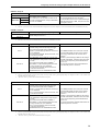
If PAN is changed:
*1: PAN refers to any of the pan modes INDIVIDUAL PAN, GANG PAN, or INVERTED GANG PAN.
*2: This is the operation that occurs when the PAN MODE is changed in the screen. If it is changed by a scene recall, it will follow the stored PAN/BALANCE setting.
If PAIR is changed:
*1: PAN refers to any of the pan modes INDIVIDUAL PAN, GANG PAN, or INVERTED GANG PAN.
*1: PAN refers to any of the pan modes INDIVIDUAL PAN, GANG PAN, or INVERTED GANG PAN.
*2: This is the operation that will occur when pairing settings are changed in the screen or panel. If pairing settings were changed as a result of a scene recall, the stored
PAN/BALANCE status will be followed.
*3: “Parameters” refers to parameters that are linked when channels are paired.
PAN*
1
→ BALANCE BALANCE → PAN .*
1
MONO mode
• BALANCE will be CENTER.*
2
• The PAN that is sent to a MIX bus that is both
paired and VARI-type will change to BALANCE,
and set to CENTER.
• The L channel PAN will be set to far left, and the
R channel PAN will be set to far right.*
2
• The BALANCE that is sent to a paired VARI-type
MIX bus will change to PAN, and panned to left
and right as above.
PAIR mode
PAIR
L-MONO
R-MONO
Cancel pairing → Specify pairing
Paired
Pairing defeated
•PAN setting remains as is.
Paired
→
L-MONO
L-MONO
→
Paired
• The PAN value of the L/R channels and the PAN
MODE setting will be temporarily preserved.
• The L/R channel PAN will be CENTER.*
2
•PAN to a paired VARI-type MIX bus will also be
set to CENTER.
• The R channel ON/OFF will be turned OFF, and
cannot be turned ON.
• The PAN/BALANCE value of the L/R channels
and the PAN MODE will return to the settings
that were in effect when the channels were
paired.*
2
•PAN to a paired VARI-type MIX bus will change
to PAN or BALANCE, and will be set to the same
value as the temporarily preserved PAN value
for TO ST.
• R-channel parameters other than PAN will be
set identically to the L channel.*
3
• The BALANCE value of the L/R channels and
the PAN MODE setting will be temporarily pre-
served.
• The L/R channel PAN will be CENTER.*
2
• BALANCE to a paired VARI-type MIX bus will
change to PAN, and set to CENTER.
• The R channel ON/OFF will be turned OFF.
(Cannot be turned ON.)
•PAN MODE will be set to INDIVIDUAL PAN.
Paired
→
R-MONO R-MONO
→
Paired
• The PAN value of the L/R channels and the PAN
MODE setting will be temporarily preserved.
• The L/R channel PAN will be CENTER.*
2
•PAN to a paired VARI-type MIX bus will also be
set to CENTER.
• The L channel ON/OFF will be turned OFF, and
cannot be turned ON.
• The PAN/BALANCE value of the L/R channels
and the PAN MODE will return to the settings
that were in effect when the channels were
paired.*
2
•PAN to a paired VARI-type MIX bus will change
to PAN or BALANCE, and will be set to the same
value as the temporarily preserved PAN value
for TO ST.
• L-channel parameters other than PAN will be set
identically to the R channel.*
3
• The BALANCE value of the L/R channels and
the PAN MODE setting will be temporarily pre-
served.
• The L/R channel PAN will be CENTER.*
2
• BALANCE to a paired VARI-type MIX bus will
change to PAN, and set to CENTER.
• The L channel ON/OFF will be turned OFF.
(Cannot be turned ON.)
•PAN MODE will be set to INDIVIDUAL PAN.

PM1D Manager for Windows Operating manual
14
*1: PAN refers to any of the pan modes INDIVIDUAL PAN, GANG PAN, or INVERTED GANG PAN.
*2: This is the operation that will occur when pairing settings are changed in the screen or panel. If pairing settings were changed as a result of a scene recall, the stored
PAN/BALANCE status will be followed.
*3: “Parameters” refers to parameters that are linked when channels are paired.
*1: PAN refers to any of the pan modes INDIVIDUAL PAN, GANG PAN, or INVERTED GANG PAN.
*1: PAN refers to any of the pan modes INDIVIDUAL PAN, GANG PAN, or INVERTED GANG PAN.
*1: PAN refers to any of the pan modes INDIVIDUAL PAN, GANG PAN, or INVERTED GANG PAN.
Paired
→
LR-MONO LR-MONO
→
Paired
• The PAN value of the L/R channels and the PAN
MODE setting will be temporarily preserved.
• The L/R channel PAN will be CENTER.*
2
•PAN to a paired VARI-type MIX bus will also be
set to CENTER.
• The PAN/BALANCE value of the L/R channels
and the PAN MODE will return to the settings
that were in effect when the channels were
paired.*
2
•PAN to a paired VARI-type MIX bus will change
to PAN or BALANCE, and will be set to the same
value as the temporarily preserved PAN value
for TO ST.
• R-channel parameters other than PAN will be
set identically to the L channel.*
3
• The BALANCE value of the L/R channels and
the PAN MODE setting will be temporarily pre-
served.
• The L/R channel PAN will be CENTER.*
2
• BALANCE to a paired VARI-type MIX bus will
change to PAN, and set to CENTER.
•PAN MODE will be set to INDIVIDUAL PAN.
L-MONO
→
Pairing defeated
R-MONO
→
Pairing defeated
LR-MONO
→
Pairing defeated
Pairing defeated
→
L-MONO
Pairing defeated
→
R-MONO
Pairing defeated
→
LR-MONO
• The L/R channel PAN setting and PAN MODE
will not change.
•PAN to a paired VARI-type MIX bus will not
change.
• These operations are invalid.
• The BALANCE setting of the L/R channels and
the PAN MODE setting will not change.
• The PAN setting to a paired VARI-type MIX bus
will not change.
L-MONO
→
R-MONO R-MONO
→
L-MONO
• The PAN value of the L/R channels and the PAN
MODE setting will not change.
•PAN to a paired VARI-type MIX bus will also
remain unchanged.
• The R channel ON/OFF will be set to the same
setting as the L channel, and the L channel ON/
OFF setting will be turned OFF.
• The PAN value of the L/R channels and the PAN
MODE setting will not change.
•PAN to a paired VARI-type MIX bus will also
remain unchanged.
• The L channel ON/OFF will be set to the same
setting as the R channel, and the R channel ON/
OFF setting will be turned OFF.
• The BALANCE value of the L/R channels and
the PAN MODE setting will not change.
• BALANCE to a paired VARI-type MIX bus will
also remain unchanged.
• The R channel ON/OFF will be set to the same
setting as the L channel, and the L channel ON/
OFF setting will be turned OFF.
• The BALANCE value of the L/R channels and
the PAN MODE setting will not change.
• BALANCE to a paired VARI-type MIX bus will
also remain unchanged.
• The L channel ON/OFF will be set to the same
setting as the R channel, and the R channel ON/
OFF setting will be turned OFF.
L-MONO
→
LR-MONO R-MONO
→
LR-MONO
• The PAN value of the L/R channels and the PAN
MODE setting will not change.
•PAN to a paired VARI-type MIX bus will also
remain unchanged.
• The R channel ON/OFF will be set to the same
setting as the L channel, and the L channel ON/
OFF setting will not change.
• The PAN value of the L/R channels and the PAN
MODE setting will not change.
•PAN to a paired VARI-type MIX bus will also
remain unchanged.
• The L channel ON/OFF will be set to the same
setting as the R channel, and the R channel ON/
OFF setting will not change.
• The PAN (BALANCE) value of the L/R channels
and the PAN MODE setting will not change.
•PAN to a paired VARI-type MIX bus will also
remain unchanged.
• The R channel ON/OFF will be set to the same
setting as the L channel, and the L channel ON/
OFF setting will not change.
• The PAN (BALANCE) value of the L/R channels
and the PAN MODE setting will not change.
•PAN to a paired VARI-type MIX bus will also
remain unchanged.
• The L channel ON/OFF will be set to the same
setting as the R channel, and the R channel ON/
OFF setting will not change.

M/S decoding
15
*1: PAN refers to any of the pan modes INDIVIDUAL PAN, GANG PAN, or INVERTED GANG PAN.
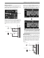
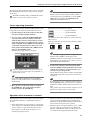
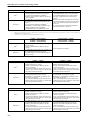
M/S decoding
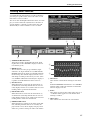
M/S decoding functionality is now provided, allowing a two-channel signal input from a MS mic through adjacent odd-
numbered/even-numbered input channels to be converted into L/R signals.
1
M/S DECODE ON/OFF button
This switches the M/S decoding function on/off, in
groups of two adjacent odd-numbered/even-num-
bered channels (or a stereo input channel). The M/S
decode function can be turned on even for channels
that are not specified as a stereo pair.
2
S-GAIN knob
This sets the level difference of the S mic, relative to
the level of the M mic. The current value is shown in
the numerical box at the right.
At the MONO position, the S mic level will be -infin-
ity. At the EXP.ST position, the S mic level will be
+10 dB.
At the STEREO position, the levels of the M mic and
S mic will be the same.
3
Unit type/ID number/channel number
These indicate the type of input assigned to the cor-
responding channel, the ID number, and the channel
number of the input jack.
4
Channel/Pair settings
These indicate the number of the currently displayed
input channel and the pairing status. You can also
click the heart symbol in this screen to set or defeat
pairing.
Procedure
Here's how to decode an MS mic input signal.
1. Connect the MS mics to two channels of an input
unit, and assign them to two adjacent odd-num-
bered/even-numbered channels.
Assign the M mic to the odd-numbered (L) channel,
and the S mic to the even-numbered (R) channel.
2. If necessary, specify the above two channels as a
pair.
MS decoding can be used even if the input channels
are not paired.
LR-MONO
→
L-MONO LR-MONO
→
R-MONO
• The PAN value of the L/R channels and the PAN
MODE setting will not change.
•PAN to a paired VARI-type MIX bus will also
remain unchanged.
• The R channel ON/OFF will be turned OFF, and
the L channel ON/OFF setting will not change.
• The PAN value of the L/R channels and the PAN
MODE setting will not change.
•PAN to a paired VARI-type MIX bus will also
remain unchanged.
• The L channel ON/OFF will be turned OFF, and
the R channel ON/OFF setting will not change.
• The PAN (BALANCE) value of the L/R channels
and the PAN MODE setting will not change.
•PAN to a paired VARI-type MIX bus will also
remain unchanged.
• The R channel ON/OFF will be turned OFF, and
the L channel ON/OFF setting will not change.
• The PAN (BALANCE) value of the L/R channels
and the PAN MODE setting will not change.
• BALANCE to a paired VARI-type MIX bus will
also remain unchanged.
• The L channel ON/OFF will be turned OFF, and
the R channel ON/OFF setting will not change.
1
2
3
4

PM1D Manager for Windows Operating manual
16
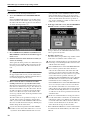
3. Access the PAN/ROUTING function M/S screen.
4. Click the M/S DECODE ON/OFF button for the
corresponding two channels, to turn the button on.
With this setting, the odd-numbered (L) channel will
input the (M+S) signal, and the even-numbered (R)
channel will input the (M–S) signal (the M signal
summed with the inverted-phase S signal).
Even if only one signal (the M signal or S signal)
is patched to an input channel, turning M/S
DECODE on will send the signal to both chan-
nels.
5. Move the cursor to the S-GAIN knob, and turn the
[DATA] encoder to adjust the level of the S mic rela-
tive to the M mic.
At the MONO position, S = –infinity. At the STE-
REO position, M = S. At the EXP.ST position, S =
+10 dB.
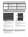
M/S decoding is performed immediately after DE-
EMPHASIS and immediately before ATT. (attenua-
tor).
For this reason, please note that when M/S decod-
ing is on, the following meters will show the signal
level before M/S decoding.
•
The input unit meter displayed in the HA/INSERT
function screen
•
The screen/panel meters when the METER function
METERING POINT setting is set to PRE ATT.
•
The input unit meter displayed in the INPUT UNIT
screen (SYS/W.CLOCK function)
A headroom margin of approximately 18 dB is
maintained before M/S decoding. If the signal clips
while you are using M/S decoding, you can use the
attenuator to lower the level and input an
unclipped signal if the clipping is below the head-
room margin.
Since M/S decoding is a special function, it cannot
be copied between channels or saved in a channel
library. Also, the RESET BOTH button in the
CHANNEL PAIRING popup window will not be
valid.
UNIT
PATCH
PEAK
METER
(PRE ATT.)
DE-
EMPHASIS
M/S DECODE ATT.

Tracking Recall function
17
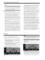
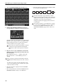
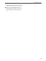
Tracking Recall function
A “Tracking Recall” function has been added, which lets
you add a pre-specified offset value to the value of each
fader when a scene is recalled.
You can use this Tracking Recall function when (for exam-
ple) you want to make fine adjustments to the faders of
specific channels, so that the specified offset value will
automatically be added each time a scene is recalled.
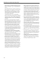
1
TRACKING RECALL button
This button switches Tracking Recall on/off. Track-
ing Recall is on when ENABLE is displayed (the but-
ton will turn green).
2
MODE buttons
These buttons select the group of channels (input
channels 1–48, input channels 49–96, MIX channels,
MATRIX channels) for which you will make Tracking
Recall settings. The channels displayed in the screen
will change according to the button you select. (How-
ever, STEREO A/B and DCA will always be displayed
regardless of the MODE button that is selected.)
3
SET ALL button
When this button is turned on, the ON buttons (6)
of all channels (including channels that are not cur-
rently displayed in the screen) will be turned on, and
tracking will be specified for all channels.
4
CLEAR ALL button
When this button is turned on, the ON buttons (6)
of all channels (including channels that are not cur-
rently displayed in the screen) will be turned off, and
tracking will be defeated for all channels.
5
OFFSET LOCK button
When this button is turned on, the sliders of all chan-
nels (including channels that are not currently dis-
played in the screen) will be displayed in gray, and it
will not be possible to change the offset value further.
6
ON buttons
These buttons enable/defeat tracking for each chan-
nel.
If the TRACKING RECALL button is set to ENABLE,
tracking will be enabled for channels for which this
button is displayed as ON.
7
Faders
These faders specify an offset value in the range of +/
–15 dB that will be applied to each channel when
tracking is enabled.
8
Offset values
These indicate the offset value for each channel.
1 2 5
34
6
7
8

PM1D Manager for Windows Operating manual
18
Procedure
Here's how to use the Tracking Recall function.
1. Access the SCENE function TRACKING RECALL
screen.
In the TRACKING RECALL screen, tracking can be
turned on/off for each channel, and you can specify
the offset value that will be applied to each channel
for which Tracking Recall is on.
2. Press a MODE button (INPUT 1-48, INPUT 49-96,
MIX, MATRIX) so that the desired channels appear
in the screen.
3. Click the ON button of the channels for which you
want to use tracking.
At this point, the fader position of a channel that you
have turned on by clicking will be memorized as the
reference position. Thus, the offset value will be set
to 0.
Hint
By clicking the SET ALL or CLEAR ALL buttons in
the upper right of the screen, you can enable/defeat
tracking for all channels (including channels that are
not currently displayed in the screen).
4. Raise or lower the faders of channels for which
tracking is turned on, to specify their offset value.
Move the front panel faders from the reference posi-
tions that were memorized in step 3. The distance of
this movement will be set as the offset value. The off-
set value can also be specified by moving the sliders
in the screen. However if you use the sliders in the
screen to specify the offset, the front panel faders will
not change position.
The offset value can be specified in a range of –15–0–
+15 dB. After you have specified the desired offset
values, you can turn on the OFFSET LOCK button in
the screen to make the sliders turn gray, disabling any
further change in the offset values.
If you move the front panel faders while OFFSET
LOCK is on, the offset value will not be re-set even
if you then defeat OFFSET LOCK. This is because
you may wish to defeat OFFSET LOCK in order to
make manual changes in the screen. If you move
the faders after defeating OFFSET LOCK, the offset
will be calculated from the reference position of
step 3 before tracking is recalled (an offset value of
0 dB), and set accordingly.
5. In the upper left of the screen, click the TRACKING
RECALL button to switch it to ENABLE.
In this example, the Tracking function was enabled
in step 5. However, the TRACKING RECALL button
can be operated at any time.
6. Recall the desired scene.
The offset values you specified in step 4 will be added
to the value of each fader in the recalled scene.
The faders of channels that are set to Recall Safe will
not change even if Tracking Recall is turned on. Nor
will the offset value change.
If the ENABLE button of the TRACKING RECALL
area is off, the specified offset value will not be
added to the recalled faders. The offset value will
return to zero when recall occurs unless the OFF-
SET LOCK button is on. If you want to set a specific
scene to the reference position (offset 0), you
should turn off the ENABLE button of the TRACK-
ING RECALL area and also turn off the OFFSET
LOCK button before recalling the scene.
If the ENABLE button of the TRACKING RECALL
area is on, and you recall a scene not set to Recall
Safe, the fader values that were stored in the scene
will be offset by the specified value for each channel
for which the Tracking function is on, and the fad-
ers will move to the closest possible location for the
calculated value.
In the case of channels that are newly paired due to
a recall, offset will be considered to be off unless the
ON buttons of those two channels are both turned
on, and the offset value will not be added. If the ON
buttons of both channels are on, then the offset
value will be the average of the two values.
•
If the OFFSET LOCK button is off for a channel that
is recalled from the channel library, the offset value
will be 0.

Tracking Recall function
19
•
If the OFFSET LOCK button is off for a channel that
is channel-copied, the offset value will also be copied.
When the power of the CS1D is turned off, and
then on once again, the ENABLE button of the
TRACKING RECALL area will be turned off for the
sake of safety, disabling the Tracking Recall func-
tion.

YAMAHA CORPORATION
IP 20 Pro Audio & Digital Musical Instrument Division
P.O. Box 3, Hamamatsu, 430-8651, Japan
Printed in Japan
-
 1
1
-
 2
2
-
 3
3
-
 4
4
-
 5
5
-
 6
6
-
 7
7
-
 8
8
-
 9
9
-
 10
10
-
 11
11
-
 12
12
-
 13
13
-
 14
14
-
 15
15
-
 16
16
-
 17
17
-
 18
18
-
 19
19
-
 20
20


Yamaha PM1D Manuale utente
- Categoria
- Adattatori per prese di corrente
- Tipo
- Manuale utente
- Questo manuale è adatto anche per
in altre lingue
- English: Yamaha PM1D User manual
- français: Yamaha PM1D Manuel utilisateur
- español: Yamaha PM1D Manual de usuario
- Deutsch: Yamaha PM1D Benutzerhandbuch
- русский: Yamaha PM1D Руководство пользователя
- Nederlands: Yamaha PM1D Handleiding
- português: Yamaha PM1D Manual do usuário
- dansk: Yamaha PM1D Brugermanual
- čeština: Yamaha PM1D Uživatelský manuál
- polski: Yamaha PM1D Instrukcja obsługi
- svenska: Yamaha PM1D Användarmanual
- Türkçe: Yamaha PM1D Kullanım kılavuzu
- română: Yamaha PM1D Manual de utilizare
Documenti correlati
-
Yamaha CS1D Manuale del proprietario
-
-
-
Yamaha V2 Manuale utente
-
-
-
-
Yamaha LS9 Manuale del proprietario
-
-