
BRAVO 2 Operator’s Manual 95-XXXXXX Rev. 1.0 Copyright 2012 SciCan Ltd. All rights reserved.
• Operator’s Manual
BRAVO
AUTOCLAVES
ref. 97050531 rev. 0 - 04/2012 SD-310/1-EN

IIII
TABLE OF CONTENTS
INTRODUCTION ...................................................................................................................................1
SYMBOLS USED IN THE MANUAL......................................................................................................................................1
SYMBOLS ON EQUIPMENT ................................................................................................................................................1
DISCLAIMERS ......................................................................................................................................................................1
GENERAL WARNINGS .........................................................................................................................................................2
CONTENTS OF THE PACKAGE ...........................................................................................................3
DIMENSIONS AND WEIGHT ................................................................................................................................................3
DESCRIPTION OF THE CONTENTS ....................................................................................................................................3
HANDLING THE PRODUCT .................................................................................................................................................4
CAP REMOVAL FROM THE TANK BREATHER HOLE (IF NECESSARY) .............................................................................4
PRODUCT OVERVIEW .........................................................................................................................................................5
GENERAL CHARACTERISTICS............................................................................................................................................5
FRONT ..................................................................................................................................................................................6
REAR ....................................................................................................................................................................................7
VERSION WITH AUTOMATIC LOADING WITH PUMP ...................................................................................................7
CONTROL PANEL ................................................................................................................................................................8
LCD DISPLAY .......................................................................................................................................................................8
SAMPLE OPERATING CYCLE ..............................................................................................................................................9
INSTALLATION ....................................................................................................................................10
INTRODUCTION .................................................................................................................................................................10
COMPARTMENT DIMENSIONS FOR BUILT-IN INSTALLATIONS ......................................................................................10
GENERAL INSTALLATION PRECAUTIONS .......................................................................................................................11
ELECTRICAL CONNECTIONS............................................................................................................................................11
CONNECTION OF USB PEN DRIVE RECORDING DEVICE ..............................................................................................11
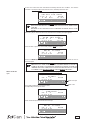
MANAGING THE FILES BY DATAFLASH SW .................................................................................................................... 12
LAUNCHING THE PROGRAM ......................................................................................................................................12
DIALOGUE WITH THE DEVICE .....................................................................................................................................12
SAVING THE REPORT FILE ..........................................................................................................................................13
REPORT FILE MANAGEMENT......................................................................................................................................13
FILE NAME .................................................................................................................................................................... 14
FILES VISUALIZATION .................................................................................................................................................. 14
CONNECTING AN EXTERNAL WATER FILLING TANK .....................................................................................................15
DIRECT CONNECTION TO A CENTRALIZED DRAINING POINT ......................................................................................16
FIRST START-UP ................................................................................................................................. 17
TURNING ON THE EQUIPMENT ........................................................................................................................................ 17
INITIAL AUTOMATIC TEST ................................................................................................................................................. 17
ACQUISITION AND UPDATING OF THE AMBIENT PRESSURE VALUES .........................................................................17
STAND-BY MODE ...............................................................................................................................................................18
FILLING DISTILLED WATER ..............................................................................................................................................19
MANUAL FILLING (TOP SIDE) ......................................................................................................................................19
MANUAL FILLING (FRONT SIDE) .................................................................................................................................19
AUTOMATIC FILLING....................................................................................................................................................20
MAX LEVEL IN THE INTERNAL / EXTERNAL DRAIN TANK .............................................................................................. 20
EMPTYING THE USED WATER INTERNAL TANK ........................................................................................................20
DETACHING THE PIPE .................................................................................................................................................20
CONFIGURATION ...............................................................................................................................21
INTRODUCTION .................................................................................................................................................................21
STARTING AND ENTERING THE SETUP MODE ...............................................................................................................21
MEANING OF THE KEYS IN SETUP MODE ....................................................................................................................... 21
DESCRIPTION OF THE MENU ITEMS ...............................................................................................................................23
DEFAULTS SETTINGS ........................................................................................................................................................ 25
ACTIVATING CONFIGURATION OPTIONS ......................................................................................................................... 25

SETTING THE LANGUAGE ........................................................................................................................................... 25
(LANGUAGE ON THE BASIC MENU) ...........................................................................................................................25
SETTING THE DATE ......................................................................................................................................................25
SETTING THE TIME ......................................................................................................................................................26
SETTING THE PASSWORD ..........................................................................................................................................26
SETTING THE STERILIZATION PROGRAMS ...............................................................................................................27
SETTING THE STAND-BY MODE .................................................................................................................................31
SETTING THE PRINTING MODE ..................................................................................................................................32
SETTING THE TANK FILLING MODE ...........................................................................................................................34
ACQUISITION OF THE AMBIENT PRESSURE .............................................................................................................35
ADJUSTING THE CONTRAST OF THE LIQUID CRYSTAL DISPLAY ............................................................................36
EXIT THE CONFIGURATION MODE ................................................................................................................................... 36
PREPARING THE MATERIAL .............................................................................................................37
INTRODUCTION .................................................................................................................................................................37
TREATING TEXTILE MATERIAL BEFORE STERILIZATION ................................................................................................37
TREATING THE LOAD BEFORE STERILIZATION ............................................................................................................... 37
ARRANGING THE LOAD ....................................................................................................................................................38
STERILIZATION MONITORING...........................................................................................................................................39
PROGRAM ...........................................................................................................................................40
SELECTION .........................................................................................................................................40
INTRODUCTION .................................................................................................................................................................40
PROCEDURE ...................................................................................................................................................................... 40
RUNNING THE CYCLE .......................................................................................................................42
INTRODUCTION .................................................................................................................................................................42
STARTING THE CYCLE ......................................................................................................................................................42
PROGRAM EXECUTION .....................................................................................................................................................43
RESULT OF THE CYCLE ....................................................................................................................................................47
CHECK OF THE CYCLE DATA REPORT ...........................................................................................................................48
STORING DATA ON THE USB KEY .................................................................................................................................... 48
MANUAL CYCLE INTERRUPTION .....................................................................................................................................48
STORING STERILIZED MATERIALS..................................................................................................50
INTRODUCTION .................................................................................................................................................................50
HANDLING ..........................................................................................................................................................................50
STORAGE ...........................................................................................................................................................................50
TEST PROGRAMS ..............................................................................................................................51
INTRODUCTION .................................................................................................................................................................51
HELIX/BD TEST ..................................................................................................................................................................51
VACUUM TEST ................................................................................................................................................................... 52
APPENDIX A – TECHNICAL CHARACTERISTICS ............................................................................ 55
SUMMARY TABLE .............................................................................................................................................................. 55
SAFETY DEVICES ...............................................................................................................................................................56
WATER SUPPLY CHARACTERISTICS ................................................................................................................................57
APPENDIX B – PROGRAMS ...............................................................................................................58
INTRODUCTION .................................................................................................................................................................58
PROGRAM SUMMARY TABLE ........................................................................................................................................... 59
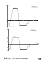
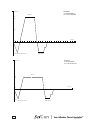
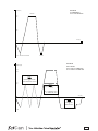
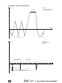
DIAGRAMS OF THE TEST PROGRAMMES ....................................................................................................................... 66
EXAMPLES OF PRINTED REPORTS .................................................................................................................................. 67
APPENDIX C – MAINTENANCE .........................................................................................................69
INTRODUCTION .................................................................................................................................................................69
ROUTINE MAINTENANCE ..................................................................................................................................................69
SCHEDULED MAINTENANCE MESSAGES .................................................................................................................69
III

BRAVO and Your Infection Control Specialist are a trademarks of
SciCan Ltd. All other trademarks referred to in this manual are the
property of their respective owners.
Manufactured by:
SciCan Ltd.
1440 Don Mills Road,
Toronto ON M3B 3P9
CANADA
Phone: +1-416-445-1600
Fax: +1-416-445-2727
Toll free: 1-800-667-7733
0123
SciCan Inc.
701 Technology Drive
Canonsburg, PA 15317
USA
Phone: 724-820-1600
Toll Free: 1-800-572-1211
Fax: 724-820-1479
SciCan Medtech
Alpenstrasse 16
6300 Zug, Switzerland
Tel: +41 (0) 41-727-7027
Fax: +41 (0) 41-727-7029
EC Representative
SciCan GmbH
Wangener Strasse 78
88299 Leutkirch
GERMANY
Tel.: +49 (0) 7561-98343-0
Fax: +49 (0) 7561-98343-699
For all service and repair inquiries
Canada: 1-800-870-7777
United States: 1-800-572-1211
EU +49 (0) 7561 98343-641
International +1 (416) 445-1600
[email protected] (USA)
[email protected] (International)
IV
IV
MAINTENANCE DESCRIPTION .........................................................................................................................................71
CLEAN GASKET AND PORTHOLE ..............................................................................................................................71
TO REMOVE ANY TRACES OF LIME ...........................................................................................................................71
CLEAN EXTERNAL SURFACES ....................................................................................................................................71
CLEAN STERILIZATION CHAMBER AND ACCESSORIES ..........................................................................................71
DISINFECT EXTERNAL SURFACES .............................................................................................................................71
CLEANING THE INTERNAL TANK ................................................................................................................................72
CLEAN EXTERNAL DISTILLED WATER TANK .............................................................................................................. 72
SAFETY VALVE MAINTENANCE .................................................................................................................................. 72
CLEAN/REPLACE THE DRAIN FILTER .........................................................................................................................73
REPLACE BACTERIOLOGICAL FILTER ........................................................................................................................73
REPLACING THE PRINTER PAPER ............................................................................................................................. 73
PERIODIC STERILIZER MAINTENANCE (EVERY 3000 CYCLES) ......................................................................................74
APPENDIX D – TROUBLESHOOTING ...............................................................................................75
INTRODUCTION .................................................................................................................................................................75
ANALYSIS AND RESOLUTION OF PROBLEMS.................................................................................................................75
APPENDIX E – ALARMS ..................................................................................................................... 78
INTRODUCTION .................................................................................................................................................................78
ALARM INTERVENTION .....................................................................................................................................................78
ALARM DURING A CYCLE ...........................................................................................................................................78
ALARM OUTSIDE THE CYCLE ....................................................................................................................................79
RESETTING THE SYSTEM ................................................................................................................................................80
ALARM CODES ..................................................................................................................................................................81
ANALYSIS AND RESOLUTION OF PROBLEMS.................................................................................................................83
APPENDIX F – NOTES FOR THE OPERATOR ..................................................................................89
APPENDIX G – TECHNICAL SUPPORT ............................................................................................90
APPENDIX H – LIMITED WARRANTY ...............................................................................................91

1
Congratulations on your selection of the Bravo™ Autoclave. We are con dent that you have
purchased the nest equipment of its type. The Bravo is a counter-top unit that features a
number of sterilizing cycles designed to meet your needs and suitability for steam sterilization.
The details of installing, operating and maintaining your Bravo are all contained within this
operator’s manual. To ensure years of safe, trouble-free service please read these instructions
before operating this unit and keep them for future reference. Operational, maintenance and
replacement instructions should be followed for the product to perform as designed. Contents
of this manual are subject to change without notice to re ect changes and improvements to the
Bravo product.
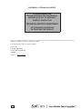
NOTE
this symbol indiCates important information.
WARNING
THIS SYMBOL INDICATES A POTENTIAL DANGER OF INJURY. FOLLOW THE PRO-
CEDURES DESCRIBED IN THE MANUAL TO AVOID INJURING THE USER AND/OR
OTHERS.
DANGER
THIS SYMBOL INDICATES A POTENTIAL DANGER OF PROPERTY DAMAGE. FOL-
LOWS THE INSTRUCTIONS IN THE MANUAL TO PREVENT POTENTIAL DAMAGE TO
MATERIALS, EQUIPMENT OR OTHER PROPERTY.
DANGER
THIS SYMBOL INDICATES A POTENTIAL DANGER DUE TO HIGH TEMPERATURE.
THE MATERIAL THE STERILIZER IS COMPOSED OF MUST BE DISPOSED ACCOR-
DING TO THE DIRECTIVE 2002/96/CEE.
Potenzial hazard due to high temperature.
Equipment in accordance with applicable directives.
Symbol for disposal in accordante with Directive 2002/95 EC, 2002/96/ EC,
and 2003/108/ EC.
Consult the user manual.
The Bravo units described in this manual are to be used exclusively for the sterilization of solid
and hollow re-usable instruments and porous materials (e.g., textiles).
WARNING
THE DEVICE MUST ONLY BE USED BY QUALIFIED PERSONNEL. IT MAY
NOT BE USED OR HANDLED BY INEXPERT AND/OR UNAUTHORIZED
PERSONNEL FOR ANY REASON.
THIS DEVICE MUST NOT BE USED FOR THE STERILIZATION OF FLUIDS,
LIQUIDS OR PHARMACEUTICAL PRODUCTS.
Do not permit any person other than certi ed personnel to supply parts for, service or maintain
your Bravo. SciCan shall not be liable for incidental, special or consequential damages caused by
any maintenance or services performed on the Bravo by a third party, or for the use of equipment
or parts manufactured by a third party, including lost pro ts, any commercial loss, economic
loss, or loss arising from personal injury.
Never remove the cover of the unit and never insert objects through holes or openings in the
cabinetry. Doing so may damage the unit and / or pose a hazard to the operator.
All elements of this book are common to Bravo17, Bravo17V and Bravo21V, except where noted.
DISCLAIMERS
SYMBOLS ON
EQUIPMENT
SYMBOLS USED
IN THE MANUAL
INTRODUCTION

2
Please observe the following precautions in order to avoid injury or property damage:
– Use ONLY distilled water of high quality.
WARNING
THE USE OF WATER OF INADEQUATE QUALITY CAN SEVERELY DAMAGE
THE DEVICE.
SEE APPENDIX A, TECHNICAL CHARACTERISTICS IN THIS REGARD.
– Do not pour water or other liquids on the device;
– Do not pour inammable substances on the device;
– Do not use the device in the presence of gas or explosive or inammable vapors;
– Before performing any maintenance or cleaning, ALWAYS DISCONNECT the electricity.
WARNING
WHENEVER IT IS NOT POSSIBLE TO DISCONNECT THE ELECTRICITY TO
THE DEVICE, OR IF THE EXTERNAL POWER GRID SWITCH IS FAR AWAY
OR, AT ANY RATE, NOT VISIBLE TO THE MAINTAINER, PLACE A WORK
IN PROGRESS SIGN ON THE EXTERNAL POWER GRID SWITCH AFTER
TURNING IT OFF .
– Make sure the electrical system is grounded conforming to current laws and/or standards;
– Do not remove any label or nameplate from the device; request new ones, if necessary;
– Use only original replacement parts.
WARNING
THE FAILURE TO OBSERVE THE ABOVE, RELEASES THE MANUFACTU-
RER FROM ALL LIABILITY.
GENERAL WARNINGS

3
2
3
4
6
8
11
12
14 - 15
13
10
7
5
1
9
16
17
18
19
B
A
C
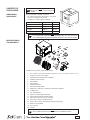
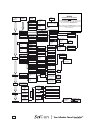
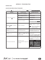
NOTE
CheCk the integrity of the paCkage upon
reCeipt.
Once the package is opened, check that:
– the content matches the specications of the order
(see the accompanying document);
– that there is no obvious product damage;
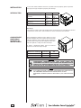
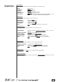
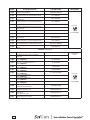
Dimensions and weight 17 and 17V 21V
A. Height 600 mm 600 mm
B. Width 580 mm 580 mm
C. Depth 700 mm 800 mm
Total weight 62 kg 68 kg
NOTE
if you have reCeived the wrong produCt, are missing parts, or if your unit has any
type of damage, immediately provide a detailed desCription to the seller and shipper.
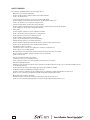
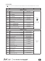
In addition to the steriliser, the package contains:
1. No. 3 stainless steel wire instrument tray
(BRAVO 17 includes 3 trays, BRAVO 17V/21V includes 5 trays);
2. Stainless steel wire tray support;
3. Operating documentation (with CD-ROM);
4. USB key for data storage;
5. Exhaust lter;
6. Tray extractor;
7. Water lling funnel;
8. Extra bacteriological lter;
9. Rubber hose with quick-coupling for manual water drainage;
10. 4 rubber caps;
11. 1/8” angular tting;
12. Spare roll of printer paper (optional);
13. Plastic tube with tting (automatic lling);
14. Allen wrench (3mm for rear cap removal);
15. Allen wrench (5mm for handle removal);
16. Plastic tube for direct water drainage with fastening clamp;
17. Bottle for manual lling;
18. No. 2 spacers;
19. Syringe.
NOTE
the Customer must keep the purChase reCeipt for any warranty serviCe.
DIMENSIONS
AND WEIGHT
DESCRIPTION OF
THE CONTENTS
CONTENTS OF
THE PACKAGE

4
Where possible, the packaged product must be handled using suitable mechanical means
(forklift truck, transpallet, etc.) and following the instructions shown on the package.
In the case of manual handling, the product must be lifted by two persons using the handles cut
in the side of the box.
Once taken out of the box, the sterilizer must be lifted by two persons and transported on a lift
truck or similar means.
WARNING
WE RECOMMEND THAT THE DEVICE BE TRANSPORTED AND STORED
AT A TEMPERATURE NO LOWER THAN 5 °C. PROLONGED EXPOSURE TO
LOW TEMPERATURE AN DAMAGE THE PRODUCT.
NOTE
keep the original paCkaging and use it whenever the deviCe is to be transported. the
use of different paCkaging Could damage the produCt during shipment.
DANGER
BEFORE TRANSPORT, LEAVE THE DEVICE TURNED-OFF FOR ABOUT 30
MINUTES AFTER THE LAST PROGRAM FINISHES AND DRAIN THE DISTIL-
LED WATER AND USED WATER TANKS SO THAT THE ALL THE HOT INTER-
NAL PARTS WILL HAVE TIME TO COOL.
HANDLING THE
PRODUCT
CAP REMOVAL
FROM THE TANK
BREATHER HOLE
(IF NECESSARY)
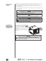
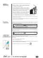
There may be a cap on the breather hole. If
present, the protection cap must ALWAYS
be removed from the breather hole of the
distilled water tank before starting the
sterilizer.
Use the Allen wrench provided with the
device and follow the procedure shown in
the gure.
WARNING
FAILURE TO REMOVE THE CAP MAY CAUSE THE DEVICE NOT TO WORK
PROPERLY AND ITS INTERIOR COMPONENTS BEING DAMAGED.
MAKE SURE YOU FOLLOW THE PROCEDURE DESCRIBED ABOVE BEFO-
RE INSTALLING THE DEVICE.

5
Bravo is SciCan's revolutionary chamber autoclave designed with safety, performance, exibility
and ease of use in mind.
It is a sophisticated yet easy-to-use sterilizer with a wide range of conguration options and
patented operating devices designed to satisfy every need for sterilizing medical and dental
tools, guaranteeing the maximum performance under all conditions.
Easy-to-use, compact and aesthetically pleasing, Bravo is the ideal partner for professionals
seeking maximum sterilization safety.
PRODUCT
OVERVIEW
GENERAL
CHARACTERISTICS
Bravo is a microprocessor-controlled steam sterilizer with a large sterilization chamber made of
stamped stainless steel.
It is characterized by an advanced fractionated vacuum system for the complete removal of
air from hollow and porous materials, and an effective nal vacuum drying phase capable of
effective drying of these loads.
Its exclusive steam generation system, effective plumbing circuit and electronic management
(supplemented by high-precision sensors) guarantees high process execution speeds and
excellent thermodynamic parameter stability. Moreover, its Process Evaluation System
constantly monitors all the machine's vital parameters in real-time, guaranteeing absolute safety
and perfect results.
It offers users 10 sterilization programs (one customizable), each equipped with optimized drying
for the fast, effective sterilization of the various types of loads (instruments and materials) used
in a medical or dental environment. The custom programs have not been validated and have not
been cleared in the U.S. by FDA for healthcare use.
Bravo units also offer a number of interesting options for conguring the preheating mode (based
on the sterilizer's frequency of use) and printing the cycle report (printer optional on Bravo17).
Bravo sterilizers also have one of the most complete, sophisticated and advanced safety systems
available today to protect users in the case of electrical, mechanical, or thermal operating
anomaly.
NOTE
please refer to appendex a (teChniCal CharaCteristiCs) for a desCription of bravo's
unintegrated safety deviCes.

6
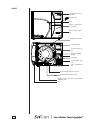
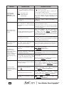
FRONT
LCD display and con-
trol panel
Sterilization chamber
Door
Door microswitch
Service compartment
access panel
Bacteriological lter
Printer paper output
slot
USB port
Exhaust lter
Encased printer (op-
tional)
Service compartment
open
On/Off switch
Motorized closing sy-
stem
Used water drain quick connector
Distilled water ll quick connect
Door
Distilled water tank drain quickcoupling
(SERVICE only)

7
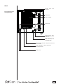
REAR
Distilled water tank
vent hole
Heat exchanger
Safety valve
Connection for auto-
matic loading of the
load tank
Connection for di-
rectly draining the
used water tank
Band heating element safety thermostat and
manual rearm
Power cord
Steam generator safety thermostat
and manual rearm
Mains fuses
Version with automatic
loading with pump

8
-
+
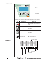
CONTROL PANEL
LCD DISPLAY
Liquid Crystal Display
(LCD)
Command keys
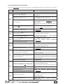
The function of the command keys differ according to operating mode of the equipment.
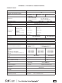
Key NORMAL mode SETUP mode
Cycle Start/Stop
Enter, con rmation of the value/option se-
lected
+
+
+
+
+
+
+
+
+
+
+
+
Sterilization cycle selection
Value increment / Forward scroll of the
menu options
-
-
-
-
Test cycle selection
Value decrement / Backward scroll of the
menu options
Enter Setup mode ESC, quit the current menu
Alarm
Setup status
Process status
Port status
Water level
4 lines of 20 characters
Illuminated icon

9
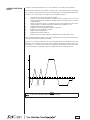
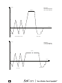
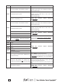
The Bravo’s sterilization program is a succession of phases, each with a specic purpose.
After loading the material in the chamber, closing the door, selecting the program and starting
the cycle (the door opening mechanism locks automatically), the standard program (for porous
materials, 134 °C at 4 minutes, for example) uses the following sequence:
1. Preheats the generator and sterilization chamber;
2. Removes the air and penetrates the material by steam through a series of vacuum
(extracting uid from the sterilization chamber) and pressure (injecting steam into the
chamber) phases;
3. Raises the pressure, with the consequent increase in the temperature of the steam,
until reaching the conditions required for sterilization (for example, 134 °C);
4. Stabilizes the pressure and temperature;
5. Sterilizes for the required time (for example, 4 minutes);
6. Depressurizes the sterilization chamber;
7. Begins vacuum-drying phase;
8. Ventilates the load with sterile air;
9. Brings the pressure of the sterilization chamber back to the atmospheric level.
After reaching atmospheric pressure, the door is automatically unlocked and can be opened to
remove the load from the sterilization chamber.
Phases 1, 3, 4, 6 and 9 are identical in all cycles, with slight variations of duration that are solely
dependent on the quantity and consistency of the load and the heating conditions of the steri-
lizer. Phases 2, 5, 7 and 8, however, vary their conguration and/or duration on the basis of the
cycle selected (and, consequently, the type of load) and the choices made by the user.
NOTE
please refer to appendix b (programs) for more detail.
SAMPLE OPERATING
CYCLE
0.00
1.00
2.00
2.10
Pres sure (bar)
Time (
min)
VACUUM DRYING
PR OC ESS
SINGLE VACUUM PULSE
-0.80

10
A
C
B
C
B
A
Correct and careful installation will ensure your Bravo functions properly, protects operators
from physical injury and protects property from damage.
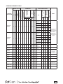
Dimensions and weight 17 and 17V 21V
A. Height (total, excluding
handles)
420 mm /
16.5"
420 mm /
16.5"
B. Width (total)
480 mm /
19"
480 mm /
19"
C. Depth (excluding rear con-
nections)
560 mm /
22.0"
660 mm /
25.0"
Total weight
58 kg / 128
lbs
63 kg /
139 lbs
Electricity
The electrical system to which the sterilizer will be connected must accommodate the electrical
characteristics of this device. This information is shown on the back of the machine.
When installing the sterilizer inside a cabinet, you must
provide adequate space all around the device to provide
effective ventilation. There should also be an opening in
the back large enough to provide adequate air ow. This
will allow optimum cooling of the heat exchanger.
A built-in compartment MUST have the minimum
dimensions shown in the gure at right.
Dimensions and weight 17 and 17V 21V
A. Height (total) 500 mm / 20" 500 mm / 20"
B. Width (total) 600 mm / 24" 600 mm / 24"
C. Depth 600 mm / 24" 700 mm / 28"
WARNING
COMPARTMENT DIMENSIONS LESS THAN THOSE SHOWN MAY
COMPROMISE THE CORRECT CIRCULATION OF AIR AROUND THE DEVICE
AND MAY NOT PROVIDE ADEQUATE COOLING. THIS CAN RESULT IN THE
DETERIORATION OF PERFORMANCE AND/OR POSSIBLE DAMAGE.
NOTE
do not remove the upper Cover or any other external part. when installed in
the Compartment, the deviCe must be Complete with all its parts.
please refer to appendix a (teChniCal CharaCteristiCs) for Complete teChniCal
data.
INSTALLATION
INTRODUCTION
COMPARTMENT
DIMENSIONS
FOR BUILT-IN
INSTALLATIONS

11
To ensure operator safety and the correct performance of the device:
GENERAL
INSTALLATION
PRECAUTIONS
ELECTRICAL
CONNECTIONS
CONNECTION OF
USB PEN DRIVE
RECORDING DEVICE
– Install the sterilizer on a at level surface strong enough
to support the device's weight, and use the leveling feet to
compensate for an irregular surface;
– Leave adequate space for ventilation, at least 2" (50 mm) on
both sides and top and 4" (100 mm) at the back, using the
spacers supplied in the toolkit. If the device is installed in a
cabinet, be sure to respect the warnings in the preceding
paragraph, avoiding any obstructions to the air intake;
– Avoid contact with liquids. Do not install the sterilizer near
tubs, sinks or similar places, as this could cause short circuits
and/or potentially dangerous situations for the operator;
– Do not install the sterilizer in a place that is excessively humid or poorly ventilated;
– Do not install the machine were there is gas or ammable and/or explosive vapors;
– Install the device so that the power cord is not sharply bent or kinked. It must run freely to the
electrical connection socket;
– Install the device so that any external ll/drain tubing(s) is/are not sharply bent or kinked.
These must run freely to the drain tank.
The Bravo must be connected to an outlet that provides adequate capacity for the device's
absorption and ground, and which conforms with current laws and/or standards. The outlet must
also be protected by suitable breaker.
WARNING
THE MANUFACTURER WILL NOT BE LIABLE FOR DAMAGES CAUSED BY
INSTALLING THE STERILIZER ON AN INADEQUATE ELECTRICAL SYSTEM
AND/OR NOT EQUIPPED WITH A GROUND.
If it is necessary to replace the plug on the power cord, use one with equal characteristics or,
at any rate, adequate to the device's electrical characteristics. The user is entirely responsible
for the selection and replacement of the plug. This replacement should only be performed by a
trained service professional.
NOTE
always ConneCt the power Cord direCtly to the soCket. do not use extension
Cords, adapters or other aCCessories.
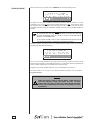
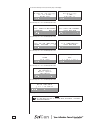
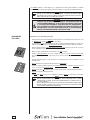
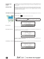
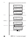
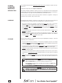
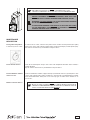
The recorded DATA can be copied, read and printed using DataFlash software installed on a
compatible personal computer that is tted with a USB port.
Installation of the DataFlash software stored on the CD-rom and attached to the operating
documentation.
– Insert the cd-rom into the CD drive of the PC.
– Click on “setup_DataFlash [rev]”.
– Follow the installation instructions that appear on the display. During installation, a "DataFlash"
folder is created which contains the necessary les.
– In addition, a programme icon is created on the PC's desktop.

12
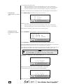
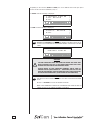
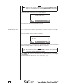
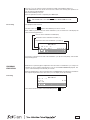
DataFlash software is a programme for Windows (versions 98, XP, and Vista) that allows users to
download data contained in the USB key to the PC and then and process that data.
Launch the DataFlash program from its desktop icon, or select the executable program
le.
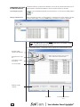
After launching the program, a window appears containing the le reports folder (on the rst
launch it will be empty). Click on the “USB” button to enable the connection to DataFlash.
note
the usb key must be ConneCted to the pC when the programme is started
otherwise an error message will appear.
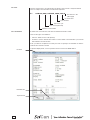
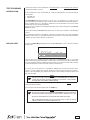
A second window appears, containing the le list related to the stored sterilization cycles.
MANAGING THE FILES
BY DATAFLASH SW
Launching the program
Dialogue with the device
Reading of data
stored on the USB key
Saving the les on the
PC.
Cancellation of USB
key memory
List of stored les
Percentage of used me-
mory
NOTE: the keys functions are also pre-
sent as sub-menus in the menu bar
Status bar
USB key storage
capacity

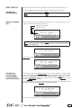
13
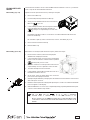
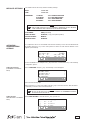
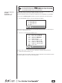
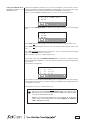
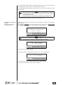
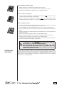
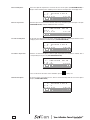
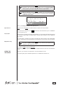
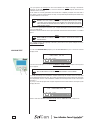
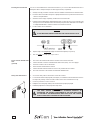
Saving the Report fi le
Report fi le management
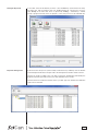
To save les stored on the USB key to the PC, select the Save key (or File-Save from menu).
The three keys and the window menu are disabled during the save process; the mes-
sage “Ready” in the status bar shows is replaced by “Saving...”, followed by a number
and by a progress bar that shows the progress of the save process for the individual les.
At the end of the save process (status “Ready” and function keys enabled), close the window
for the dialogue with the device and proceed to the management of the les saved on the PC.
The les are saved according to the cycle date in a directory automatically generated by the
program and made up of folders for the years and subfolders for the months.
The les names are assigned on the basis of the cycle data, type, size and date of modi cation
of les are also included.

14
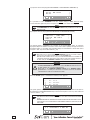
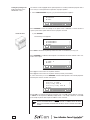
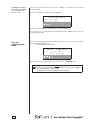
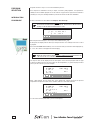
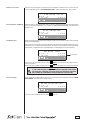
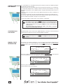
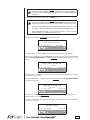
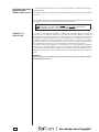
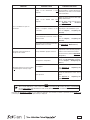
The les saved on the PC are named “Mocom register”. Each new le is assigned a default
name according to the information included in the original le:
Es.: 12JM1234_00001_134PRION_190406_1024.dtl
File extension “.dtl”
(data logger)
Cycle start time
Cycle start date
Type of the cycle
Cycle counter (launched)
Sterilizer's serial number
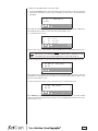
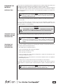
A double click on the le name, will show the window with the le content.
There are two types of visualization:
– reduced - default, shown on le opening;
– extended – click the “Extend view” button to see the details of the sterilization cycle, with all
data omitted in the reduced view.
If the cycle did not completed successfully, the view on opening is the extended one and the
reduced view cannot be selected.
To print the displayed le, connect a printer to the PC and click the “Print” button.
File name
Files visualization
File name
To print the le
Extended view

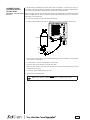
15
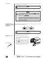
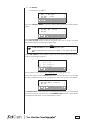
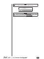
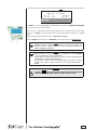
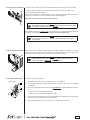
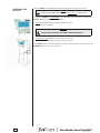
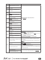
To avoid having to regularly ll the internal water tank (see Chapter 5 - Instructions for Use), it is
possible to connect the sterilizer to an optional external tank that the user will less frequently ll, or
to a commercially-available, water purication system with accumulation tank.
With this option, the autoclave automatically activates a pump that lls the internal tank when it
reaches the MIN level. Be sure to monitor the external tank as the Bravo unit can not monitor the
water level in the external tank.
To connect the external tank, follow the instructions below:
– Install the tap provided on the tank; use Teon tape or connector sealant for a perfect seal.
Clip
Silicon pipe
Teflon
Tap
Clip
Filling tank
– Use the tank’s silicone tube (or other suitable tube) and insert it on the lling connector taking
care to push it completely on.
– Lock the tube to connector with the plastic tie provided.
– Insert the other end of the tube on the tap of the tank.
– Make sure that the tube runs freely from the device to the tank, without being bent, crushed
or obstructed in any way.
– Loosen the cap to facilitate the ow of water.
– Open the tap on the lling tank.
NOTE
refer to the Chapter — Configuring the deviCe - automatiC filling option.
CONNECTING AN
EXTERNAL WATER
FILLING TANK
(OPTIONAL, automatic filling
function)

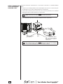
16
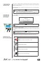
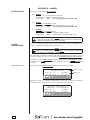
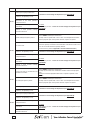
Follow the instructions shown below for a correct direct connection to a centralized draining
point:
– Insert the silicone tube (provided) or other suitable plastic tube onto hose connection A; push
the tube all the way on and lock with the plastic tie or other means;
– Cut the tube to measure, push the free end on the connection provided on the centralized
draining point and lock with the plastic tie or other means.
NOTE
make sure the tube is not bent, Crushed or obstruCted in any way.
The following diagram provides an indicative arrangement of the components:
NOTE
the ConneCtion point to the Central drain must be lower than the sterilizer's
support surfaCe. otherwise, the tank may not empty CorreCtly.
DIRECT CONNECTION
TO A CENTRALIZED
DRAINING POINT
Support
plane
Pipe
Connector (A)
This point must be at level
lower than the sterilizer's
support plane
To the centralized
draining point
Drain siphon
Clamp
La pagina si sta caricando...
La pagina si sta caricando...
La pagina si sta caricando...
La pagina si sta caricando...
La pagina si sta caricando...
La pagina si sta caricando...
La pagina si sta caricando...
La pagina si sta caricando...
La pagina si sta caricando...
La pagina si sta caricando...
La pagina si sta caricando...
La pagina si sta caricando...
La pagina si sta caricando...
La pagina si sta caricando...
La pagina si sta caricando...
La pagina si sta caricando...
La pagina si sta caricando...
La pagina si sta caricando...
La pagina si sta caricando...
La pagina si sta caricando...
La pagina si sta caricando...
La pagina si sta caricando...
La pagina si sta caricando...
La pagina si sta caricando...
La pagina si sta caricando...
La pagina si sta caricando...
La pagina si sta caricando...
La pagina si sta caricando...
La pagina si sta caricando...
La pagina si sta caricando...
La pagina si sta caricando...
La pagina si sta caricando...
La pagina si sta caricando...
La pagina si sta caricando...
La pagina si sta caricando...
La pagina si sta caricando...
La pagina si sta caricando...
La pagina si sta caricando...
La pagina si sta caricando...
La pagina si sta caricando...
La pagina si sta caricando...
La pagina si sta caricando...
La pagina si sta caricando...
La pagina si sta caricando...
La pagina si sta caricando...
La pagina si sta caricando...
La pagina si sta caricando...
La pagina si sta caricando...
La pagina si sta caricando...
La pagina si sta caricando...
La pagina si sta caricando...
La pagina si sta caricando...
La pagina si sta caricando...
La pagina si sta caricando...
La pagina si sta caricando...
La pagina si sta caricando...
La pagina si sta caricando...
La pagina si sta caricando...
La pagina si sta caricando...
La pagina si sta caricando...
La pagina si sta caricando...
La pagina si sta caricando...
La pagina si sta caricando...
La pagina si sta caricando...
La pagina si sta caricando...
La pagina si sta caricando...
La pagina si sta caricando...
La pagina si sta caricando...
La pagina si sta caricando...
La pagina si sta caricando...
La pagina si sta caricando...
La pagina si sta caricando...
La pagina si sta caricando...
La pagina si sta caricando...
La pagina si sta caricando...
-
 1
1
-
 2
2
-
 3
3
-
 4
4
-
 5
5
-
 6
6
-
 7
7
-
 8
8
-
 9
9
-
 10
10
-
 11
11
-
 12
12
-
 13
13
-
 14
14
-
 15
15
-
 16
16
-
 17
17
-
 18
18
-
 19
19
-
 20
20
-
 21
21
-
 22
22
-
 23
23
-
 24
24
-
 25
25
-
 26
26
-
 27
27
-
 28
28
-
 29
29
-
 30
30
-
 31
31
-
 32
32
-
 33
33
-
 34
34
-
 35
35
-
 36
36
-
 37
37
-
 38
38
-
 39
39
-
 40
40
-
 41
41
-
 42
42
-
 43
43
-
 44
44
-
 45
45
-
 46
46
-
 47
47
-
 48
48
-
 49
49
-
 50
50
-
 51
51
-
 52
52
-
 53
53
-
 54
54
-
 55
55
-
 56
56
-
 57
57
-
 58
58
-
 59
59
-
 60
60
-
 61
61
-
 62
62
-
 63
63
-
 64
64
-
 65
65
-
 66
66
-
 67
67
-
 68
68
-
 69
69
-
 70
70
-
 71
71
-
 72
72
-
 73
73
-
 74
74
-
 75
75
-
 76
76
-
 77
77
-
 78
78
-
 79
79
-
 80
80
-
 81
81
-
 82
82
-
 83
83
-
 84
84
-
 85
85
-
 86
86
-
 87
87
-
 88
88
-
 89
89
-
 90
90
-
 91
91
-
 92
92
-
 93
93
-
 94
94
-
 95
95


SciCan BRAVO 21V Manuale utente
- Tipo
- Manuale utente
in altre lingue
- English: SciCan BRAVO 21V User manual
Documenti correlati
Altri documenti
-
 MELAG MELAstore Istruzioni per l'uso
-
Berkel 250 Istruzioni per l'uso
-
Metos T2 8m3 Manuale del proprietario
-
MasterCool 69789-220 Istruzioni per l'uso
-
 Wabi Baby WA-8800N Manuale utente
-
Giacomini KHRA2-H Manuale utente
-
 Hologic CoolSeal Generator Guida utente
-
 Hologic CoolSeal Generator Guida utente
-
Chattanooga M2 Manuale utente
-


