Falmec Move Manuale utente
- Categoria
- Cappe da cucina
- Tipo
- Manuale utente
Questo manuale è adatto anche per

LIBRETTO ISTRUZIONI IT
INSTRUCTIONS BOOKLET EN
GEBRAUCHSANWEISUNG DE
MODE D'EMPLOI FR
MANUAL DE INSTRUCCIONES ES
ИНСТРУКЦИИ RU
INSTRUKCJA OBSŁUGI PL
HANDLEIDING NL
MANUAL DE INSTRUÇÕES PT
BRUGSANIVSNINGER DK
INSTRUKTIONSBOK SE
OHJEKIRJA FI
BRUKSANVISNING NO
INSTRUCTIONS BOOKLET
Move
Design

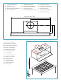
2
17 270
300 Q.Min.
48
340 Q.Max.
Q.Min.442 / Q.Max. 482
18
60 180
Q.Min. 195
Q.Max. 235
561 / 761 / 861 / 1161
105
303
73 264 56
150
Q.Min.13
Q.Max.53
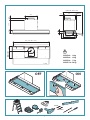
ø8 mm
ø6 mm
ONOFF
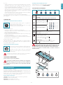
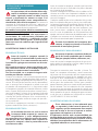
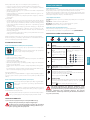
MOVE 60: 14 kg
MOVE 80: 16 kg
MOVE 90: 17 kg
MOVE 120: 20 kg

3
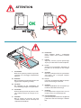
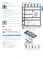
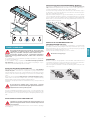
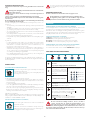
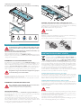
IT - ATTENZIONE!
Rimuovere la pellicola protettiva dal pannello
scorrevole, solo a montaggio completamente
eettuato.
EN - WARNING!
Only peel o the protective lm from the slid-
ing panel after completing assembly.
DE - ACHTUNG!
Die schutzfolie von der schiebeplatte erst
nach vollständig erfolgter montage abziehen.
FR - ATTENTION!
Enlever le lm protecteur du panneau coulis-
sant seulement lorsque le montage est ter-
miné.
ES - ATENCIÓN!
Quite la película de protección del panel
corredizo solamente cuando el montaje esté
completamente nalizado.
OK
ATTENTION
RU - ВНИМАНИЕ!
Снять защитную плёнку с раздвижной
панели только после полного монтажа
панели.
PL - UWAGA!
Zdjąć folię ochronną z panelu przesuwnego
dopiero po zakończeniu montażu urządzenia.
NL - LET OP!
Verwijder de beschermfolie uitsluitend aan
het einde van de montage van het schuifpa-
neel.
PT - ATENÇÃO!
Remover a película protetora do painel desliz-
ante, apenas com a montagem completa-
mente efetuada.
DK - PAS PÅ!
Fjern først den beskyttende lm fra skydepa-
nelet, når monteringen er afsluttet.
SE - VARNING!
Avlägsna skyddslmen från den skjutbara pa-
nelen först efter fullbordat montage.
FI - VAROITUS!
Irrota liukupaneelia suojaava kalvo vasta sit-
ten kun asennus on suoritettu loppuun.
NO - VÆR OPPMERKSOM!
Fjern den beskyttende lmen fra det glidende
panelet først etter at monteringen er helt full-
ført.

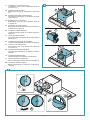
4
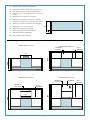
CABINET HEIGHT 360 mm
303
360
X
70
CABINET HEIGHT 480 mm
GLASS
OPTIONAL
OPTIONAL
KCVJN.01
305
480
CABINET HEIGHT 600 mm
GLASS
OPTIONAL
OPTIONAL
KCVJN.00
305
600
CABINET HEIGHT 720 mm
GLASS
OPTIONAL
OPTIONAL
KCVJN.00
720
OPTIONAL
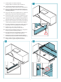
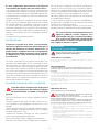
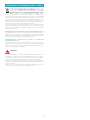
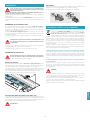
IT - Misura per il taglio della schiena del pensile.
EN - Cutting measurement to cut the suspended unit back.
DE - Maße zum Zuschneiden der Hängeschrankrückwand.
FR - Dimensions pour le découpage du panneau arrière du
meuble.
ES - Medida para el corte del trasero del colgante.
RU - Размер для резки задней стенки навесного шкафа.
PL -
Rozmiar wycięcia wykonywanego na tylnej płaszczyźnie szafki.
NL -
Afmeting voor de snede in de achterkant van het hangkastje.
PT - Medida para o corte do encosto do teto.
DK - Mål til formen på bagerste del af hylden.
SE - Mått för tillskärning av köksskåpets baksida.
FI - Keittiökaapin takaosan leikkuumitta.
NO - Mål for kutting av hyllens bakvegg.

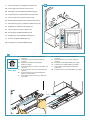
5
246
173
280 / 380 / 430 / 580
560 / 760 / 860 / 1160
520 mm
180 mm
165 mm
195 min
245 max
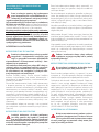
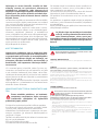
IT - Misure per l’installazione.
EN - Measurements for installation.
DE - Maßangaben für die Installation.
FR - Mesures pour l'installation.
ES - Medidas para la instalación.
RU - Размеры для установки.
PL - Środki montażowe.
NL - Maten voor de installatie.
PT - Medidas para a instalação.
DK - Mål for installation.
SE - Installationsåtgärder.
FI - Mitat asennusta varten.
NO - Installasjonsmål.
IT - Uscita alternativa posteriore
EN - Alternative rear outlet
DE - Alternativer Abzug auf der Ruckseite
FR - Sortie alternative arriere
ES - Salida alternativa posterior
RU - Дополнительный задний вывод
PL - Alternatywny tylny wylot
NL - Alternatieve uitgang op de achterkant
PT - Saida alternativa traseira
DK - Mulighed for bagudvendt aftrak
SE - Alternativt bakre uttag
FI - Vaihtoehtoinen takapoistumistie
NO - Alternativ bakre utgang

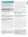
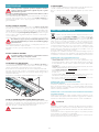
6
Ø2 mm
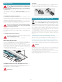
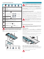
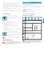
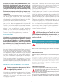
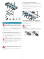
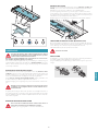
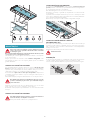
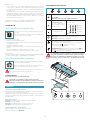
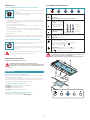
IT - Foratura pensile con le dime in dotazione(1),
Fissaggio sta e (2) e inserimento cappa nel pensile (3).
EN - Suspended unit drilling with supplied template (1),
Bracket fastening (2) and hood insertion in the suspended unit (3).
DE -
Anbringen der Bohrungen mit den enthaltenen Schablonen (1),
Befestigen der Halterungen (2) und Einsetzen der Abzugshaube
in den Hängeschrank (3).
FR - Perçage du meuble selon les gabarits fournis (1), Système de
xation (2) et pose de la hotte à l’intérieur du meuble (3).
ES -
Perforación del colgante con los patrones suministrados (1), Fija-
ción de los soportes (2) e inserción de la campana en el colgante (3).
RU -
Сверление навесного шкафа по входящим в комплект шаблонам (1),
Крепление кронштейнов (2) и установка вытяжки в навесной шкаф (3).
PL -
Wykonanie otworów w szafce za pomocą załączonych szablonów
(1), Mocowanie wsporników (2) i wsuwanie okapu w szafkę (3).
NL - Doorboring hangkastje met geleverde boormal (1), Bevesti-
ging beugels (2) en montage afzuigkap in het hangkastje.
PT - Perfuração teto com os moldes em dotação (1),
Fixação dos suportes (2) e inserção coifa no teto (3).
DK - Hyldens huller med medfølgende skabeloner (1), Fastgørelses-
beslag (2) og hættens indsætning i hylden (3).
SE - Borra hål i köksskåpet med de medföljande schablonerna (1)
Fäst byglarna (2) och för in spiskåpan i köksskåpet (3).
FI -
Keittiökaapin poraaminen varustuksiin kuuluvilla mallineilla (1).
Kannattimien (2) kiinnitys ja liesituulettimen asettaminen keittiökaappiin (3).
NO - Hulling av hyllen ved hjelp av medfølgende maler (1),
Festing av fester (2) og plassering av hetten i hyllen (3).
1
V1
V1
32

7
V2 (M4x20)
x4
360 mm
3
4
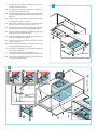
12
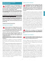
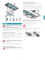
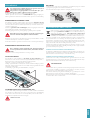
IT - Fissaggio cappa al pensile (4) centraggio camera motore e
inserimento sta e posteriori (5).
EN - Hood fastening to suspended unit (4) motor chamber cen-
tring and rear bracket insertion (5).
DE - Befestigen der Abzugshaube am Hängeschrank (4), Zentrie-
ren der Motorkammer und Einsetzen der rückseitigen Halte-
rungen (5).
FR - Fixation de la hotte au meuble (4) centrage chambre moteur
et xation aux ancrages postérieurs (5).
ES - Fijación de la campana al colgante (4), centrado de la cámara
del motor e inserción de los soportes posteriores (5).
RU - Крепление вытяжки к навесному шкафу (4), центровка
камеры двигателя и установка задних кронштейнов (5).
PL - Mocowanie okapu do szafki (4), wyśrodkowanie komory na
silnik i wsunięcie wsporników tylnych (5).
NL - Bevestiging afzuigkap aan hangkastje(4) centrering motor-
ruimte en montage beugels achter (5).
PT - Fixação coifa ao teto (4) centragem câmara motor e inserção
suportes posteriores (5).
DK - Hættens fastgørelse til hylden (4) centrering af motorrum-
met og indsætning af bagerste beslag (5).
SE - Fäst spiskåpan i köksskåpet (4), centrera motorrummet och
för in de bakre byglarna (5).
FI -
Liesituulettimen kiinnittäminen keittiökaappiin (4),
moottorikotelon keskitys ja takakannattimien asettaminen (5).
NO - Feste av hetten til hyllen (4) sentrering av motorkammeret
og plassering av bakre fester (5).
5
4

8
2
1
1
3
4
2
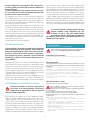
6
7
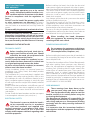
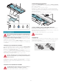
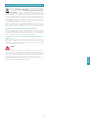
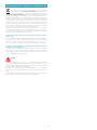
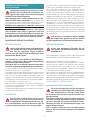
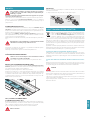
IT - Installazione con uscita verticale: Installazione valvola di non
ritorno (6), tubo di aspirazione e collegamento elettrico (7)
EN - Installation with vertical outlet: Installation of check valve
(6), suction pipe and electrical connection (7)
DE - Installation mit vertikalem Abzug: Installation des Rucksch-
lagventils (6), des Absaugrohrs und der elektrischen Verbin-
dung (7)
FR - Installation avec sortie verticale:Installation clapet de non
retour (6), tuyau d'aspiration et branchement electrique (7)
ES - Instalacion con salida vertical: Instalacion de la valvula de
no-retorno (6) tubo de aspiracion y conexion electrica (7)
RU - Установка с вертикальным выходом: Установка
обратного клапана (6), вытяжная труба подключение к
электрической сети (7)
PL - Montaż z wylotem pionowym: Instalacja zaworu zwrotnego
(6), przewodu zasysającego i podłączenia elektrycznego (7)
NL - Installatie met verticale uitgang: Installatie keerklep (6),
afzuigbuis en elektrische aansluiting (7)
PT - Instalacao com saida vertical: Instalacao da valvula de nao
retorno (6), tubo de aspiracao e ligacao eletrica (7)
DK - Installation med lodret aftrak: Installation af kontraventil (6),
ror til udsug og elektrisk tilslutning (7)
SE - Installation med vertikalt uttag: Installation av backventil
(6), utsugningsror samt elektrisk anslutning (7)
FI - Asennus pystysuuntaisella poistumistiella: Vastaventtiilin (6)
asennus, imuputki sahkoliitanta (7)
NO - Installasjon med vertikal utgang: Installasjon av tilbakeslag-
sventil (6), innsugingsror og elektrisk tilkobling (7)

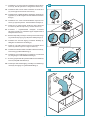
9
8
9
IT - Installazione con uscita posteriore:
spostamento uscita aria (8), installazione valvola di
non ritorno (9).
EN - Installation with rear outlet:
Output air movement (8), installation of check valve
(9).
DE - installation mit abzug auf der Ruckseite:
Versetzen des Luftausgangs (8), Installation des Ruck-
schlagventils (9).
FR - Installation avec sortie arriere:
Déplacement sortie d’air (8), installation clapet de
non retour (9).
ES - Instalacion con salida posterior:
Desplazamiento de la salida de aire (8), instalacion de
la valvula de no-retorno (9).
RU - Установки с задним выводом:
смещение выхода воздуха (8), Установка обратного
клапана (9).
PL - Instalacji z tylnym wylotem:
przesunięcie wylotu powietrza (8), instalacja zaworu
zwrotnego (9).
NL - Installatie met uitgang op de achterkant:
verplaatsing luchtuittrede (8), Installatie keerklep (9).
PT - Instalacao com saida posterior:
deslocamento saída ar (8), instalacao da valvula de
nao retorno (9).
DK - Installation med bagudvendt aftrak:
Forskydning af luftudtag (8), Installation af kontra-
ventil (9).
SE - Installation med bakre uttag:
Flytta luftutsläppet (8), installation av backventil (9).
FI - Takapoistumistien asentamiseksi:
ilman ulostuloaukon siirtäminen (8), vastaventtiilin (9).
NO - Installasjon med bakre utgang:
ytting av luftutgang (8), installasjon av tilbakeslag-
sventil (9).
x 8
x 8
180° 90°
1
34
6
2
5
1
3
4
2

10
F
2
1
10
IT - Tubo di aspirazione e collegamento elettrico (10)
EN - Suction pipe and electrical connection (10).
DE -
Absaugrohrs und der elektrischen Verbindung (10).
FR - Tuyau d'aspiration et branchement electrique (10).
ES - Tubo de aspiracion y conexion electrica (10).
RU -
Вытяжная труба подключение к электрической сети (10).
PL -
Przewodu zasysającego i podłączenia elektrycznego (10).
NL - Afzuigbuis en elektrische aansluiting (10).
PT - Tubo de aspiracao e ligacao eletrica (10).
DK - Ror til udsug og elektrisk tilslutning (10).
SE - Utsugningsror samt elektrisk anslutning (10).
FI - Asennus, imuputki sahkoliitanta (10).
NO - innsugingsror og elektrisk tilkobling (10).
OPTIONAL
KACL.961
2
1
1
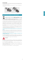
IT - Installazione ltro carbone-zeolite (KACL.961),
(opzionale)
EN - Installing the carbon-zeolite lter (KACL.961),
(optional)
DE - Installation des Kohlenstof-Zeolith-Filter
(KACL.961), (Option)
FR - Installation du ltres au charbon-zeolite (KACL.961),
(en option)
ES - Instalacion de ltros de carbon-zeolita (KACL.961),
(opcional)
RU - Установка или угольно-цеолитовый фильтр
(KACL.961), (опционально)
PL - Instalacja ltra węglowo-zeolitowego (KACL.961),
(opcjonalny)
NL - Installatie of zeoliet-/koolstolter (KACL.961),
(optioneel)
PT - Instalacao ltros de carvao-zeolito (KACL.961),
(opcional)
DK - Installation zeolit-kullteret (KACL.961), (valgfri)
SE - Installation kol-zeoltilter (KACL.961), (frivillig)
FI - Asennus Hiili-zeoliittisuodattimen (KACL.961),
(valinnainen)
NO - Installasjon karbon-zeolitt-lter (KACL.961), (valgfri)
11

11
ITALIANO
ISTRUZIONI DI SICUREZZA
E AVVERTENZE
Il lavoro d’installazione deve essere esegui-
to da installatori competenti e qualicati,
secondo quanto indicato nel presente li-
bretto e rispettando le norme in vigore.
Se il cavo di alimentazione o altri componenti
sono danneggiati, la cappa NON deve essere uti-
lizzata: staccare la cappa dall'alimentazione elettrica
e contattare il Rivenditore o un Centro Assistenza Tec-
nica autorizzato per la riparazione.
Non modicare la struttura elettrica, meccanica e
funzionale dell'apparecchiatura.
Non tentare di eettuare da soli riparazioni o so-
stituzioni: gli interventi eettuati da persone non
competenti e qualicate possono provocare dan-
ni, anche molto gravi, a cose e/o persone non co-
perti da garanzia del Costruttore.
AVVERTENZE PER L'INSTALLATORE
SICUREZZA TECNICA
Prima di installare la cappa controllare l'in-
tegrità e funzionalità di ogni sua parte: se
si notano anomalie non procedere nell'in-
stallazione e contattare il Rivenditore.
Nel caso sia stato riscontrato un difetto estetico la
cappa NON deve essere installata; riporla nel suo
imballo originale e contattare il Rivenditore.
Una volta installata non sarà accettato alcun re-
clamo per difetti estetici.
Durante l'installazione utilizzare sempre mezzi di pro-
tezione personale (es.: scarpe antiinfortunistiche) ed
adottare comportamenti prudenti e corretti.
Il kit di fissaggio (viti e tasselli) fornito con la cappa è
utilizzabile unicamente su pareti in muratura: in caso
di installazione su pareti di materiale diverso, valutare
altri sistemi di fissaggio tenendo conto della resisten-
za del muro e del peso della cappa (indicato a pag. 2).
Tenere presente che l’installazione con sistemi di fis-
saggio diversi da quelli forniti o non conformi può
comportare rischi di natura elettrica e di tenuta mec-
canica.
Non installare la cappa in ambienti esterni e non
esporla ad agenti atmosferici (pioggia, vento, ecc...).
SICUREZZA ELETTRICA
L’impianto elettrico al quale viene collega-
ta la cappa deve essere a norma e munito
di collegamento a terra secondo le norme
di sicurezza del Paese di utilizzo; deve essere inol-
tre conforme alle normative Europee sull’antidi-
sturbo radio.
Prima di installare la cappa verificare che la tensione
di rete corrisponda a quella riportata dalla targhetta
posta all’interno della cappa.
La presa usata per il collegamento elettrico deve es-
sere facilmente raggiungibile con l’apparecchiatura
installata: in caso contrario, prevedere un interruttore
generale per disconnettere la cappa al bisogno.
Ogni eventuale modifica all’impianto elettrico dovrà
essere eseguita solo da un elettricista qualificato.
La lunghezza massima della vite di fissaggio del cami-
no (fornita dal fabbricante) è di 13 mm. L'utilizzo di viti
non conformi con le presenti istruzioni può compor-
tare rischi di natura elettrica.
In caso di malfunzionamenti dell’apparecchio, non
tentare di risolvere da soli il problema, ma contatta-
re il Rivenditore o un Centro di Assistenza autorizzato
per la riparazione.
Durante l'installazione della cappa, disin-
serire l’apparecchio togliendo la spina o
agendo sull’interruttore generale.
SICUREZZA SCARICO FUMI
Non collegare l’apparecchio a condotti di
scarico dei fumi prodotti dalla combustio-
ne (ad es. caldaie, caminetti, ecc...)
Prima dell'installazione della cappa assicurarsi che si-
ano rispettate tutte le normative vigenti sullo scarico
dell’aria all’esterno del locale.
Deviazione per Australia e Nuova Zelanda: Le cap-
pe aspiranti e altri impianti di aspirazione di fumi da
cucina possono influire negativamente sul funziona-
mento in sicurezza degli elettrodomestici che brucia-
no gas o altri combustibili (anche se presenti in altre
stanze) a causa del ritorno dei gas di combustione,
che possono potenzialmente causare avvelenamen-
to da monossido di carbonio. Dopo l’installazione di
una cappa da cucina o di un altro impianto di aspi-
razione di fumi da cucina, il funzionamento degli
elettrodomestici a gas combusti deve essere testa-
to da una persona competente per garantire che
non si verifichi un ritorno dei gas di combustione.
(AS/NZS 60335.2.31:2013/A4:2020)
AVVERTENZE PER L'UTILIZZATORE
Queste avvertenze sono state redatte per
la vostra sicurezza e per quella degli altri, Vi
preghiamo, dunque, di leggere attenta-
mente questo libretto in tutte le sue parti prima
di utilizzare l’apparecchio o di eettuare opera-
zioni di pulizia sullo stesso.
Il Costruttore declina ogni responsabilità per
eventuali danni che possano, direttamente o in-
direttamente, essere causati a persone, cose ed

12
animali domestici conseguenti alla mancata os-
servanza delle avvertenze di sicurezza indicate in
questo libretto.
È molto importante che questo libretto istruzio-
ni sia conservato insieme all’apparecchiatura per
qualsiasi futura consultazione.
Se l’apparecchio dovesse essere venduto o trasferito
ad un’altra persona, assicurarsi che anche il libretto
venga fornito, in modo che il nuovo utente possa es-
sere messo al corrente del funzionamento della cap-
pa e delle avvertenze relative.
Dopo l’installazione delle cappe in acciaio inox è ne-
cessario eseguire la pulizia della stessa per rimuove-
re i residui di collante del protettivo e le eventuali
macchie di grasso e oli, che, se non rimosse, possono
causare il deterioramento irreversibile della superficie
della cappa. Per questa operazione il costruttore rac-
comanda l’utilizzo delle salviette in dotazione, dispo-
nibili anche in acquisto
Esigere parti di ricambio originali.
DESTINAZIONE D'USO
L’apparecchio è destinato solo ed esclusivamente
per l'aspirazione di fumi generati dalla cottura di
alimenti in ambito domestico, non professionale:
qualsiasi utilizzo diverso da questo è improprio,
può provocare danni a persone, cose ed animali
domestici e solleva il Costruttore da qualsiasi re-
sponsabilità.
L’apparecchio può essere utilizzato da bambini di età
non inferiore a 8 anni e da persone con ridotte capa-
cità fisiche, sensoriali o mentali, o prive di esperienza
o della necessaria conoscenza, purché sotto sorve-
glianza oppure dopo che le stesse abbiano ricevuto
istruzioni relative all’uso sicuro dell’apparecchio e alla
comprensione dei pericoli ad esso inerenti.
I bambini non devono giocare con l’apparecchio. La
pulizia e la manutenzione a cura dell’utilizzatore non
deve essere effettuata da bambini senza sorveglianza.
AVVERTENZE PER L'UTILIZZO E LA PULIZIA
Prima di procedere a qualsiasi operazione
di pulizia o di manutenzione, disinserire
l’apparecchio togliendo la spina o agendo
sull’interruttore generale.
Non utilizzare la cappa con le mani bagnate o piedi
scalzi. Quando l’apparecchio non viene usato, con-
trollare sempre che tutte le parti elettriche, (luci, aspi-
ratore), siano spente. Il peso massimo complessivo di
eventuali oggetti posizionati o appesi (ove previsto)
sulla cappa non deve superare 1,5 Kg. Controllare le
friggitrici durante l’uso: I’olio surriscaldato potrebbe
infiammarsi. Non accendere fiamme libere sotto la
cappa. Non preparare cibi alla fiamma sotto la cappa.
Non utilizzare mai la cappa senza i filtri metallici anti-
grasso; grasso e sporco in questo caso si depositereb-
bero nell'apparecchio compromettendone il funzio-
namento. Parti accessibili della cappa possono essere
calde se utilizzate insieme con apparecchi di cottu-
ra. Non effettuare operazioni di pulizia quando par-
ti della cappa sono ancora calde. Se la pulizia non è
condotta secondo le modalità e i prodotti indicati nel
presente libretto è possibile un rischio di incendio. Di-
sinserire l’interruttore generale quando l’apparecchio
non viene utilizzato per periodi prolungati di tempo.
In caso di utilizzo contemporaneo di altre
utenze (caldaie, stufe, caminetti, ecc.) ali-
mentate a gas o con altri combustibili,
provvedere ad una adeguata ventilazione
del locale in cui avviene l’aspirazione dei fumi, se-
condo le norme vigenti.
INSTALLAZIONE
parte riservata solo a personale qualicato
Prima di eettuare l'installazione della cappa, leggere attenta-
mente il cap. "ISTRUZIONI DI SICUREZZA E AVVERTENZE".
CARATTERISTICHE TECNICHE
I dati tecnici dell'apparecchio sono riportati su etichette posizionate all’interno
della cappa.
POSIZIONAMENTO
La distanza minima fra la parte più alta dell'apparecchiatura per la cottura
e la parte più bassa della cappa da cucina viene indicata nelle istruzioni di
montaggio.
In generale, quando la cappa da cucina è posta su un piano cottura a gas, que-
sta distanza deve essere almeno 65 cm (25,6"). Tuttavia sulla base della norma
EN60335-2-31, la distanza minima tra piano cottura e parte inferiore della cappa
può essere ridotta alla quota riportata nelle istruzioni di montaggio.
Se le istruzioni del piano di cottura a gas specificano una distanza maggiore,
bisogna tenerne conto.
Non installare la cappa in ambienti esterni e non esporla ad agenti atmosferici
(pioggia, vento, ecc...).
COLLEGAMENTO ELETTRICO
(parte riservata solo a personale qualicato)
Prima di eettuare qualsiasi operazione sulla cappa scollegare
l’apparecchio dalla rete elettrica.
Assicurarsi che non vengano scollegati o tagliati li elettrici all’in-
terno della cappa:
in caso contrario contattare il Centro Assistenza più vicino.
Per l’allacciamento elettrico rivolgersi a personale qualicato.
Il collegamento deve essere eseguito in conformità con le disposizioni di
legge in vigore.
Prima di collegare la cappa alla rete elettrica, controllare che:
• la tensione di rete corrisponda a quella riportata sui dati di targa posti all’in-
terno della cappa;
• l’impianto elettrico sia a norma e possa sopportare il carico (vedi caratteristi-
che tecniche posizionate all’interno della cappa);
• la spina e il cavo, di alimentazione, non devono entrare in contatto con tem-
perature superiori a 70 °C;
• l’impianto di alimentazione sia munito di efficace e corretto collegamento di
terra secondo le norme vigenti;
• la presa usata per il collegamento sia facilmente raggiungibile una volta in-
stallata la cappa.

13
ITALIANO
In caso di :
• apparecchi dotati di cavo senza spina: la spina da utilizzare deve essere di tipo
“normalizzato”. Il fili devono essere collegati come segue: giallo-verde per
la messa a terra, blu per il neutro e il filo marrone per la fase. La spina deve
essere collegata ad un'adeguata presa di sicurezza.
• apparecchio fisso non provvisto di cavo di alimentazione e di spina, o di altro
dispositivo che assicuri la disconnessione dalla rete, con una distanza di aper-
tura dei contatti che consenta la disconnessione completa nelle condizioni
della categoria di sovratensione III.
Tali dispositivi di disconnessione devono essere previsti nella rete di alimen-
tazione conformemente alle regole di installazione.
Il cavo di terra giallo/verde non deve essere interrotto dall’interruttore.
Il Costruttore declina ogni responsabilità nel caso le norme di sicurezza non ven-
gano rispettate.
SCARICO FUMI
CAPPA AD EVACUAZIONE ESTERNA ASPIRANTE
In questa versione, fumi e vapori vengono convogliati verso
l'esterno attraverso il tubo di scarico.
A tal fine, il raccordo d'uscita della cappa, deve essere collega-
to tramite un tubo, ad un'uscita esterna.
Il tubo d'uscita deve avere:
• un diametro non inferiore a quello di raccordo della cappa.
• una leggera inclinazione verso il basso (caduta) nei tratti orizzontali per evitare
che la condensa refluisca nel motore.
• il numero minimo indispensabile di curve.
• la lunghezza minima indispensabile per evitare vibrazioni e di ridurre la capa-
cità aspirante della cappa.
E' necessario isolare la tubazione se passa attraverso ambienti freddi.
Per impedire ritorni d'aria dall'esterno, una valvola di non ritorno è presente in
presenza di motori con 800m3/h o superiori.
Deviazione per la Germania:
quando la cappa da cucina e apparecchi alimentati con energia diversa da quel-
la elettrica sono in funzione simultaneamente, la pressione negativa nel locale non
deve superare i 4 Pa (4 x 10⁻⁵ bar).
CAPPA A RICICLO INTERNO FILTRANTE
In questa versione l’aria passa attraverso i filtri al carbone ze-
olite (opzionali) per essere purificata e riciclata nell’ambiente.
Controllare che i filtri al carbone zeolite siano montati sulla
cappa, in caso negativo applicarli come indicato nelle istruzio-
ni di montaggio.
In questa versione valvola di non ritorno non deve essere montata: ri-
muoverla se presente sul raccordo di uscita aria del motore.
ISTRUZIONI DI MONTAGGIO
parte riservata solo a personale qualicato
La cappa ha la possibilità di essere installata in varie congurazio-
ni.
Le fasi di montaggio generiche valgono per tutte le installazioni;
seguire invece dove specicato le fasi corrispondenti all’installa-
zione desiderata.
FUNZIONAMENTO
QUANDO ACCENDERE LA CAPPA?
Accendere la cappa almeno un minuto prima di iniziare a cucinare per convo-
gliare fumi e vapori verso la superficie di aspirazione.
Al termine della cottura lasciare in funzione la cappa fino a completa aspirazione
di tutti i vapori e odori: con la funzione Timer, è possibile impostare l'autospegni-
mento della cappa dopo 15 minuti di funzionamento.
QUALE VELOCITÀ SCEGLIERE?
I velocità: mantiene l’aria pulita con bassi consumi di energia elettrica.
II velocità: condizioni normali di utilizzo.
III velocità: presenza di forti odori e vapori.
IV velocità: rapidi smaltimenti di odori e vapori.
QUANDO LAVARE O CAMBIARE I FILTRI?
I filtri metallici devono essere lavati ogni 30 ore di utilizzo.
Per ulteriori dettagli vedere cap “MANUTENZIONE”.
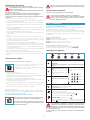
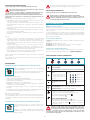
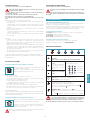
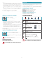
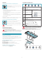
PULSANTIERA ELETTRONICA
Motore ON/OFF
Motore OFF
Impulso lungo: cambio tonalità di luce da 2700K-5600K
Incremento velocità da 1 a 4
Velocità 4 è attiva solo per al-
cuni minuti, poi si attiva velo-
cità 3.
Le velocità sono segnalate dai led
presenti nei tasti:
Velocità 1
Velocità 2
Velocità 3
Velocità 4
(led "+" lampeggiante)
Riduzione velocità da 4 a 1
Accensione / spegnimento luce
Impulso breve: accensione e spegnimento luce
Impulso lungo: regolare l'intensità
TIMER (Led rosso lampeggiante)
Autospegnimento dopo 15min.
La funzione si disattiva (Led rosso spento) se:
- Si preme un'altra volta il tasto TIMER ( ).
- Si preme il tasto ON/OFF ( ).
ALLARME FILTRI (Led rosso fisso con ( ) off)
Manutenzione filtri antigrasso dopo circa 30 ore di utilizzo.
Premere ( ) per 3 secondi per azzerare il contatore.
Se la pulsantiera è completamente inattiva, prima di contattare il
servizio di Assistenza tecnica, togliere temporaneamente (circa 5”)
l'alimentazione elettrica all'elettrodomestico, possibilmente agen-
do sull'interruttore generale, per ripristinare il normale funzionamento.
Se questo accorgimento non risultasse ecace, contattare il servizio di
Assistenza tecnica.

14
MANUTENZIONE
Prima di procedere a qualsiasi operazione di pulizia o di manu-
tenzione, disinserire l’apparecchio togliendo la spina o agendo
sull’interruttore generale.
Non si devono utilizzare detergenti contenenti sostanze abrasive, acide o
corrosive e panni con superci ruvide.
Una costante manutenzione garantisce un buon funzionamento e rendimento
nel tempo. Particolari attenzioni vanno rivolte ai filtri metallici antigrasso: la
pulizia frequente dei filtri e dei loro supporti garantisce che non si accumulino
grassi infiammabili.
PULIZIA SUPERFICI ESTERNE
Si raccomanda di pulire le superfici esterne della cappa almeno ogni 15 giorni
per evitare che le sostanze oleose o grasse possano intaccarle. Per la pulizia della
cappa, realizzata in acciaio inox spazzolato, il Costruttore consiglia l'utilizzo delle
salviette "Magic Steel" che si possono anche ordinare on-line sul sito www.e-fal-
mec.com. In alternativa e per tutti gli altri tipi di superci, la pulizia va eseguita
usando un panno umido leggermente imbevuto di detersivo neutro liquido o
con alcool denaturato.
Terminare la pulizia con un accurato risciacquo e asciugatura con panni morbidi.
Non utilizzare troppa acqua in prossimità della pulsantiera e dei
dispositivi di illuminazione per evitare che l'umidità raggiunga
parti elettroniche.
La pulizia dei pannelli in vetro va eseguita solo con detergenti specifici non cor-
rosivi o abrasivi utilizzando un panno morbido.
Il Costruttore declina ogni responsabilità qualora non vengano rispettate tali
istruzioni.
PULIZIA SUPERFICI INTERNE
E’ vietata la pulizia di parti elettriche o parti relative al motore
all’interno della cappa, con liquidi o solventi.
Per le parti metalliche interne vedi paragrafo precedente.
FILTRI METALLICI ANTIGRASSO
Si consiglia di lavare frequentemente i filtri metallici (almeno ogni mese) la-
sciandoli in ammollo per circa 1 ora in acqua bollente con detersivo per piatti,
evitando di piegarli. Non usare detergenti corrosivi, acidi o alcalini.
Risciacquarli con cura ed attendere che siano ben asciutti prima di rimontarli.
Il lavaggio in lavastoviglie è permesso, ma potrebbe creare imbrunimenti al
materiale dei filtri: per ridurre questo inconveniente utilizzare lavaggi a basse
temperature (55°C max.).
Per l’estrazione e l'inserimento dei filtri metallici antigrasso vedi figura.
FILTRI AL CARBONE E ZEOLITE (OPZIONALE KACL.961)
In condizione di normale utilizzo si consiglia di rigenerare il filtro carbone-zeolite
ogni 18 mesi e di sostituirlo dopo 3 anni. Per rigenerarlo è sufficiente inserirlo in
un normale forno domestico ad una temperatura di 200°C per circa 1 ora.
Attendere che il filtro si sia raffreddato prima di rimontarlo.
Struttura in metallo
ILLUMINAZIONE
La cappa è dotata di illuminazione tramite faretti led ad alta efficienza, basso
consumo e durata molto elevata in condizioni di normale utilizzo.
Nel caso si rendesse necessaria la sostituzione del faretto procedere come in
figura.
12V
3
1
2
SMALTIMENTO A FINE VITA
Il simbolo del cestino barrato riportato sull’apparecchiatura in suo pos-
sesso indica che il prodotto è un RAEE, cioè un “Rifiuto derivante dal-
le Apparecchiature Elettriche ed Elettroniche” e pertanto non deve
essere gettato nella spazzatura indierenziata (cioè insieme ai “rifiuti urbani
misti”), ma deve essere gestito separatamente così da essere sottoposto ad ap-
posite operazioni per il suo riutilizzo, oppure a uno specifico trattamento, per ri-
muovere e smaltire in modo sicuro le eventuali sostanze dannose per l’ambiente
ed estrarre le materie prime che possono essere riciclate. Lo smaltimento corret-
to di questo prodotto contribuirà a salvare preziose risorse ed evitare potenziali
effetti negativi per la salute umana e per l’ambiente, che potrebbero essere cau-
sati da uno smaltimento inappropriato dei rifiuti.
Vi preghiamo di contattare le autorità locali per ulteriori dettagli sul punto di
smaltimento designato più vicino. Potrebbero venire applicate delle penali per
lo smaltimento scorretto di questi rifiuti in conformità alla legislazione nazionale.
INFORMAZIONI SULLO SMALTIMENTO IN ITALIA
In Italia le apparecchiature RAEE devono perciò essere consegnate:
- ai Centri di Raccolta (chiamati anche isole ecologiche o piattaforme ecologi-
che) allestiti dai Comuni o dalle Società di igiene urbana (in molte località vie-
ne anche effettuato il servizio di ritiro a domicilio delle apparecchiature RAEE
ingombranti);
- al negozio presso il quale si acquista una nuova apparecchiatura, che è tenuto
a ritirarle gratuitamente (ritiro “uno contro uno”);
- ad un negozio qualunque*, che è tenuto a ritirarle gratuitamente e senza
obbligo di acquisto (ritiro “uno contro zero”).
In questo caso:
1) l’apparecchiatura RAEE, per poter essere riconsegnata, deve avere “piccolis-
sime dimensioni” (altezza, profondità e larghezza minori di 25 cm);
* 2) il negozio al quale viene riconsegnata l’apparecchiatura RAEE deve avere
una superficie di vendita superiore a 400 mq.
INFORMAZIONI SULLO SMALTIMENTO IN NAZIONI
DELL'UNIONE EUROPEA
La Direttiva comunitaria sulle apparecchiature RAEE è stata recepita in modo
diverso da ciascuna nazione, pertanto se si desidera smaltire questa apparec-
chiatura suggeriamo di contattare le autorità locali o il Rivenditore per chiedere
il metodo corretto di smaltimento.
INFORMAZIONI SULLO SMALTIMENTO IN NAZIONI NON APPARTENENTI
ALL'UNIONE EUROPEA
Il simbolo del cestino barrato è valido solamente nell’Unione Europea: se si de-
sidera smaltire questa apparecchiatura in altri Paesi suggeriamo di contattare le
autorità locali o il Rivenditore per chiedere il metodo corretto di smaltimento.
ATTENZIONE!
Il Costruttore si riserva il diritto di apportare modifiche alle apparecchiature in
qualsiasi momento e senza preavviso. La stampa, la traduzione e la riproduzione
anche parziale del presente manuale s’intendono vincolate dall’autorizzazione
del Costruttore.
Le informazioni tecniche, le rappresentazioni grafiche e le specifiche presenti in
questo manuale sono indicative e non divulgabili.
La lingua di stesura del manuale è l’italiano, il Costruttore non si rende responsa-
bile per eventuali errori di trascrizione o traduzione.

15
ENGLISH
SAFETY INSTRUCTIONS
AND WARNINGS
Installation operations are to be carried
out by skilled and qualied installers in ac-
cordance with the instructions in this book-
let and in compliance with the regulations in
force.
DO NOT use the hood if the power supply cable
or other components are damaged: disconnect
the hood from the electrical power supply and con-
tact the Dealer or an authorised Servicing Dealer for
repairs.
Do not modify the electrical, mechanical or func-
tional structure of the equipment.
Do not personally try to carry out repairs or re-
placements. Interventions carried out by incom-
petent and unauthorised persons can cause seri-
ous damage to the unit or physical and personal
harm, not covered by the Manufacturer's warranty.
WARNINGS FOR THE INSTALLER
TECHNICAL SAFETY
Before installing the hood, check the in-
tegrity and function of each part. Should
anomalies be noted, do not proceed with
installation and contact the Dealer.
Do NOT install the hood if an aesthetic (or cos-
metic) defect has been detected. Put it back into
its original package and contact the dealer.
No claim can be made for aesthetic (or cosmetic)
defects once it has been installed.
During installation, always use personal protective
equipment (e.g.: Safety shoes) and adopt prudent
and proper conduct.
The installation kit (screws and plugs) supplied with
the hood is only to be used on masonry walls: in case
of installation on walls of a different material, assess
other installation options keeping in mind the type
of wall surface and the weight of the hood (indicated
on page 2).
Keep in mind that installations with different types of
fastening systems from those supplied, or which are
not compliant, can cause electrical and mechanical
seal danger.
Do not install the hood outdoors and do not expose
it to atmospheric elements (rain, wind, etc.).
ELECTRICAL SAFETY
The electrical system to which the hood is
to be connected must be in accordance
with local standards and supplied with
earthed connection in compliance with safety
regulations in the country of use. It must also
comply with European standards regarding radio
antistatic properties.
Before installing the hood, check that the electrical
mains power supply corresponds with what is report-
ed on the identification plate located inside the hood.
The socket used to connect the installed equipment
to the electrical power supply must be within reach:
otherwise, install a mains switch to disconnect the
hood when required.
Any changes to the electrical system must be carried
out by a qualified electrician.
The maximum length of the flue fastening screws
(supplied by the manufacturer) must be 13 mm. Use
of non-compliant screws with these instructions can
lead to danger of an electrical nature.
Do not try to solve the problem yourself in the event
of equipment malfunction, but contact the Dealer or
an authorised Servicing Department for repairs.
When installing the hood, disconnect
the equipment by removing the plug or
switching o the main switch.
FUMES DISCHARGE SAFETY
Do no connect the equipment to discharge
pipes of fumes produced from combustion
(for example boilers, replaces, etc.).
Before installing the hood, ensure that all standards in
force regarding discharge of air out of the room have
been complied with.
Deviation for Australia and New Zeland: Range hoods
and other cooking fume extractors may adversely
affect the safe operation of appliances burning gas
or other fuels (including those in other rooms) due
to back flow of combustion gases. These gases can
potentially result in carbon monoxide poisoning.
After installation of a range hood or other cooking
fume extractor, the operation of flued gas appliances
should be tested by a competent person to ensure
that back flow of combustion gases does not occur.
(AS/NZS 60335.2.31:2013/A4:2020)
USER WARNINGS
These warnings have been drawn up for
your personal safety and those of others.
You are therefore kindly asked to read the
booklet carefully in its entirety before using the
or cleaning the equipment.
The Manufacturer declines all responsibility for
any damage caused directly, or indirectly, to per-
sons, things and pets as a consequence of failing
to comply with the safety warnings indicated in
this booklet.
It is imperative that this instructions booklet is
kept together with the equipment for any future
consultation.

16
If the equipment is sold or transferred to another per-
son, make sure that the booklet is also supplied so
that the new user can be made aware of the hood's
operation and relative warnings.
After the stainless steel hood has been installed, it
will need to be cleaned to remove any residues re-
maining from the protection adhesive as well as any
grease and oil stains which, if not removed, can cause
irreversible damage to the hood surface. To properly
clean the unit, the manufacturer recommends using
the supplied moist wipes, which are also available
sold separately. Insist on original spare parts.
INTENDED USE
The equipment is solely intended to be used to
extract fumes generated from cooking food in
non-professional domestic kitchens: any other
use is improper. Improper use can cause damage
to persons, things, pets and exempts the Manu-
facturer from any liability.
The equipment can be used by children over the age
of 8 and by persons with reduced physical, sensory and
mental abilities, or with no experience or knowledge,
as long as they do so under supervision or after having
received relative instructions regarding safe use of the
equipment and understanding of the dangers con-
nected to it. Children are not to play with the equip-
ment. Cleaning and maintenance by the user must not
be carried out by children without supervision.
USE AND CLEANING WARNINGS
Before cleaning or carrying out mainte-
nance operations, disconnect the equip-
ment by removing the plug or switching
o the main switch.
Do not use the hood with wet hands or bare feet.
Always check that all electrical parts (lights, extractor
fan) are off when the equipment is not being used.
The maximum overall weight of any objects placed
or hung (if applicable) on the hood must not exceed
1.5 Kg. Always supervise the cooking process during
the use of deep-fryers: Overheated oil can catch fire.
Do not leave open, unattended flames under the
hood. Do not prepare food over an open flame under
the hood. Never use the hood without the metal an-
ti-grease filters: in this case, grease and dirt will depos-
it in the equipment and compromise its operation.
Accessible parts of the hood can be hot when used
at the same time as the cooking appliances. Do not
carry out any cleaning operations when parts of the
hood are still hot. There can be a risk of fire if cleaning
is not carried out according to the instructions and
products indicated in this booklet. Disconnect the
main switch when the equipment is not used for long
periods of time.
If other appliances that use gas or other fu-
els are being used at the same time (boiler,
stove, replaces, etc.), make sure the room
where the fumes are discharged is well-ventilat-
ed, in compliance with the local regulations.
INSTALLATION
only intended for qualied personnel
Before installing the hood, carefully read the chapter 'SAFETY
INSTRUCTIONS AND WARNINGS'.
TECHNICAL FEATURES
The technical specifications are exhibited on the labels located inside the hood.
POSITIONING
The minimum distance between the highest part of the cooking equip-
ment and the lowest part of the hood is indicated in the installation in-
structions.
Generally, when the hood is placed over gas cookers, the distance must be at
least 65 cm (25.6''). However, according to of standard EN60335-2-31, the mini-
mum distance between the cooker and lower part of the hood can be reduced
to the quota reported in the installation instructions.
Should the instructions for the gas cooker specify a greater distance, this must
be taken into consideration.
Do not install the hood outdoors and do not expose it to outdoor environment
(rain, wind, etc.).
ELECTRICAL CONNECTION
(only intended for qualied personnel)
Disconnect the equipment from electrical mains power supply be-
fore carrying out any operations on the hood.
Ensure that the wires inside the hood are not disconnected or cut:
in the event of damage, contact your nearest Servicing Department.
Refer to qualied personnel for electrical connections.
Connection must be carried out in compliance with the provisions of law
in force.
Before connecting the hood to the electrical mains power supply, check that:
• voltage supply corresponds with what is reported on the data plate located
inside the hood;
• the electrical system is compliant and can withstand the load (see the techni-
cal specifications located inside the hood);
• the power supply plug and cable do not come into contact with tempera-
tures exceeding 70 °C;
• the power supply system is effectively and properly connected to earth in
compliance with regulations in force;
• the socket used to connect the hood is within reach.
In case of:
• devices fitted with cables without a plug: the type of plug to use is a ''stand-
ardised'' one. The wires must be connected as follows: yellow-green for earth-
ing, blue for neutral and brown for the phase. The plug must be connected to
an adequate safety socket.
• fixed equipment not provided with a power supply cable and plug, or any
other device that ensures disconnection from the electrical mains, with an
opening gap of the contacts that enables total disconnection in overvoltage
category III conditions.
Said disconnection devices must be provided in the mains power supply in
compliance with installation regulations.
The yellow/green earth cable must not be cut off by the switch.
The Manufacturer declines all responsibility for failure to comply with the safety
regulations.

17
ENGLISH
FUMES DISCHARGE
EXTERNAL EXHAUST HOOD SUCTION
In this version the fumes and vapours are discharged outside
through the exhaust pipe.
To this end, the hood outlet fitting must be connected via a
pipe, to an external output.
The outlet pipe must have:
• a diameter not less than that of the hood fitting.
• a slight slope downwards (drop) in the horizontal sections to prevent conden-
sation from flowing back into the motor.
• the minimum required number of bends.
• the minimum required length to avoid vibrations and reduce the suction per-
formance of the hood.
You are required to insulate the pipes if it passes through cold environments.
In the presence of motors with 800m3/h or higher, a check valve is present to
prevent external air flowing back.
Deviation for Germany:
when the kitchen hood is used at the same time as appliances that are powered by
energy other than electricity, the negative pressure in the room must not exceed 4 Pa
(4 x 10⁻⁵ bar).
HOOD WITH INTERNAL RECIRCULATION FILTERING
In this model, the air passes through the charcoal filters to be
purified and recycled in the environment.
Ensure that the active carbon filters are assembled into the
hood, if not, install them as indicated in the assembly instruc-
tions.
In this version the check valve must not be assembled: remove it if it is
on the air outlet fitting of the motor.
ASSEMBLY INSTRUCTIONS
only intended for personnel qualied
The hood can be installed in various congurations.
The generic assembly steps apply to all installations; for each case,
follow the specic steps provided for the required installation.
OPERATION
WHEN TO TURN ON THE HOOD?
Switch on the hood at least one minute before starting to cook to direct fumes
and vapours towards the suction surface.
After cooking, leave the hood operating until complete extraction of all vapours
and odours. By means of the Timer function, it is possible to set auto switch-off
function which will allow the hood to turn off automatically after 15 minutes of
operation.
WHICH SPEED IS TO BE SELECTED?
1st speed: maintains the circulation of clean air with low electricity consumption.
2nd speed: normal conditions of use.
3rd speed: presence of strong odours and vapours.
4th speed: rapid disposal of odours and vapours.
WHEN SHOULD THE FILTERS BE WASHED OR REPLACED?
The metal filters must be cleaned every 30 hours of operation.
For further details see the “MAINTENANCE” chap.
ELECTRONIC PUSHBUTTON PANEL
Motor ON/OFF
Motor OFF
Long impulse: change light tone from 2700K to 5600K
Increase speed from 1 to 4
Speed 4 is only active for a few
minutes, then speed 3 activates.
The speeds are indicated by the
LEDs on the keys:
Speed 1
Speed 2
Speed 3
Speed 4
("+" LED flashing)
Reduce speed from 4 to 1
Light on/o
Short impulse: turn light on and off
Long impulse: adjust intensity
TIMER (red LED flashing)
Auto switch-off after 15 min.
The function deactivates (red LED off) if:
- The TIMER key ( ) is pressed again.
- The ON/OFF key ( ) is pressed.
FILTER ALARM (red LED steady on with ( ) off)
Anti-grease filter maintenance after approximately 30 hours of oper-
ation. Press ( ) the meter for 3 seconds to reset.
If the pushbutton panel is completely inactive, before contacting
the Technical assistance service, disconnect power temporarily
to the appliance (about 5“), possibly by acting on the main
switch, to restore normal operation.
If this measure has no eect, contact the Technical assistance service.

18
MAINTENANCE
Before cleaning or carrying out maintenance operations, discon-
nect the equipment by removing the plug or switching o the
main switch.
Do not use detergents containing abrasive, acidic or corrosive substances
or abrasive cloths.
Regular maintenance guarantees proper operation and performance over time.
Special attention is to be paid to the metal anti-grease lters : frequent clean-
ing of the filters and their supports ensures that no flammable grease is accu-
mulated.
CLEANING OF EXTERNAL SURFACES
You are advised to clean the external surfaces of the hood at least once every
15 days to prevent oily substances and grease from sticking to them. To clean
the brushed stainless steel hood, the Manufacturer recommends using "Magic
Steel" wipes.
Alternatively and for all the other types of surfaces, it can be cleaned using a
damp cloth, slightly moistened with mild, liquid detergent or denatured alcohol.
Complete cleaning by rinsing well and drying with soft cloths.
Do not use too much moisture or water around the push button
control panel and lighting devices in order to prevent humidity
from reaching electronic parts.
The glass panels can only be cleaned with specific, non-corrosive or non-abra-
sive detergents using a soft cloth.
The Manufacturer declines all responsibility for failure to comply with these in-
structions.
CLEANING OF INTERNAL SURFACES
Do not clean electrical parts, or parts related to the motor inside
the hood, with liquids or solvents.
For the internal metal parts, see the previous paragraph.
METAL ANTI-GREASE FILTERS
It is advised to frequently wash the metal filters (at least once a month) leav-
ing them to soak in boiling water and cleaning solution for 1 hour, taking care
not to bend them. Do not use corrosive, acid or alkaline detergents.
Rinse them well and wait for them to be completely dry before reassembling
them. Washing in a dishwasher is permitted, however, it may cause the filter ma-
terial to darken: to reduce the possibility of this problem from happening, use
low-temperature washes (55°C max.).
To extract and insert the metal anti-grease filters see the figure.
CARBON AND ZEOLITE FILTERS (OPTIONAL KACL.961)
In normal use conditions, we recommend regenerating the zeolite-carbon filter
every 18 months and replacing it after 3 years. Simply place it in a domestic oven
at a temperature of 200°C for approximately 1 hour to regenerate it.
Wait until the filter cools before reassembling it.
Metal structure
LIGHTING
The range hood is equipped with high efficiency, low consumption LED spot-
lights with an extremely long life-span under normal use conditions.
Should the LED spotlight need to be replaced, proceed as shown in the figure.
12V
3
1
2
DISPOSAL AFTER END OF USEFUL LIFE
The crossed-out trash or refuse bin symbol on the appliance means
that the product is WEEE, i.e. “Waste electrical and electronic equip-
ment'', accordingly it must not be disposed of with regular unsort-
ed waste (i.e. with ''mixed household waste''), but it must be disposed of sepa-
rately so that it can undergo specific processing for its re-use, or a specific
treatment, to remove and safely dispose of any substances that may be harmful
to the environment and remove the raw materials that can be recycled. Proper
disposal of these products contributes to saving valuable resources and avoid
potential negative effects on personal health and the environment, which may
be caused by inappropriate disposal of waste.
You are kindly asked to contact your local authorities for further information
regarding the designated waste collection points nearest to you. Penalties for
improper disposal of such waste can be applied in compliance with national
regulations.
INFORMATION ON DISPOSAL IN EUROPEAN UNION COUNTRIES
The EU WEEE Directive was implemented differently in each country, accord-
ingly, if you wish to dispose of this appliance we suggest contacting your local
authorities or dealer to find out what the correct method of disposal is.
INFORMATION ON DISPOSAL IN NONEUROPEAN UNION COUNTRIES
The crossed-out trash or refuse bin symbol is only valid in the European Union: if
you wish to dispose of this appliance in other countries, we suggest contacting
your local authorities or dealer to find out what the correct method of disposal is.
WARNING!
The Manufacturer reserves the right to make changes to the equipment at any
time and without prior notice. Printing, translation and reproduction, even par-
tial, of this manual are bound by the Manufacturer's authorisation.
Technical information, graphic representations and specifications in this manual
are for information purposes and cannot be divulged.
This manual is written in Italian. The Manufacturer is not responsible for any tran-
scription or translation errors.

19
DEUTSCH
ANWEISUNGEN FÜR DIE SICHERHEIT
UND WARNHINWEISE
Die Installation muss von kompetenten und
qualizierten Installateuren unter Befolgung
der Angaben der vorliegenden Gebrauchsan-
weisung sowie unter Einhaltung der gültigen Sicher-
heitsvorschriften vorgenommen werden.
Wenn das Versorgungskabel oder andere Komponen-
ten beschädigt sind, darf die Abzugshaube NICHT
verwendet werden:
Die Abzugshaube von der Strom-
versorgung trennen und den Händler oder den auto-
risierten Kundendienst für die Reparatur kontaktieren.
Die elektrische, mechanische und funktionelle Struktur
des Geräts darf nicht verändert werden.
Niemals versuchen, Reparaturen oder Austauschtätig-
keiten selbst durchzuführen. Werden diese Arbeiten von
Personen durchgeführt, die nicht dazu befähigt und qua-
liziert sind, so kann dies zu schweren Personen- und
Sachschäden führen, die von der Herstellergarantie nicht
gedeckt sind.
HINWEISE FÜR DEN INSTALLATEUR
TECHNISCHE SICHERHEIT
Vor der Installation der Abzugshaube muss sicher-
gestellt werden, dass sämtliche Komponenten
unbeschädigt und funktionstüchtig sind. Sollten
Schäden festgestellt werden, nicht mit der Installation fort-
fahren und umgehend den Händler kontaktieren.
Sollte ein ästhetischer Mangel festgestellt werden, so
darf die Abzugshaube NICHT installiert werden. Die
Abzugshaube wieder verpacken und umgehend den
Händler kontaktieren.
Sobald die Abzugshaube installiert ist, werden keine
Beanstandungen aufgrund ästhetischer Mängel mehr
akzeptiert.
Während der Installation ist immer eine geeignete
persönliche Schutzausrüstung zu tragen (z.B. Sicher-
heitsschuhwerk) und aufmerksam und korrekt vorzu-
gehen.
Das mit der Abzugshaube gelieferte Befestigungs-
set (Schrauben und Dübel) darf ausschließlich für
gemauerte Wände verwendet werden. Sollte es not-
wendig sein, die Abzugshaube an einer Wand aus
anderem Material zu installieren, müssen alternative
Befestigungssysteme in Betracht gezogen werden,
wobei die Festigkeit der Wand und das Gewicht der
Abzugshaube (siehe S. 2) zu berücksichtigen sind.
Dabei ist zu beachten, dass die Installation mit Befes-
tigungssystemen, die von den mitgelieferten abwei-
chen, elektrische Gefahren und Risiken in Bezug auf
die mechanische Abdichtung mit sich bringen kann.
Die Abzugshaube darf nicht in Außenbereichen in-
stalliert und keinen Witterungseinflüssen (Regen,
Wind, etc.) ausgesetzt werden.
ELEKTRISCHE SICHERHEIT
Die elektrische Anlage für den Anschluss der
Abzugshaube muss den geltenden Normen
entsprechen und mit einem Erdungssystem
ausgestattet sein, das den Sicherheitsvorschriften des
Installationslandes entspricht. Sie muss außerdem der
EU-Gesetzgebung bezüglich der Funkentstörung ent-
sprechen.
Vor der Installation der Abzugshaube muss überprüft
werden, dass die Netzspannung derjenigen auf dem
Typenschild im Inneren der Abzugshaube entspricht.
Die für den elektrischen Anschluss verwendete Steck-
dose muss gut erreichbar sein, wenn das Gerät ins-
talliert ist. Andernfalls muss ein Hauptschalter vorge-
sehen werden, um die Abzugshaube bei Bedarf zu
trennen. Sämtliche eventuellen Änderungen an der
Elektroanlage müssen von einem qualifizierten Elek-
triker vorgenommen werden. Die Mindestlänge der
Befestigungsschraube des Kamins (vom Hersteller
mitgeliefert) beträgt 13 mm. Die Verwendung von
Schrauben, die der vorliegenden Gebrauchsanwei-
sung nicht entsprechen, kann elektrische Gefahren
mit sich bringen. Im Fall einer Störung des Geräts
nicht versuchen, das Problem eigenständig zu lösen,
sondern den Händler oder den autorisierten Kunden-
dienst für die Reparatur kontaktieren.
Während der Installation der Abzugshaube
muss das Gerät durch Ziehen des Netzsteckers
oder Betätigung des Hauptschalters abgeschaltet wer-
den.
SICHERHEIT RAUCHABZUG
Das Gerät nicht an Rohre für den Abzug von
Rauch anschließen, der durch Verbrennung ent-
steht (z.B. Heizkessel, Kamine, etc.).
Vor der Installation der Abzugshaube muss sicherge-
stellt werden, dass alle gültigen gesetzlichen Vorschri-
ften in Bezug auf die Luftableitung aus dem Raum
eingehalten werden.
Abweichende Bestimmungen für Australien und
Neuseeland: Dunstabzugshauben und andere Ab-
zugshauben für Kochdämpfe könnten den sicheren
Betrieb von Geräten, die Gas oder andere Brenn-
stoffe verbrennen (einschließlich solcher in anderen
Räumen), aufgrund eines Rückflusses von Verbren-
nungsgasen beeinträchtigen. Diese Gase können
möglicherweise zu einer Kohlenmonoxidvergiftung
führen. Nach der Installation einer Dunstabzugshau-
be oder anderen Abzugshauben für Kochdämpfe
sollte die Funktion der Gasfeuergeräte von einer kom-
petenten Person geprüft werden, um sicherzustellen,
dass kein Rückfluss von Verbrennungsgasen auftritt.
(AS/NZS 60335.2.31:2013/A4:2020)

20
HINWEISE FÜR DEN BENUTZER
Diese Hinweise wurden für Ihre Sicherheit und
die Sicherheit anderer Personen erstellt, und
wir bitten Sie deshalb, die vorliegende Ge-
brauchsanweisung vor der Installation, der Verwen-
dung oder der Reinigung des Geräts vollständig zu le-
sen. Der Hersteller lehnt jegliche Haftung für etwaige
direkte oder indirekte Schäden von Personen, Gegen-
ständen oder Haustieren ab, die durch eine Nichtbe-
achtung der in der vorliegenden Gebrauchsanweisung
angeführten Sicherheitshinweise verursacht werden.
Es ist sehr wichtig, dass diese Gebrauchsanweisung zu-
sammen mit dem Gerät aufbewahrt wird, damit künf-
tig darin nachgelesen werden kann.
Falls das Gerät verkauft oder an eine andere Person
übergeben wird, muss sichergestellt werden, dass
auch die Gebrauchsanweisung übergeben wird, da-
mit der neue Besitzer informiert werden kann, wie die
Abzugshaube funktioniert und welche diesbezügli-
chen Warnhinweise zu beachten sind.
Nach der Installation der Edelstahlhaube muss als Ers-
tes deren Reinigung erfolgen, um die Rückstände der
Schutzklebefolie und eventuelle Flecken von Öl oder
Fett zu entfernen, die die Oberfläche der Abzugshau-
be unwiderruflich beschädigen können, falls sie nicht
entfernt werden. Für diesen Vorgang empfiehlt der
Hersteller, die mitgelieferten Reinigungstücher zu be-
nutzen, die auch gekauft werden können.
Immer die Verwendung von originalen Ersatzteilen
fordern.
VERWENDUNGSBESTIMMUNG
Das Gerät ist ausschließlich für die Absaugung von
Rauch bestimmt, der während der Zubereitung von
Speisen in Haushaltsküchen, nicht in gewerblichen
Küchen, erzeugt wird. Jede andere Verwendung gilt
als unsachgemäß, kann Schäden an Personen, Gegen-
ständen und Haustieren verursachen und enthebt den
Hersteller von jeglicher Verantwortung.
Dieses Gerät kann von Kindern ab 8 Jahren sowie von
Personen mit reduzierten physischen, sensorischen
oder mentalen Fähigkeiten oder Mangel an Erfah-
rung und/oder Wissen benutzt werden, wenn sie
beaufsichtigt oder bezüglich des sicheren Gebrauchs
des Gerätes unterwiesen wurden und die damit zu-
sammenhängenden Gefahren verstanden haben.
Kinder dürfen nicht mit dem Gerät spielen. Kinder
dürfen die vom Benutzer auszuführende Reinigung
und Wartung nicht unbeaufsichtigt durchführen.
HINWEISE FÜR VERWENDUNG UND REINIGUNG
Die Abzugshaube nicht mit nassen Händen
oder nackten Füßen verwenden.
Immer kontrollieren, dass alle elektrischen
Teile (Beleuchtung, Absauganlage) ausgeschaltet
sind, wenn das Gerät nicht verwendet wird.
Das maximale Gesamtgewicht eventuell auf der
Abzugshaube abgestellter oder an ihr aufge-
hängter Gegenstände (falls vorgesehen) darf 1,5
kg nicht überschreiten.
Fritteusen müssen während des Betriebs über-
wacht werden: Das erhitzte Öl könnte Feuer fan-
gen. Unter der Haube keine oenen Flammen
verwenden. Unterhalb der Abzugshaube keine
Garvorgänge mit "oenen" Flammen ausführen.
Die Abzugshaube nie ohne Metallfettlter ver-
wenden. In diesem Fall würden sich Fett und
Schmutz auf dem Gerät absetzen und seine Funk-
tionstüchtigkeit beeinträchtigen.
Die erreichbaren Teile der Abzugshaube können
heiß sein, wenn sie zusammen mit Kochgeräten
verwendet werden.
Mit der Reinigung so lange warten, bis alle Teile
der Abzugshaube abgekühlt sind.
Sollte die Reinigung nicht gemäß den Vorschrif-
ten und mit den Produkten ausgeführt werden,
die im vorliegenden Handbuch angegeben sind,
so besteht Brandgefahr.
Wenn das Gerät über einen längeren Zeitraum
nicht verwendet wird, muss der Hauptschalter
abgeschaltet werden.
Bei gleichzeitiger Verwendung anderer mit Gas
oder anderen Brennstoen gespeister Verbrau-
cher (Heizkessel, Öfen, Kamine, etc.) für eine an-
gemessene, vorschriftsmäßige Lüftung des Raumes
sorgen, in dem die Dunstabsaugung erfolgt.
INSTALLATION
Dieser Abschnitt ist ausschließlich qualiziertem Personal vorbehalten
Vor der Installation der Abzugshaube muss das Kapitel "ANWEISUNGEN
FÜR DIE SICHERHEIT UND WARNHINWEISE" aufmerksam gelesen wer-
den.
TECHNISCHE MERKMALE
Die technischen Daten des Geräts sind auf den Schildern im Inneren der Abzugs-
haube angegeben.
La pagina sta caricando ...
La pagina sta caricando ...
La pagina sta caricando ...
La pagina sta caricando ...
La pagina sta caricando ...
La pagina sta caricando ...
La pagina sta caricando ...
La pagina sta caricando ...
La pagina sta caricando ...
La pagina sta caricando ...
La pagina sta caricando ...
La pagina sta caricando ...
La pagina sta caricando ...
La pagina sta caricando ...
La pagina sta caricando ...
La pagina sta caricando ...
La pagina sta caricando ...
La pagina sta caricando ...
La pagina sta caricando ...
La pagina sta caricando ...
La pagina sta caricando ...
La pagina sta caricando ...
La pagina sta caricando ...
La pagina sta caricando ...
La pagina sta caricando ...
La pagina sta caricando ...
La pagina sta caricando ...
La pagina sta caricando ...
La pagina sta caricando ...
La pagina sta caricando ...
La pagina sta caricando ...
La pagina sta caricando ...
La pagina sta caricando ...
La pagina sta caricando ...
La pagina sta caricando ...
La pagina sta caricando ...
La pagina sta caricando ...
La pagina sta caricando ...
La pagina sta caricando ...
La pagina sta caricando ...
La pagina sta caricando ...
La pagina sta caricando ...
La pagina sta caricando ...
La pagina sta caricando ...
La pagina sta caricando ...
La pagina sta caricando ...
La pagina sta caricando ...
La pagina sta caricando ...
La pagina sta caricando ...
La pagina sta caricando ...
La pagina sta caricando ...
La pagina sta caricando ...
-
 1
1
-
 2
2
-
 3
3
-
 4
4
-
 5
5
-
 6
6
-
 7
7
-
 8
8
-
 9
9
-
 10
10
-
 11
11
-
 12
12
-
 13
13
-
 14
14
-
 15
15
-
 16
16
-
 17
17
-
 18
18
-
 19
19
-
 20
20
-
 21
21
-
 22
22
-
 23
23
-
 24
24
-
 25
25
-
 26
26
-
 27
27
-
 28
28
-
 29
29
-
 30
30
-
 31
31
-
 32
32
-
 33
33
-
 34
34
-
 35
35
-
 36
36
-
 37
37
-
 38
38
-
 39
39
-
 40
40
-
 41
41
-
 42
42
-
 43
43
-
 44
44
-
 45
45
-
 46
46
-
 47
47
-
 48
48
-
 49
49
-
 50
50
-
 51
51
-
 52
52
-
 53
53
-
 54
54
-
 55
55
-
 56
56
-
 57
57
-
 58
58
-
 59
59
-
 60
60
-
 61
61
-
 62
62
-
 63
63
-
 64
64
-
 65
65
-
 66
66
-
 67
67
-
 68
68
-
 69
69
-
 70
70
-
 71
71
-
 72
72


Falmec Move Manuale utente
- Categoria
- Cappe da cucina
- Tipo
- Manuale utente
- Questo manuale è adatto anche per
in altre lingue
- English: Falmec Move User manual
- français: Falmec Move Manuel utilisateur
- español: Falmec Move Manual de usuario
- Deutsch: Falmec Move Benutzerhandbuch
- Nederlands: Falmec Move Handleiding
- português: Falmec Move Manual do usuário
- dansk: Falmec Move Brugermanual
- svenska: Falmec Move Användarmanual
Documenti correlati
-
Falmec FDMOV24W5SB Range Hood Manuale utente
-
Falmec F3MV12W1 Manuale del proprietario
-
Falmec MOVE 90 BLACK Manuale del proprietario
-
-
-
-
-
-
-