
Bart 350 -
GB Instructions manual
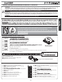
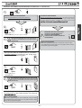
EN 13241
EN 12453
EN 12445

- 2 -
CARATTERISTICHE DEL BART 350
Il BART 350 è un apricancello elettromeccanico con braccio articolato o diritto su guida in acciaio zincato, progettato per essere installato nelle aperture a
con la sicurezza di una serratura a chiave personalizzata. Nelle installazioni di minor ingombro si puo’ installare il braccio diritto su guida scorrevole: necessita
possono eseguire grazie alla comoda maniglia di sblocco, resa sicura in posizione da una serratura con chiave cifrata personalizzata. Nelle installazioni a doppia
anta Master-Slave il solo programmatore Elpro 35M a bordo del Bart 350 Master gestisce l’intero impianto e la programmazione di entrambi i motori.
del Bart 350 Master ed eseguire tutti i collegamenti degli accessori sull’Elpro 35M.
Sul Bart 350 Slave è presente una schedina di collegamento Elpro 35S. Il Bart 350 è munito di sensore amperometrico per l’arresto in battuta dell’anta e l’inversione di
marcia all’urto con ostacoli.
BART 350 CHARACTERISTICS
BART 350 is an electro-mechanical gate opener with an articulated or straight arm on a galvanised steel guide, designed for installation on swinging opening
residential or condominium doors or gates, for intensive use, to be secured directly on pillars. The entire geared motor unit is installed on an anchor plate.
motor is to be mounted as next step. Limit switches are pre-installed under the Anchor plate. A cover closes the entire system with the safety of a customised
key lock. On smaller sized installations, a straight arm with a sliding guide can be installed. This requires the use of the limit switches or ground stops (opening
and closing). In the absence of mains power, opening and closing movements can be carried out thanks to the convenient unlock handle, secured in position
by a lock with a customised coded key. In dual Master-Slave installations, the single Elpro 35M programmer on board the Bart 350 Master manages the entire
system and programming of both motors.
Master pillar and carry out all Elpro 35M accessory connections.
An Elpro 35S connection board is present on the Bart 350 Slave. The Bart 350 is equipped with an amperometric sensor for stopping the gate on end stop and reversing
upon impact with obstacles.
CARACTERISTIQUES DU BART 350
Le BART 350 est un ouvre-portail électromécanique avec bras articulé ou droit sur rail en acier zingué, conçu pour être installé dans les ouvertures à battant de
referme le tout avec la sécurité d’une serrure à clé personnalisée. Dans les installations moins encombrantes, il est possible d’installer le bras droit sur rail de
les installations à double vantail Master-Slave, l’unique programmateur Elpro 35M intégré dans le Bart 350 Master gère l’ensemble de l’installation et la programmation
de deux moteurs.
Le Bart 350 Slave dispose d’une carte de connexion Elpro 35S. Le Bart 350 est
équipé d’un capteur ampérométrique prévu pour l’arrêt en butée du vantail et l’inversion de marche en cas de choc sur obstacles.
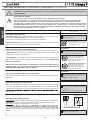
! VERIFICHE PRELIMINARI PRIMA DELL’INSTALLAZIONE ! elled azzerucis id inoizacidni el ettut odneuges ,enoizallatsni id aloger anoub al odnoces ocincet elanosrep ad atauttee eresse eved enoizallatsni’L
normative EN 12445 e EN 12453: si consiglia di prendere visione delle Normative di Sicurezza che la Meccanica Fadini mette a disposizione degli installatori
(www.fadini.net/ supporto/downloads).
- Verificare l’idoneita’ dei cardini e delle cerniere di movimento dell’anta, togliendo tutti gli attriti ed eventuali impuntamenti durante tutto il movimento
dell’anta, installando sistemi anticaduta come prescrivono le normative di sicurezza nelle installazioni di porte e cancelli (fig.3)
- L’anta e la struttura portante del cancello devono essere ben strutturati e devono avere una suciente rigidità ad essere automatizzati (fig.3)
- Verificare che il gioco sulle cerniere sia contenuto e che l’anta non esca dai vincoli.
- L’attacco del braccio articolato sull’anta ( fig.6) deve essere fissato in corrispondenza di un rinforzo o su di un traverso strutturale (fig.3)
L’intera struttura del cancello deve rispettare le norme di sicurezza di fabbricazione ed installazione che esulano dalla competenza della ditta Meccanica
Fadini quale costruttrice dell’apricancello e dei suoi accessori di funzionamento.
! PRELIMINARY CHECKS BEFORE INSTALLATION !
Installation must be carried out by technical personnel in accordance with proper installation rules, following all safety instructions contained in norms
EN 12445 and EN 12453. It is furthermore recommended that the Safety Regulations made available to installers by Meccanica Fadini be examined
thoroughly (www.fadini.net/ supporto/downloads).
- Verify the suitability of the gate pivots and hinges, removing all friction and any jamming during gate movement, installing fall protection systems as
required by door and gate installation safety norms (fig.3).
- The gate must be properly structured and must be properly rigid to take an automatic system (fig.3).
- Verify that clearance on the hinges is not excessive and the gate is not in danger of falling down.
- Articulated arm attachment on the gate ( fig.6) must be secured in correspondence of a reinforcement or on a structural beam (fig.3).
The entire gate structure must comply with the gate manufacturer and installation safety norms, not of competence of the Meccanica Fadini company, as
manufacturer of gate automation and operational accessories.
! CONTROLES PRELIMINAIRES AVANT L’INSTALLATION !
L’installation doit être eectuée par personnel qualifié conformément aux instructions, en respectant toutes les consignes de sécurité des normes EN 12445
et EN 12453 : nous conseillons de consulter les Règlementations de Sécurité mises à la disposition des installateurs par Meccanica Fadini (www. fadini.net/
supporto/dowloads).
- Vérifier la conformité des gonds et des charnières de mouvement du vantail, en éliminant tous les frottements et les éventuels blocages durant le mouvement
.)3.gfi( sliatrop sed te setrop sed snoitallatsni sel snad étirucés ed semron sel tneiovérp e
l emmoc etuhcitna semètsys sed tnallatsni ne te ,liatnav ud telpmoc
- Le vantail et la structure porteuse du portail doivent être solidement fixés et susamment rigides pour être automatisés (fig.3).
- Vérifier que le jeu sur les charnières soit limité et que le vantail ne sorte pas des gonds.
- La fixation du bras articulé sur le vantail ( fig.6) doit être eectuée au niveau d’un renfort ou sur une structure transversale (fig.3).
L’ensemble de la structure du portail doit respecter les normes de sécurité de construction et d’installation qui sont en dehors de la compétence de
l’entreprise Meccanica Fadini, fabricant de l’ouvre-portail et de ses accessoires de fonctionnement.
IT
GB
FR

- 3 -
MERKMALE VON BART 350
BART 350
oder Wohnanlagen, intensive Nutzung, direkt an Pfeiler zu befestigen. Das gesamte Getriebemotor wird an einer Montageplatte installiert, an der zunächst der
Stoppanschlag (falls erforderlich) angebracht wird. Normalerweise wird empfohlen, zunächst Stoppanschlag am Boden zu befestigen, dann den Getriebemotor
Elektroschloss. Bei kleineren Installationen kann man den geraden Arm auf einer Gleitschiene installieren: dabei ist die Verwendung von Endschaltern oder
Anlage und die Programmierung beider Motoren.
Dann alle weiteren Anschlüsse an Bart 350 Master vorbereiten und die Zubehörgeräte an Elpro 35M anschließen.
An Bart 350 Slave wird die Verbindungsplatine Elpro 35S angeschlossen. Bart 350 ist mit einem Strommessugssensor zum Stopp am Anschlag und zum Richtungswechsel
des Flügel bei Aufprall gegen ein Hindernis ausgestattet.
CARACTERÍSTICAS DE BART 350
BART 350 es un abrepuertas electromecánico con un brazo articulado o recto sobre una guía de acero galvanizado, diseñado para ser instalado en aberturas
alimentación eléctrica de red, las maniobras de apertura y cierre se pueden realizar gracias a la cómoda manilla de desbloqueo, dispuesta segura en posición
de una cerradura con llave cifrada personalizada. En aquellas instalaciones con doble hoja Master-Slave el programador Elpro 35M a borde de Bart 350 Master gestiona
todo el sistema y la programación de ambos motores.
pilar de Bart 350 Master y realizar todas las conexiones de los accesorios sobre Elpro 35M. Sobre Bart 350 Slave se encuentra presente un tarjeta de conexión Elpro
35S. Bar 350 está compuesto por un sensor amperométrico para detener el tope de la hoja y la inversión de marcha al golpear con algún obstáculo.
EIGENSCHAPPEN VAN BART 350
BART 350 is een elektromechanische poortopener met een scharnierarm of een rechte arm op een geleider van verzinkt staal, ontworpen voor de installatie op
draaipoorten van woningen of appartementencomplexen, voor een intensief gebruik en een directe bevestiging aan de pilaar. De reductiemotorgroep wordt
geïnstalleerd op de bevestigingsplaat, waarop eerst de stopaanslagen voor het openen en sluiten (indien noodzakelijk) - in andere gevallen worden aanslagen
op de grond aanbevolen - en vervolgens de reductiemotorgroep worden bevestigd. De eindaanslagen zijn al onder de bevestigingsplaat aangebracht. Een kap
sluit alles af met de veiligheid van een slot met een persoonlijke sleutel. Op kleinere installaties kan de rechte arm direct op de geleider worden geïnstalleerd:
deze installatie vereist het gebruik van eindaanslagen en aanslagen aan de grond (voor het openen en sluiten). Als de elektrische voeding ontbreekt, kan
de poort worden geopend en gesloten met behulp van de handige deblokkeringshendel. De hendel wordt beveiligd dankzij een slot met een persoonlijke
gecodeerde sleutel. In installaties met dubbele draaipoort Master-Slave beheert uitsluitend de programmeereenheid Elpro 35M op de Bart 350 Master de hele
installatie en de programmering van de beide motoren. U moet bepalen waar u de Bart 350 Master installeert die de eerste draaipoort tijdens het openen aanstuurt.
Vervolgens voert u de systemen naar de paal van de Bart 350 Master en sluit u alle accessoires aan op de Elpro 35M. Bart 350 Slave bevat een kaart voor de
aansluiting op Elpro 35S. Bart 350 is voorzien van een ampèrometrische sensor die de draaipoort op de aanslag tot stilstand brengt en de beweging omkeert als
obstakels worden geraakt.
! VORABKONTROLLEN VOR DER INSTALLATION! !
Die Installation muss von Fachpersonal fachgerecht und unter Beachtung alle Sicherheitsvorgaben der Gesetzesvorschriften EN 12445 und EN 12453
ausgeführt werden: beachten Sie diesbezüglich die Sicherheitsvorschriften die Meccanica Fadini für Installateure zur Verfügung stellt (www. fadini.net/
supporto/downloads).
- Eignung von Angeln und Scharnieren des Torflügels prüfen, Reibungspunkte an der Bewegung entfernen und Fallschutzvorkehrungen treen, wie sie von
Sicherheitsvorschriften für Tür- und Toranlagen gefordert sind (Abb. 3)
- Torflügel und Tragestruktur müssen kräftig strukturiert und für einen Automatikantrieb ausreichend stabil sein (Abb. 3).
- Sicherstellen, dass der Spielraum an den Scharnieren nicht zu groß ist und der Flügel nicht aus der Aufhängung rutschen kann.
- Der Anschluss des Gelenkarms am Flügel ( Abb. 6) muss an einer Verstärkung oder einen Tragebalken befestigt werden (Abb.3).
Die gesamte Struktur muss den Sicherheitsvorschriften für Fertigung und Installation entsprechen, die außerhalb der Kompetenz der Firma Meccanica
Fadini als Hersteller des Torantriebs und seiner Zubehörteile fallen.
! VERIFICACIONES PREVIAS ANTES DE REALIZAR LA INSTALACIÓN !
La instalación debe ser realizada por personal técnico según la buena regla de instalación, siguiendo todas las indicaciones de seguridad de las normativas
EN 12445 y EN 12453: se recomienda visualizar las Normativas de Seguridad que Meccanica Fadini pone a disposición del personal encargado de realizar la
instalación (www.fadini.net/ supporto/dowloads).
- Verificar la idoneidad de los cardanes y de las cremalleras de movimiento de la hoja, retirando todas fricciones y posibles enganches durante todo el movimiento
de la hoja, instalando sistemas de anti caída tal y como prescriben las normativas de seguridad en las instalaciones de puertas y puertas de exteriores (fig.3)
- La hoja y la estructura portante de la puerta externa deben estar bien estructuradas y tener una suficiente rigidez para ser automatizadas (fig.3).
- Verificar que el juego de las cremalleras sea reducido y que la hoja no salga de las restricciones.
- El enganche del brazo articulado sobre la hoja ( fig.6) debe ser fijado en correspondencia de un refuerzo o sobre un travesaño estructural (fig.3).
Toda la estructura de la puerta externa debe respetar las normas de seguridad de fabricación y de instalación que están fuera de la competencia de la
empresa Meccanica Fadini fabricante del abrepuertas y de sus accesorios de funcionamiento.
! CONTROLES VOOR DE INSTALLATIE! !
Technisch personeel moet de installatie op correcte wijze verrichten door de veiligheidsaanwijzingen van de normen EN 12445 en En 12453 na te leven: we
raden aan dat de veiligheidsnormen die Meccanica Fadini ter beschikking stelt van de installateurs (www.fadini.net/supporto/dowloads) worden doorgelezen.
- Controleer of de (klap)scharnieren voor de beweging van de draaipoort geschikt zijn, door alle wrijving en eventuele blokkeringen in het bewegingsveld
van de draaipoort te verwijderen en vanginstallaties te installeren zoals wordt voorgeschreven door de veiligheidsnormen voor de installatie van poorten
en hekken (afb.3).
- De draaipoort en de dragende structuur moeten goed gestructureerd en stevig genoeg zijn om te kunnen worden aangedreven (afb.3)
- Controleer of de scharnieren weinig speling vertonen en of de draaipoort nooit losraakt.
- De bevestiging van de scharnierarm op de draaipoort ( afb.6) moet ter hoogte van een versterking of een structurele dwarsbalk worden aangebracht (afb.3)
De hele structuur van de draaipoort moet voldoen aan de productie en installatie veiligheidsnormen die buiten de competentie van de fabrikant van de
poortopener en de bijbehorende accessoires vallen.
DE
ES
NL

- 4 -
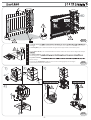
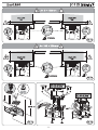
Fig. 1
Fig. 2
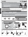
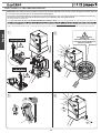
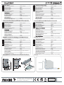
Predisporre l’alimentazione e le utenze sul Bart 350 Master, che deve essere obbligatoriamente quello collocato sulla prima
anta in apertura ed ultima in chiusura.
Set power and connections to Bart 350 Master,
Prédisposer l’alimentation et les dispositifs sur le Bart 350 Master, qui doit être obligatoirement installé sur le premier vantail
en ouverture et dernier en fermeture.
Versorgung und Anschlüsse an Bart 350 Master vorbereiten,
zuletzt schließt.
Preparar la alimentación y los usos sobre Bart 350 Master, que debe ser obligatoriamente colocado sobre la primer hoja abierta
y la última cerrada.
Sluit de voeding en de systemen aan op de Bart 350 Master, die verplicht is geplaatst op de draaipoort die als eerste beweegt
tijdens het openen en als laatste tijdens het sluiten.
cod. 351L S/N 201406 R: 2014
Max gate width:
Speed (95°): 16s IP 53 -20°C +50°C
2,3m (max. 200kg)
250kg (max. 1,5m)
cod. 352L S/N 201406 R: 2014
SLAVE
Max gate width:
Speed (95°): 16s IP 53 -20°C +50°C
2,3m (max. 200kg)
250kg (max. 1,5m)
IT
GB
FR
DE
ES
NL
IT
GB
FR
DE
ES
NL

- 5 -
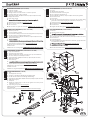
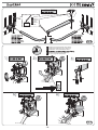
Fig. 5
Fig. 4
Fig. 3
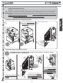
Per pilastri stretti
ancoraggio.
For narrow pillars, put a reinforcement blade along the entire support surface of the Anchor plate.
Pour des piliers étroits, il est conseillé d’installer une lame de renfort sur toute la surface d’appui de la Plaque
Bei schmalen Pfeilern
Verankerungsplatte empfohlen.
Para pilares estrechos
Placa de anclaje.
In het geval van smalle pilaren, raden we u aan om een verstevigingsstrip aan te brengen
op het steunoppervlak van de ankerplaat.
IT
GB
FR
DE
ES
NL

- 6 -
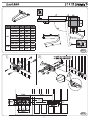
Fig. 6
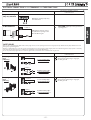
MAIN COMPONENTS (included in the KIT)
1 Casing
2 LED lamp (blue and amber)
3 Manual unlock handle and casing lock
4 N°2 Coded key for manual unlock
5 Elpro 35M (Bart 350 Master) or Elpro 35S (Bart 350 Slave) Programmer
6 Geared motor unit
7 Anchor plate
8 Cams and limit switch Microswitches necessary for the arm with sliding
guide and recommended for light gates (aluminium, wood, PVC, etc.)
9 Opening gate stop if not present on the ground
10 Articulated arm attachment on the gate
11 Articulated arm
12 Straight arm with sliding guide (used only with limit switches)
HAUPTKOMPONENTEN (im Kit enthalten)
1 Gehäuse
2 Led-Leuchte (blau und gelb)
3
4 N°2 codierten Schlüssel zur manuellen Entriegelung
5 E-Steuerung Elpro 35M (Bart 350 Master) oder Elpro 35S (Bart 350 Slave)
6 Getriebemotor
7 Verankerungsplatte
8 Nocken und Mikro der Endschalter für den Schiebearm, geeignet für leichte
Tore (Aluminium, Holz, PVC,...)
9 Bodenstopper vorhanden sind
10
11 Gelenkarm
12 Gerader Arm mit Gleitschiene (nur bei vorhandenen Endschaltern)
COMPOSANTS PRINCIPAUX (fournis avec le KIT)
1 Boîtier de protection
2 Lampe à led (bleu et ambre)
3 Levier de déverrouillage manuel et de verrouillage du boîtier de protection
4 N°2 Clés codées pour le déverrouillage manuel
5 Programmateur Elpro 35M (Bart 350 Master) ou Elpro 35S (Bart 350 Slave)
6 Groupe Motoréducteur
7
8
et indiqué pour des portails légers (aluminium, bois, pvc,...)
9 Butée d’arrêt en ouverture si elles ne sont pas installées au sol.
10 Fixation sur le vantail du bras articulé
11 Bras articulé
12 Bras droit avec rail de guidage
CONIPONENTES PRINCIPALES (suministrados en el KIT)
1 Capó de recubrimiento
2 Lámpara de led (azul y ámbar)
3 Manilla de desbloqueo manual y de bloqueo del capó de recubrimiento
4 N°2 Llave cifrada para el desbloqueo manual
5 Programador Elpro 35M (Bart 350 Master) o Elpro 35S (Bart 350 Slave)
6 Grupo Motorreductor
7 Placa de anclaje
8
e indicado para puertas externas ligeras (aluminio, madera. pvc,...)
9 Tope de detención en apertura si no están presentes en tierra
10 Enganche sobre la hoja del brazo articulado
11 Brazo articulado
12
Brazo recto con guía de desplazamiento
HOOFDCOMPONENTEN (in de KIT)
1 Kap
2 Led lamp (blauw en oranje)
3 Hendel voor handmatige deblokkering en blokkering kap
4 N°2 Gecodeerde sleutel voor handmatige deblokkering
5 Programmeereenheid Elpro 35M (Bart 350 Master) of Elpro 35S (Bart 350 Slave)
6 Reductiemotorgroep
7 Ankerplaat
8 Nokken en eindaanslagen voor de arm met geleider voor lichte poorten
(aluminium, hout, pvc,...)
9 Stopaanslag voor openen
niet aan de grond
10 Bevestiging scharnierarm aan draaipoort
11 Scharnierarm
12 Rechte arm met geleider
(uitsluitend in combinatie met eindaanslagen)
COMPONENTI PRINCIPALI (forniti nel KIT)
1 Cofano di copertura
2 Lampada a led (blu e ambra)
3 Maniglia di sblocco manuale e di blocco cofano di copertura
4 N°2 Chiavi cifrate per lo sblocco manuale
5 Programmatore Elpro 35M (Bart 350 Master) o Elpro 35S (Bart 350 Slave)
6 Gruppo Motoriduttore
7 Piastra di ancoraggio
8
scorrimento e indicato per cancelli leggeri (alluminio, legno, pvc,...)
9 Battuta di arresto in apertura se non presenti a terra
10 Attacco sull’anta del braccio articolato
11 Braccio articolato
12 Braccio diritto con guida di scorrimento
IT GB
FR
ES
NL
DE

- 7 -
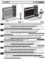
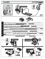
Fig. 8
Fig. 7
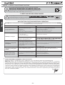
OA BCD
95°
0-50 70 400 235
50-100 70 400 235
100-130 80 400 215
130-150 80 400 200
150-180 80 420 195
180-200 90 440 180
200-220 90 440 155
110° 10-50 130 400 260
50-100 150 400 240

- 8 -
Fig. 10Fig. 9
SCELTA DEL TIPO DI BATTUTA DEL CANCELLO: L’UTILIZZO DELLE BATTUTE RIGIDE È INDICATO PER CANCELLI IN FERRO. PER CANCELLI
IN MATERIALE DEFORMABILE QUALE LEGNO, PVC, ALLUMINIO, PLEXIGLAS,... È INDICATO L’UTILIZZO DEI MICRO DI FINECORSA.
È necessario scegliere il tipo di battuta del cancello prima di inserire e fissare il motoriduttore sulla Piastra di Ancoraggio.
1) Battuta a terra: la ditta costruttrice consiglia di utilizzare sempre le battute di apertura e chiusura a terra
2) Battute sulla piastra di fissaggio: in particolari installazioni dove non e’ possibile utilizzare le battute a terra, viene predisposta la
e , sotto la Piastra di Ancoraggio.
Tale scelta deve essere fatta prima di installare il gruppo motoriduttore sulla Piastra di Ancoraggio.
CHOOSING THE TYPE OF GATE STOP: RIGID STOPS ARE RECOMMENDED FOR IRON GATES. FOR GATES IN DEFORMABLE MATERIAL,
SUCH AS WOOD, PVC, ALUMINIUM, PLEXIGLASS, ETC., THE USE OF LIMIT SWITCH MICROSWITCHES IS RECOMMENDED.
You must choose the type of gate end stop before inserting and securing the geared motor on the Anchor Plate.
1) Ground end stop: the manufacturer recommends always using opening and closing ground end stops
2) End stops on anchor plates: in special installation where ground end stops cannot be used, there is the possibility of securing opening
and closing end stop blocks, according to and , under the Anchor Plate. This choice must be made before installing the geared
motor unit on the Anchor Plate.
CHOIX DU TYPE DE BUTEE DU PORTAIL : L’UTILISATION DES BUTEES RIGIDES EST INDIQUEE POUR DES PORTAILS EN FER. POUR DES PORTAILS EN
MATERIAU DEFORMABLE TELLES QUE LE BOIS, PVC, ALUMINIUM, PLEXIGLAS, ... NOUS CONSEILLONS D’UTILISER DES MICROS DE FIN DE COURSE .
Il est nécessaire de choisir le type de butée du portail avant d’insérer et de fixer le motoréducteur sur la Plaque de Fixation.
1) Butée au sol : l’entreprise de construction conseille de toujours utiliser les butées d’ouverture et de fermeture au sol
2) Butées sur la plaque de fixation : en cas d’installations spéciales qui ne permettent pas l’utilisation des butées au sol, il est prévu de
et , sous la Plaque de Fixation.
avant d’installer le groupe motoréducteur sur la Plaque de Fixation.
AUSWAHL DES ANSCHLAGS: DIE VERWENDUNG HARTER ANSCHLÄGE IST FÜR EISENTORE GEEIGNET: FÜR TORE AUS VERFORMBAREM
MATERIAL WIE HOLZ, PVC, ALUMINIUM, PLEXIGLAS,... EIGNET SICH DER GEBRAUCH VON ENDSCHALTERN.
Der Toranschlag muss vor dem Einsetzen und Fixieren des Getriebemotors an der Verankerungsplatte gewählt werden.
1) Bodenanschlag: (Abb.9)
2) Anschläge an der Verankerungsplatte: insbesondere bei Installationen, bei denen Bodenanschläge nicht verwendet werden können,
besteht die Möglichkeit zur Anbringung von Anschlägen unter der Verankerungsplatte, siehe Abb. 11 und Abb. 12. Der Toranschlag muss vor
dem Einsetzen und Fixieren des Getriebemotors an der Verankerungsplatte gewählt werden.
SELECCIONAR EL TIPO DE TOPE DE LA PUERTA EXTERNA: EL USO DE TOPES RÍGIDOS ESTÁ INDICADO PARA PUERTAS DE HIERRO. PARA PUERTAS
REALIZADAS EN MATERIAL DEFORMABLE COMO MADERA, PVC, ALUMINIO, PLEXIGLAS, ... SE RECOMIENDA UTILIZAR MICRO DE FIN DE CARRERA.
Es necesario seleccionar el tipo de tope de la puerta antes de introducir y fijar el motorreductor sobre la Placa de Anclaje.
1) Tope de tierra: la empresa fabricante recomienda utilizar siempre topes de apertura y cierre de tierra
2) Topes sobre la placa de fijación: en instalaciones particulares en donde no es posible utilizar topes de tierra, se predispone la
y , debajo de la Placa de Anclaje.
Esta selección debe ser realizada antes de instalar el grupo del motorreductor sobre la Placa de Anclaje.
DE AANSLAG VAN DE POORT BEPALEN: VOOR IJZEREN POORTEN WORDEN STUGGE AANSLAGEN AANBEVOLEN. VOOR POORTEN VAN
VERVORMBAAR MATERIAAL, ZOALS HOUT, PVC, ALUMINIUM, PLEXIGLAS,... WORDT HET GEBRUIK VAN EINDAANSLAGEN AANBEVOLEN.
Kies het type aanslag van de poort voor u de reductiemotor op de ankerplaat aanbrengt en vastzet.
1) Aanslag aan de grond:
2) Aanslagen op ankerplaat: in bijzondere installaties waarin de aanslagen aan de grond niet kunnen worden gebruikt, kunnen
aanslagblokken voor het openen en sluiten worden aangebracht onder de ankerplaat, zie de schema’s van en . Maak deze keuze
voor u de reductiemotorgroep op de ankerplaat installeert.
IT
GB
FR
DE
ES
NL

- 9 -
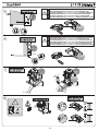
Fig. 11
Fig. 14Fig. 13
Fig. 12

- 10 -
CLICK
Fig. 15
Fig. 16
Grasso
Grease
Graisse
Fett
Gràsa
Vet
Installazione della battuta di apertura
Installing the Opening gate end stop
Installation de la butée d’ouverture
Instalación del golpe de apertura
De opening halte installeren
IT
GB
FR
DE
ES
NL
IT
GB
FR
DE
ES
NL

- 11 -
MICRO DI FINECORSA (necessari per braccio con guida scorrevole e indicati per cancelli in materiale leggero quale legno, alluminio, pvc, ...)
prima togliere alimentazione elettrica, quindi inserire il connettore, ridare alimentazione elettrica ai
(a pag. 20).
ENDSCHALTER (erforderlich bei Arm mit Gleitschiene, geeignet für Tore aus leichtem Material wie Holz, Aluminium, PVC, ...)
Zum Freischalten der Endschalter muss zunächst die Stromversorgung unterbrochen werden, dann den Steckverbindereinfügen, die Stromversorgung
an der E-Steuerungen wiederherstellen und schließlich Bart 350 programmieren (auf S. 20).
LIMIT SWITCH MICROSWITCHES (necessary for the arm with sliding guide and recommended for gates in light materials such as wood,
aluminium, PVC, etc.) To enable the limit switch microswitches, , then insert the connector, restore electrical power
(on pg. 20).
MICRO DE FIN DE CARRERA (necesarios para brazo con guía corrediza e indicados para puertas de exteriores realizadas en material ligero
como madera, aluminio, pvc, ...) antes cortar la alimentación eléctrica, por tanto introducir el
conector, volver a dar alimentación eléctrica a los programadores y por último realizar siempre una programación del Bart 350 (en pág. 20).
MICRO DE FIN DE COURSE (nécessaires pour le bras avec rail de guidage et conseillés pour des portails en matériau léger tel que le bois,
l’aluminium, pvc, ...) avant tout de couper l’alimentation électrique et ensuite d’insérer le
connecteur (à la page 20).
EINDAANSLAGEN (voor de arm op geleider en voor lichte poorten van hout, aluminium, pvc, ...)
Om de eindaanslagen te kunnen activeren, moet u eerst de elektrische voeding deactiveren en vervolgens de connector aanbrengen, de elektrische
voeding van de programmeereenheden heractiveren en de Bart 350 programmeren (zie pag. 20).
Fig. 17
IT
GB
FR
DE
ES
NL

- 12 -
CLICK
CLICK
CLICK
IL MICRO SUPERIORE È QUELLO DI INTERVENTO IN BATTUTA DI CHIUSURA
THE UPPER MICROSWITCH
IS RESPONSIBLE FOR CLOSING END STOP
LE MICRO SUPERIEUR
EST CELUI QUI INTERVIENT EN BUTEE DE FERMETURE
DER OBERE MIKROSCHALTER
IST DER, DER AM
SCHLIESSANSCHLAG EINWIRKT
EL MICRO SUPERIOR ES AQUEL DE INTERVENCIÓN EN TOPE DE CIERRE
DE MICROSCHAKELAAR BOVEN FUNGEERT ALS AANSLAG TIJDENS HET SLUITEN
IL MICRO INFERIORE È QUELLO DI INTERVENTO IN BATTUTA DI APERTURA
THE LOWER MICROSWITCH
IS RESPONSIBLE FOR OPENING END STOP
LE MICRO INFERIEUR
EST CELUI QUI INTERVIENT EN BUTEE D’OUVERTURE
DER UNTERE MIKROSCHALTER IST DER, DER AM ÖFFNUNGSANSCHLAG EINWIRKT
EL MICRO INFERIOR ES AQUEL DE INTERVENCIÓN EN TOPE DE APERTURA
DE MICROSCHAKELAAR ONDER FUNGEERT ALS AANSLAG TIJDENS HET OPENEN
IT
GB
FR
DE
ES
NL
IT
GB
FR
DE
ES
NL

- 13 -
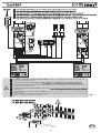
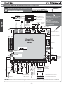
GENERAL INFORMATION REGARDING ELPRO 35M and ELPRO 35S
English
Before powering the system, perform all electrical connections of safety,
control and signalling devices described in the following pages:
ATTENTION: AL GREEN LEDS MUST REMAIN ON, AND RED LEDS MUST SWITCH ON
ONLY UPON IMPULSE.
L1 (green on) =
L2 (green on) =
L4 = Open, lights up with the opening command impulse
L5 = Close, lights up with the closing command impulse
L6 (green on) =
L7 = Radio, lights up with each transmitter impulse
L10 =
L20 = Pedestrian opening, lights up with the open command for pedestrians
L21 (green on) = NC safety contact at opening
L22 (green on) = 2nd Bart 350 Slave input
LP = Program led, it lights on in phase of programming
LINK (green on) = Connections on ABCD Master-Slave terminals are correct. With only one Bart 350 installed, terminals
A-C and B-D are correctly bridged.
Elpro 35M on board
the Bart 350 Master
FCC
FCA
ELPRO 35S DIAGNOSTIC LED
LINK (green on) = Connection made on Elpro 35M
PWR (green on) = Board on voltage Elpro 35S on board the Bart 350 Slave
DIP-SWITCHES: enable the performance of all of the possible functions of the Bart 350 Master and Slave gate opener
1 = OFF: Photocell does not stop gate in opening
2 = OFF: 3-7 Radio contact stops and reverses in opening
3 = OFF: Semiautomatic operation
4 = OFF:
5 = OFF: 3-7 radio contact reverses direction on every impulse
6 = OFF: Standard operation
7 = OFF: Blank
8 = OFF: Flasher (contact 11-12) on in pause
9 = OFF: No closing after passage by the photocell
10 = OFF: No DSA control on the photocells
11 = OFF: Bart 350 Master installed on the Left
12 = OFF: Bart 350 with articulated arm
1 = ON: Photocells stop gate in opening
2 = ON: 3-7 radio contact does not reverse (and does not stop)
in opening
3 = ON: Close in automatic after pause time
4 = ON:
5 = ON: 3-7 radio contact step by step: open-stop-close-stop
6 = ON: Decreases sensitivity of closing end stop
7 = ON: Free
8 = ON:
9 = ON: Closing after passage by the photocell
10 = ON: DSA Photocell control before start up (DSA function)
11 = ON: Bart 350 Master installed on the Right
12 = ON: Bart 350 with sliding guide (requires limit switch)
OFF
LED on: limit switch not engaged
ON
DIAGNOSTIC LEDS ON ELPRO 35M:
IMPORTANT: THE GREEN LEDS MUST ALWAYS BE ON !!
ATTENTION !!
The installation of this product must be performed by professionally trained and qualified personnel according to the safety regulations in force. It
is important to carefully read and follow the instructions so as to avoid incorrect use of this same product. The ELPRO 35M and ELPRO 35S electronic
programmers were conceived and manufactured for the management of Bart 350 electromechanical operators with 24Vdc motors.
Any other use dierent from that specified in this instruction booklet is to be considered prohibited.
ATTENTION !!
Meccanica Fadini Company declines any responsibility for damages caused to properties and/or people due to any improper installation or the lack of
bringing the system to compliance with the laws and regulations in force. The application of the Machine Directive 2006/42/CE is required. All of the
maintenance and/or test operations of the status of the product must be performed by professionally trained and qualified personnel.
ATTENTION !!
Before carrying out any procedure on the board, disconnect the electrical power supply mains.
It is furthermore recommended that the Safety Regulations made available by Meccanica Fadini be examined thoroughly.
General description: The Elpro 35M is a card with microprocessor for the command and management of the Bart 350 Master and, through Elpro 35S,
corresponding to the 2006/95/CE Low Voltage directive and the 2004/108/CE Electro-magnetic Compatibility Directive.
Operation logic: given the Open command impulse, it performs the function for open, pause, close in automatic or semi-automatic mode with
casing for the gate opener status signal.

- 14 -
GENERAL INFORMATION REGARDING ELPRO 35M and ELPRO 35S
English
Elpro 35M
on BART 350
Master
NOTE WELL:
The LEDs shown here are in the normal state for the
proper functioning of the ELPRO board.
The green LEDS should be always on.
LED on
LED flashing
LED off
IMPORTANT: the programmer recognises
the limit switches upon connector
insertion. Every time the connector is
inserted or removed,
YOU MUST:
1) REMOVE AND THEN RESTORE
ELECTRICAL POWER AFTER A FEW
SECONDS
2) PROGRAM BART 350
Terminals
with fuse
External power supply
230V 50Hz ± 10%.
For distances longer
than 50 m increase
wire sq. section.
Encoder
24V motor
Motor
Opening Limit
switch LED
Limit switch connector
Closing limit switch LED
Plug-on radio
connector
Trimmer
PAUSE
BART MASTER
TORQUE Trimmer
BART SLAVE
TORQUE Trimmer
Programming button
microprocessor
power
BART 350
SLAVE 3x1.5
Unlocking
handle
switch
Courtesy lamp
relay output
max 24V 50mA
Internal
receiver
photocell
External
receiver
photocell
Communication with Elpro 35S
of Bart 350 Slave on the second
gate (opening delayed), pg. 16
LED lamp
24Vdc output for max load 500mA:
2 pairs of photocells
1 Radio receiver
1 Chis 37 /Chis E37 LED or DGT61 board
5A
Transformer
F1= 6.3A
Bart 350 Master
F1= 6.3A
Bart 350 Slave
24V AC/DC output for Tx
photocell used for DSA
control
COMMON
Dip-Switch
OPEN
CLOSE
STOP
radio contact
Pilot light 24V - 1W
Output 24Vdc/DC
230V22V
OFF ON
FCA
FCC
BLACK
WHITE
NOTE WELL: All of the possible connections to the programmer terminal boards are also illustrated in the respective instructions sheets for each individual
accessory.
ATTENTION: USING NON-FADINI ACCESSORIES MAY DAMAGE
THE BOARD. USE ONLY CLEAN CONTACTS WITH NO-NC INPUTS.
BRIDGE ALL UNUSED NC CONTACTS
Common
Pedestrian
8,2 kΩ or NC
8,2 kΩ or NC
safety edge in
opening
safety edge in
closing
Installation for a
single gate
bridge
A-C and B-D
LINK

- 15 -
English
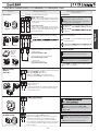
ELECTRICAL CONNECTIONS to the TERMINALS and THEIR FUNCTIONS
Seen from inside the gate:
ON: stops gate on opening and reverses it on
closing once obstacle is removed
OFF: no stop on opening, gate is reversed on
closing in case of an obstacle
ON: Does not reverse and does not stop in opening
OFF: In opening always stops and reverses
ON:
OFF:
ON: DSA control of the photocells. The photocell
projectors, outputs 13-14, must be powered
OFF: No DSA control on the photocells
L7 red O= no RADIO contact, it lights up by
any radio contact pulse
ON: Step by step with intermediate stop
OFF: Reverses direction on every RADIO pulse
ON: Flasher deactivated during Pause in
automatic operation mode (Dip 3 = ON)
OFF: Flashes during Pause in automatic mode
(Dip 3 = ON)
L1 green On
of obstacle
L2 green On
of obstacle
L4 red O = no contact OPEN, it lights up with
each opening pulse
L5 red O = no contact CLOSE, it lights up with
each closing pulse
L6 green On
by pulsing stop contact
By connecting any NO contact to the two
terminals, each pulse can perform:
- Only opening:
Dip 2=ON and Dip 5=OFF
- Reverse direction on each impulse
Dip 2=OFF and Dip 5=OFF
- Step by Step:
Open-Stop-Close-Stop
Dip 2=OFF and Dip 5=ON
Output for a possible automation status warning lamp:
Warning Lamp On= Gate Open
Warning Lamp O= Gate Closed
Flashing at 0.5s (fast)= closing movement
Flashing at 1s (normally)= opening movement
24Volt output for powering photocell projectors
(powered in parallel), for DSA control:
Device for Safety Autotest= before each movement
of the gate, if this function is enabled, all safety
accessories are checked to make sure that they are
free of obstacles, should they not, there is no start and
an error will be signalled on Bart 350 with a light that
turns to amber.
DIP-SWITCH 1:
DIP-SWITCHES 2 and 5 (MUST NEVER be
simultaneously ON):
DIP-SWITCH 4 and 8:
DIP-SWITCH 10:
2
4
10
5
8
1
24V AC/DC Output
for DSA control:
24Volt dc Flasher:
24V Output:
Warning Lamp
Output
24V- 1W:
Radio Contact:
Key-switch:
Photocells:
NO and NC contacts to be connected to the
respective terminals of the key or button-
switches.
to their respective command accessories
24Vdc output for max load 500mA:
2 pairs of photocells
1 Radio receiver
1 Led key-switch Chis 37 / Chis E37 or DGT 61 board
All the instructions are attached to their respective
command accessories
Photocell projectors
Accessory Electrical connections Dip-switches and LED indication
of their functions
ZERO.DGT
ZERO.K
ZERO.PH
ZERO.SAPE
receiver
ZERO.EK
Orbita 57
Receivers:
Astro 43
Jubi 433
Siti 63
Birio 868
External photocells:
all NC contacts of external photocell receivers
must be connected in series to terminals 1 and
2: when obstructed, the gate will re-open, if in
closing phase
Internal photocells:
all NC contacts of internal photocell receivers
must be connected in series: when obstructed,
the gate is stopped in opening, closing and
pause until cleared.
COMMON
OPEN
COMMON
CLOSE
STOP
RADIO
CONTACT
internal external

- 16 -
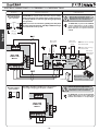
GENERAL INFORMATION REGARDING ELPRO 35M and ELPRO 35S
English
ELECTRICAL CONNECTIONS to the TERMINALS and THEIR FUNCTIONS
ATTENTION: the only electrical connections 3x1,5 and 4x0,5
between the two boards allow the Elpro 35 M programmer
to dialogue with the second Slave gate during programming
and operation.
All the accessories for command, signalling and safety must
be connected to the terminals of the Elpro 35M that manages
and controls the entire system.
Refer to the previous pages for the
Dip-Switch arrangements relative to the
individual accessories and functions
Connections for 2
Bart 350 swinging
gate operators
Connections for 1
Bart 350 swinging
gate operator
Master Slave
Accessory Electrical connections Dip-switches and LED indication
of their functions
BLACK
WHITE
Motor 24V
Bart Slave
The GREEN LEDs, in particular the LINK LED
on Elpro 35M, must be on: this conrms
proper communication between the Bart
Master and Slave on respective terminals
A-B-C-D
n°3 x 1,5
n°4 x 0,5
Master
The GREEN LEDs, in particular the LINK LED
on Elpro 35M, must be on: this conrms that
terminals A-C and B-D are correctly bridged
NOTE WELL: when Bart 350 Master is to be mounted
onto a single swinging gate bridge A-C and B-D.
microprocessor
Elpro 35M
on Bart 350
Master Motor
LINK
Elpro 35M
on Bart 350
Master
LINK
Bart Slave
release lever
switch
FCA= Bart Slave opening
limit switch LED
FCC= Bart Slave closing
limit switch LED
Bart Slave
limit switch
connector
Elpro 35S
on Bart 350
Slave
For installation and
adjustment of limit switch
microswitches, see pg. 11
LED lamp
Refer to the previous pages for the
Dip-Switch arrangements relative to the
individual accessories and functions

English
- 17 -
Safety edge
input
in Opening
Safety edge
input
in Closing
Common
Common
SAFETY EDGES
There are two separated inputs dedicated to safety edge control, one for opening and one for closing respectively. Identication by Elpro 35M board occurs
during the programming phase.
Thanks to a dedicated micro-controller circuit, separately tted on to the board, the actual integrity and correct functioning of the safety system is constantly
controlled. Any possible fault or loss of eciency is signalled by L21 and L22 LEDs ashing.
In case any of the safety edges detects an obstacle, gate travel is reversed for a bit so that obstacle can get loose.
In series if safety edges
are mechanical, N.C.
In parallel if safety edges
are resistive 8,2 kΩ
8,2 kΩ
8,2 kΩ
Common
Common
In series if safety edges
are mechanical, N.C.
In parallel if safety edges
are resistive 8,2 kΩ
L21
L22
ELECTRICAL CONNECTIONS to the TERMINALS and THEIR FUNCTIONS
Accessory Electrical connections Dip-switches and LED indication
of their functions
Accessory Electrical connections Dip-switches and LED indication
of their functions
Common
Pedestrian
Output for courtesy
lamp relay 24V 50mA
Pedestrian opening
on Bart 350 Master
NO input for external contact
for pedestrian opening on the
Bart 350 Master gate
Output for courtesy lamp relay
max 24V 50mA
L20 red O= lights up at every pedestrian
opening pulse
Normally alight:
whenever the safety edge is engaged,
the LED goes o.
Normally alight:
whenever the safety edge is engaged,
the LED goes o.

- 18 -
GENERAL INFORMATION REGARDING ELPRO 35M and ELPRO 35S
English
6
FUNCTIONS: DESCRIPTION of the FUNCTIONS of the BART 350 with articulated arm
Description Dip-switches and LED indication
of their functions
ADJUSTMENT OF TORQUE:
The adjustment of the torque by the Trimmer must be sucient to move the gate.
Before programming, it is advisable to position the Trimmer in proportion to the weight and length of the
gate. This adjustment also determines the torque on slowing down and impact resistance with an obstacle.
Too high torque in relation with the inertia of the gate leads to incorrect installation according to safety standards
EN 12445 and EN 12453. Therefore, once the torque applied to the automated gate is adjusted, the installer must
check the torques as determined by the regulations EN 12445 and EN 12453 documented in the “Safety Standards”
manual that the manufacturer provides on request.
ATTENTION: each variation on the Dip-Switches for the required functions will be executed with the next opening or
closing command.
Closing on passing through the pair of photocells:
This function enables automatic closing 3s after passage through the pair of internal
photocells
DSA: Checks photocells before start up
Device for Safety Autotest = before every gate movement, if this function is enabled
and photocell projectors outputs 13-14 are powered, a check is performed of all
safety devices to ensure they are free from obstacles. If they are not, the gate opener
alternatively.
Opening by way of External clock:
Connection: connect the NO contact of the Clock to terminal 4 OPEN and terminal 3
COMMON in parallel, and enable the automatic closing by Dipswitch 3= ON.
Operation: program the opening time on the clock.
other commands (not even radio) until the time that has been set on the clock runs
out. Once that time has expired, after the pause time, the automatic closing will
follow.
Automatic / Semiautomatic:
Automatic cycle: upon open command, the gate opens, stops in pause (for the
time set in the Pause Trimmer), then recloses automatically.
Pause time is resumed upon passage on the external photocells.
Semiautomatic Cycle: with an open command the gate moves to opening. To close
the passage, it is necessary to give the close command.
Reverse direction upon contact with obstacle:
This function enables the inversion of the movement on contact with an obstacle.
- Opening phase: the function reverses the direction, freeing the obstacle. Gate
stopped, waiting for a new command.
- Closing phase: the function reverses the direction up to the opening limit switch.
The sensitivity of the function is proportional to the torque as set by the Master and
Slave Torque Trimmer
Please note: If the gate detects an obstacle for 5 consecutive times during a
complete open - stop - close cycle, the gate will remain open and the lamp will
flash with a Blue light. Waiting for a command.
ON: Closes in Automatic Mode
OFF: Semiautomatic
ON: Enables the automatic closing after the
passage through the pair of photocells
OFF: No automatic closing
ON: DSA control of the photocells. The
photocell projectors outputs 13-14 must be
powered
OFF: No DSA control on the photocells
Pause Trimmer: the pause time
can be adjusted in the automatic
mode from 1s to 120s.
DIP-SWITCH 3:
DIP-SWITCH 6:
DIP-SWITCH 9:
DIP-SWITCH 10:
3
PAUSE
9
10
3
ON: Decreases sensitivity on closing gate stop,
to prevent the gate travel from being reversed
too easily in case of incorrect installations.
Torque Trimmer of Bart Master (M):
adjusts the torque applied on
the gate by the Bart Master and,
in proportion, the resistance to
contact with an obstacle.
Torque Trimmer of Bart Slave (S):
adjusts the torque applied on
the gate by the Bart Slave and,
in proportion, the resistance to
contact with an obstacle.
External clock
COMMON
OPEN
COMMON
ON: Closes in Automatic Mode
NO

English
- 19 -

- 20 -
GENERAL INFORMATION REGARDING ELPRO 35M and ELPRO 35S
English
BEFORE PROGRAMMING, CHECK...
1) Correctly select Dip 11 on Elpro 35M for Bart 350 Master installation on the Right
(DX) or on the Left (Sx), as seen from inside.
2) Adjust the opening gate stops (pg.10) or enable limit switches (pg.11).
3) All GREEN LEDs MUST ALWAYS BE ON, otherwise check all NC safety contacts.
4) Check if the LINK LEDS in Elpro 35M and Elpro 35S are on, otherwise verify connection
to terminals 15-16-17-18.
IMPORTANT:
ELPRO 35M has the function of self-programming or manual programming:
- SELF-PROGRAMMING:
Recommended for systems with single gates (in this case, bridge terminals A-C and B-D), or for gates without gate overlap. The entire
opening and closing of one or both one gates, including slowdown before limit switch end stops, is left to the electronic board. This
operation is performed only with one pulse, and the programmer manages all gate movements.
Please note: Self-programming is recommended for gates which do not require an opening delay or are not equipped with an electric
lock.
Recommended for gates which overlap or have an electric lock on Bart 350 Master.
NOTE:
When mains power is present, all green LEDs on the
Elpro 35M and Elpro 35S must always be on.
If the green LEDs are not all on, check each electrical
connection before continuing with programming.
General information on programming:
- Any time a change is made to the gate stop position,limit switch cam, control board or to any of its component, you must reprogram gate
opening and closing with the same procedure.
- Even in the absence of mains power, programming is always stored. During the rst cycle after a black-out, the Bart will automatically search
for the rst end stop or limit switch at slow speed.
- During all programming phases, all control and safety accessories are deactivated. The utmost care is therefore recommended.
ONLY STOP CONTACTS 3-6 AND RADIO CONTACT 3-7 ARE ENABLED ONLY FOR MANUAL PROGRAMMING PULSES
IMPORTANT: adjust the torque trimmer according to the
type of material and inertia of the gate...
Lock the gate: pg.23 “Operations for restoring gate locking”.
Remove the power fuse on Bart 350 Master and power the system...
...low torque (maximum position three) is recommended for
light or deformable gates (in aluminium, wood, PVC, etc.)
ON: Decreases sensitivity on closing gate stop, to
prevent the gate travel from being reversed too
easily in case of incorrect installations.
min
LP LP LP
min
min
GREEN LEDs
on
Bart 350 MASTER
Bart 350 SLAVE Bart 350 MASTER
RED LEDs
o
min
max
On slow
4-5 sec
max
maxmax 6
MASTER
SLAVE
Bart 350 Master locked
Bart 350 Slave locked
Remove the power
fuse present only on
the Bart 350 Master.
with the programming button pressed, insert the line fuse, after 4/5 seconds, release the programming button: the LP LED will
remain on, conrming that programming is in progress
ELPRO 35M
La pagina si sta caricando...
La pagina si sta caricando...
La pagina si sta caricando...
La pagina si sta caricando...
La pagina si sta caricando...
La pagina si sta caricando...
La pagina si sta caricando...
La pagina si sta caricando...
-
 1
1
-
 2
2
-
 3
3
-
 4
4
-
 5
5
-
 6
6
-
 7
7
-
 8
8
-
 9
9
-
 10
10
-
 11
11
-
 12
12
-
 13
13
-
 14
14
-
 15
15
-
 16
16
-
 17
17
-
 18
18
-
 19
19
-
 20
20
-
 21
21
-
 22
22
-
 23
23
-
 24
24
-
 25
25
-
 26
26
-
 27
27
-
 28
28


Fadini Bart 350 Instructions Manual
- Tipo
- Instructions Manual
- Questo manuale è adatto anche per
in altre lingue
- English: Fadini Bart 350
- español: Fadini Bart 350
- Nederlands: Fadini Bart 350
Documenti correlati
-
Fadini bart350 Instructions Manual
-
-
-
-
-
-
-