ROBBE Dark Knight EP 2036 Operating Instructions Manual
- Categoria
- Giocattoli telecomandati
- Tipo
- Operating Instructions Manual

Dark Knight
EP
No. 2036
Betriebsanleitung
Operating instructions
Notice d´utilisation
Istruzioni d’uso
Manual de Uso

Dark Knight EP
2
2036
No.
Technische Daten
Länge: ca. 400 mm
Breite: ca. 320 mm
Radstand: ca. 270 mm
Gewicht: ca. 1600 g
Verehrter Kunde,
Sie haben sich für ein vormontiertes Modellfahrzeug mit Elektromotor aus dem Hause robbe
Modellsport entschieden.
Um Ihnen den sicheren Betrieb dieses Modells zu erleichtern, sollten Sie unbedingt die bei-
liegenden Informationen vor der ersten Inbetriebnahme genau durchlesen.
Alle Positionsangaben sind in Fahrtrichtung zu sehen.
Erfor
derliches Zubehör Bestell Nr.
Fernsteuerung Attack T
-2ER F2211
oder
Fernsteuerung Megatech T-2PHKA F2223
oder
Fernsteuerung Megatech T
-2PL F2206
NC-Zelle 1,2 AA, 8x für Sender 8004 oder 8005
Fahrtregler rookie 25 8401
Fahrakku 6N C2,4 TAM 4613
Ladegerät Power Peak Fun 8467
Bau- und Betriebsanleitung
Bei der Vorbereitung des Modells richten Sie sich bitte nach dieser Anleitung.
Hinweise: Zur Vermeidung von Verletzungen ist besondere Vorsicht im Umgang mit den erfor-
derlichen Werkzeugen und Bauteilen des Modells geboten.
Es empfiehlt sich, die Anleitung aufzuheben, um bei Reparaturen und Ersatzteilbestellungen
nachschlagen zu können.
Eine Gesamtübersicht der Ersatzteile und Tuningteile finden Sie auf den Seiten 16 - 23
Specification
Length: ap. 400 mm
Width: ap. 320 mm
Wheelbase: ap. 270 mm
Weight: ap. 1600 g
Dear customer,
Congratulations on your choice of a factory-assembled electric-powered model car from the
robbe Modellsport range.
To make it easier for you to operate this model safely and reliably please be sur
e to read the
information sheets included in the pack before operating the car for the first time.
All directions (e.g. „right-hand“) are as seen from the rear of the car looking forward.
Essential accessories Order No.
Attack T-2ER radio contr
ol system F2211
or
Megatech T-2PHKA radio control system F2223
or
Megatech T
-2PL radio control system F2206
1.2 AA NC cell 8004 or 8005
8 cells required for transmitter
rookie 25 speed controller 8401
Drive battery 6N C2,4 TAM 4613
Battery charger Power Peak Fun 8467
Assembly and operating instructions
Please follow these instructions when preparing the model.
Note: to avoid injury please take special care when handling the tools and model components.
We recommend that you keep these instructions in a safe place so that you can refer back to
them for repairs and when ordering replacement parts.
Pages 16 - 23 show overall views of r
eplacement parts and available upgrade components for
the model.
Betriebsanleitung, Operating instructions

Dark Knight EP
3
2036
No.
Caractéristiques techniques
longueur: ap. 400 mm
largeur: ap. 320 mm
empattem.: ap. 270 mm
poids: ap. 1600 g
Cher Client,
Vous avez choisi un modèle réduit d’auto prémonté à moteur électrique de la Sté robbe
Modellsport.
Pour vous faciliter la maîtrise du véhicule, il est indispensable de lire les feuilles d’information
jointes avant la première mise en œuvr
e.
Toutes les indications de position sont à considérer dans le sens de déplacement du
véhicule.
Accessoires nécessaires réf.
ensemble de radiocommande Attack T-2ER F2211
ou
ensemble de radiocommande Megatech T-2PHKA F2223
ou
ensemble de radiocommande Megatech T-2PL
F2206
éléments Cd-Ni 1,2 AA, 8x pour l‘émetteur 8004 ou 8005
variateur rookie 25 8401
accu du moteur 6N C2,4 TAM 4613
Chargeur Power Peak Fun 8467
Notice d’assemblage et de mise en service
Pour la préparation du modèle, suivre les instructions présentées par cette notice.
À noter : pour éviter toute blessure, il est recommandé d’être particulièrement prudent en ce
qui concer
ne la manipulation des outils nécessaires et des composants du modèle.
Il est conseillé de conserver les différentes notices du modèle et de ses composants afin de
pouvoir les consulter en cas de réparation et de commande de pièces de rechange.
Vous trouverez une vue d’ensemble des pièces de rechange et accessoires de compétition sur
les pages 16 à 23.
Dati tecnici
Lunghezza: ca. 400 mm
Larghezza: ca. 320 mm
Passo: ca. 270 mm
Peso: ca. 1600 g
Gentile acquirente,
congratulazioni per aver scelto un automodello premontato a motore elettrico, appartenente
alla famiglia di modelli della robbe Modellsport.
Raccomandiamo tassativamente di leggere con attenzione l’intero manuale per l’uso prima di
utilizzar
e il modello per la prima volta. Tale accorgimento consente di semplificare e rendere
più sicuro l’utilizzo di questo modello.
Tutte le indicazioni riguardanti le posizioni (es: “destra) sono da intendersi rispetto alla dire-
zione di marcia.
Accessori consigliati: Art.N.
Trasmittente Attack T-2ER F2221
oppure
Trasmittente Megatech T-2PHKA
F2223
oppure
Trasmittente Megatech T-2PL
F2206
Celle NC 1,2 AA, 8xtrasmittente 8004 oppure 8005
Regolatore di velocità rookie 25 8401
Batteria di alimentazione
modello 6N C2,4 TAM 4613
Caricabatteria Power Peak Fun 8467
Istruzioni di montaggio, istruzioni per l’uso
Durante la preparazione del modello, fare riferimento al presente manuale di istruzioni
Avvertenze:al fine di evitare incidenti e lesioni, si raccomanda vivamente di maneggiare con
cautela gli attr
ezzi e i componenti dell’automodello.
Si consiglia di conservare il presente manuale come riferimento per eventuali riparazioni o
elenco e codifica per le parti di ricambio.
Consultare le pagine 16 - 23 per l’elenco generale delle parti di ricambio e delle parti di ela-
borazione.
Notice d’utilisation, Istruzioni d’uso

Dark Knight EP
2036
No.
4
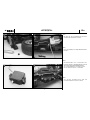
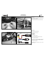
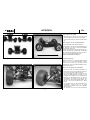
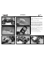
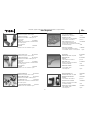
Bild 1
- Die Räder auf die Sechskantmitnehmer aufstecken
und mit den M 4-Radmuttern festsetzen.
Bild 2
- Regler und Empfänger mit Doppelklebebandstreifen
befestigen
Bild 3
- Servohebelschraube lösen, Steuerscheibe bzw.
Kr
euzhebel abnehmen. Anschließend das Servo mit
der Fernsteuerung in Neutralstellung bringen.
-
Servo mit Gummitüllen bzw. Unterlagen versehen.
- Die Servohalter am Lenkservo verschrauben.
Bild 4
- Servo einsetzen. Servohalter mit den Senk- und
Linsenkopfschrauben am Chassis montieren.
Betriebsanleitung
1
2
3
4

Dark Knight EP
5
2036
No.
Fig. 1
- Fit the wheels on the hexagon drivers and tighten the M4
wheel nuts to secure them.
Fig. 2
- Attach the speed controller and r
eceiver using strips of
double-sided foam tape.
Fig. 3
- Undo the servo output screw and remove the standard
output disc or cruciform output lever. Set the servo to
centre from the transmitter.
-
Press the rubber grommets and bushes into the servo
mounting lugs.
- Screw the servo mounts to the steering servo.
Fig. 4
- Install the servo. Fix the servo mounts to the chassis using
the countersunk screws and pan-head scr
ews supplied.
Fig. 1
- Planter les roues sur l'entraîneur six pans et les y fixer avec
les écrous de roue M 4
Fig. 2
- Fixer le variateur et le récepteur avec des morceaux de
ruban adhésif double face.
Fig. 3
- Desserrer et r
etirer la vis de palonnier du servo, retirer le
palonnier circulaire ou le palonnier en croix du servo.
Amener ensuite le servo au neutre à l'aide de l'ensemble
de radiocommande.
- Munir le servo des passe-fils ou de cales.
-
Visser les éléments du support-servo au servo de direc-
tion.
Fig. 4
- Mettr
e le servo en place. Monter le support-servo au châs-
sis avec les vis à tête fraisée et les vis à tête bombée.
Fig. 1
- Inserire le ruote negli appositi trascinatori esagonali, quin-
di fissarle in posizione avvitando i dadi esagonali M 4con
flangia.
Fig. 2
- Fissare il regolatore di velocità e la ricevente sul modello
mediante del nastro biadesivo.
Fig. 3
- Svitare la vite di fissaggio della squadretta del servo per
poter rimuovere quest’ultima. Centrar
e il servo (posizione
“neutro” = metà corsa) mediante la trasmittente.
- Equipaggiare il servo con gli appositi inserti in gomma e le
rondelle.
- Fissare le colonne di supporto sul servo dello sterzo.
Fig. 4
- Posizionar
e il servo sul modello, quindi fissare le colonne
di supporto al telaio serrando le apposite viti a testa sva-
sata e a testa sferica.
Operating instructions instructions, Notice d’utilisation, Istruzioni d’uso

Dark Knight EP
2036
No.
6
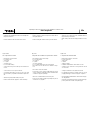
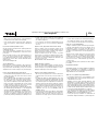
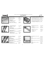
Bilder 5 und 6
- Die Litzenantenne des Empfängers abwickeln und in das
Antennenröhrchen einfädeln.
- Das Antennenröhrchen in den Antennenfuß einsetzen.
Bilder 7 und 8
Die RC-Komponenten im Modell
-
M: Elektronischer Fahrtregler
- N: Lenkservo
- O: Empfänger
-
P: Quarz
- Q: Elektromotor
- R: Sechszelliger Fahrakku
- Lenkservo und Regler am Empfänger anschließen.
- Motor am Regler anschließen.
- Zum Einbau des geladenen Fahrakkus die Splinte am
Akkufach lösen und den Kunststoffhalter wegziehen.
- Den Fahrkku einschieben.
- Den Akku mit dem eingesetzten Halter und den
Splinten sichern.
Betriebsanleitung
7
8
5
6
O
M
N
P
Q
R

Dark Knight EP
7
2036
No.
Figs. 5 and 6
- Unwind the wire aerial attached to the receiver and slip it into
the plastic aerial sleeve.
- Push the aerial sleeve into the aerial socket as shown.
Figs. 7 and 8
RC components in the model
- M: Electr
onic speed controller
- N: Steering servo
- O: Receiver
-
P: Crystal
- Q: Electric motor
- R: Six-cell drive battery
- Connect the steering servo and the speed controller to the
receiver.
- Connect the motor to the speed controller.
- To install the drive battery you have to remove the split
pins in the battery compartment and lift off the plastic hol-
der.
- Slide the fully-charged drive battery into place.
- Re-fit the holder and the split pins to retain the battery.
Figures 5 et 6
- Déployer l’antenne souple du récepteur et l’enfiler dans le
tube-guide d‘antenne.
- Planter le tube-guide d’antenne dans le pied de l‘antenne.
Fig. 7 et 8
Composants de l’ensemble de réception dans le modèle
- M: variateur de vitesse électronique
- N: servo de direction
-
O: récepteur
- P: quartz
- Q: moteur électrique
- R: accu d’alimentation du moteur à six éléments
- Raccorder le servo de direction et le variateur au récep-
teur.
- Raccorder le moteur au variateur.
- Pour mettre les accus chargés d'alimentation du moteur
en place, défaire la goupille du logement de l'alimentation
et extraire le support en plastique.
- Glisser l'accu d'alimentation du moteur en place.
- Fixer l'accu en mettant le support en plastique en place et
en fixant avec les goupilles.
Figure 5 e 6
- Sfilare per intero l’antenna ricevente ed infilarla attraverso
l’apposito tubo porta-antenna.
- Infilare il tubo porta-antenna nell’apposita base di sosteg-
no.
Figure 7 e 8
I componenti RC nell’automodello
-
M: Regolatore elettronico di velocità
- N: Servo dello sterzo
- O: Ricevente
- P: Quarzo
- Q: Motore elettrico
- R: Batteria di alimentazione del modello a sei celle
- Collegare il servo dello sterzo ed il regolatore di velocità
con la ricevente.
- Collegare i fili del motor
e al regolatore di velocità.
- Per alloggiare la batteria nel modello, rimuovere la clip
(copiglia) di fissaggio ed estrarre il supporto in plastica.
- Inserire la batteria di alimentazione del modello nell’ appo-
sito alloggiamento.
- Assicurare ora la batteria in posizione posizionando il sup-
porto in plastica ed inserendo la clip di fissaggio.
Operating instructions instructions, Notice d’utilisation, Istruzioni d’uso

Dark Knight EP
2036
No.
8
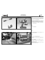
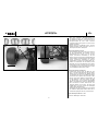
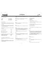
Bild 9
- Die zwei Kugelgelenke auf die M 3 Gewindestange
aufdrehen. Das so gefertigte Lenkgestänge auf eine
Länge von ca. 50 mm einstellen.
- Hinweis: Dem Montagekasten liegen Servohebel mit
verschiedenen Feinverzahnungen bei. Die Hebel für
Futaba Servos sind mit einem “F” gekennzeichnet.
-
Den Kugelkopf für die Lenkung in den einarmigen
Servohebel eindrehen.
Bild 10
-
Sender einschalten.
Bild 11
- Die Empfangsanlage durch Anschließen des
Fahrakkus einschalten.
Bild 12
-
Lenkservo in Neutralstellung bringen.
- Vorbereiteten Servohebel auf das Lenkgestänge auf-
drücken.
- Zweites Kugelgelenk auf den Kugelkopf des Servo-
Savers aufdrücken.
-
Gestänge so einstellen, dass die Vorderräder auf
Geradeauslauf stehen.
- Hebel auf das Servo stecken und mit der
Servohebelschraube sichern.
Betriebsanleitung
9
10
11
12
“A”
“B”
“X”

Dark Knight EP
9
2036
No.
Fig. 9
- Screw the two ball-links onto the M3 threaded rod to make
the steering pushrod. Set the pushrod to a length of about
50 mm.
- Note: the kit is supplied with servo output arms featuring
dif
ferent spline patterns. If you ar
e using a Futaba servo,
use the arm marked with a letter “F”.
- Screw the ball-end bolt for the steering system into a hole
in the single-arm servo output lever.
Fig. 10
- Switch on the transmitter.
Fig. 11
- Switch on the r
eceiving system by connecting the drive
battery to the speed controller.
Fig. 12
- Set the steering servo to neutral (centre).
- Press the pr
epared servo output arm onto the steering
pushr
od.
- Press the second ball-link onto the ball-end bolt on the
servo-saver.
- Adjust the pushrods so that both front wheels are at the
“straight ahead” position.
- Fit the output arm on the servo, and tighten the output
screw to secure it.
Fig. 9
- Monter les deux articulations sphériques sur la tige filetée
M 3. Régler la longueur de la tringle de direction sur une
longueur approximative de 50 mm.
- À noter : La boîte de construction fournit plusieurs palon-
niers de servo présentant une denture fine diverse. Les
palonniers destinés aux servos de marque Futaba sont
munis d'un repèr
e “F”.
- Monter le pivot sphérique de la direction sur le palonnier
de servo à un bras.
Fig. 10
- Mettre l'émetteur en marche.
Fig. 11
-
Mettre l'ensemble de réception en marche en raccordant
l'accu d'alimentation du moteur.
Fig. 12
- Amener le servo de direction en position neutre.
- Planter le palonnier de servo préparé sur la tringle de
direction.
- Planter la seconde articulation sphérique sur le pivot
sphérique du sauve-servo.
-
Régler la tringle de telle manière que les roues avant se
trouvent disposées à effectuer une course rectiligne.
- Planter le palonnier sur le servo et l'y fixer avec la vis de
fixation du palonnier de servo.
Fig. 9
- Avvitare le due articolazioni sferiche sulle due estremità
dell’asta filettata M 3. Regolare l’asta su una lunghezza
complessiva pari a 50 mm ca.
- Avvertenza: la scatola di montaggio compr
ende diverse
squadrette con dentatura di fissaggio differente. Le squa-
drette compatibili con servi Futaba sono contrassegnate
dalla lettera “F”.
- Avvitare la vite a testa sferica nella squadretta a braccio
unico per lo sterzo.
Fig. 10
- Accendere la trasmittente.
Fig. 11
- Collegare la batteria di alimentazione al r
egolatore di velo-
cità per accendere la ricevente.
Fig. 12
- Centrar
e il servo dello sterzo (posizione di “neutro”)
- Agganciare la squadretta del servo assemblata in pr
ece-
denza con il tirante dello sterzo.
- Agganciare la seconda articolazione sferica contro la vite
a testa sferica del salva-servo.
- Regolare la lunghezza del tirante in modo che le ruote
anteriori risultino parallele.
- Inserire la squadretta nel servo e fissarla in posizione
mediante l’apposita vite di fissaggio.
Operating instructions instructions, Notice d’utilisation, Istruzioni d’uso

Dark Knight EP
2036
No.
10
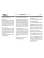
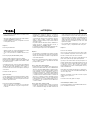
Bilder 10 und 13, die Lenkung
- Bei Betätigen des Lenkrads “A“ nach rechts (links)
müssen die Räder nach rechts (links) einschlagen.
- Ist dies nicht der Fall, Servo-Reverse-Schalter betäti-
gen.
Bilder 10 und 14, Gas (Vor
- und Rückwärtsfahrt)
Regler gemäß beiliegender Anleitung aktivieren.
Bei Vorwärtsfahrt muß die rote LED gleichmäßg leuch-
ten. Blinkt die rote LED, die Motor
-Anschlußkabel
gegeneinander vertauschen.
Befindet sich der Gashebel “B” in Vorwärtsstellung “X” ,
muß der Fahrtregler im Vorwärtsbetrieb sein (Die LED
darf nicht blinken). Andernfalls muß im Sender Servo-
Reverse für den Gaskanal betätigt werden.
Damit ist das Fahrzeug betriebsbereit.
Fahrwerkseinstellungen:
Hinweis: Das Chassis ist werksseitig grundeingestellt.
Wenn Sie sich mit den Fahreigenschaften vertraut
gemacht haben, können Sie das Modell durch
Veränderungen an den Fahrwerkseinstellungen auf Ihr
e
Bedürfnisse abstimmen.
Bilder 15 und 16, Einstellen der Stoßdämpfer:
- Beachten Sie, daß alle folgenden Einstellungen an
beiden Seiten einer Achse durchgeführt werden müs-
sen, um den beschriebenen Effekt zu erzielen.
-
Durch Verwendung von Ringen verschiedener Höhe
auf dem Stoßdämpferzylinder verändern Sie die
Bodenfreiheit des Modells, nicht die Federhärte. Die
Einstellung der Bodenfreiheit richtet sich nach der
Beschaffenheit des befahrenen Untergrundes und
sollte immer möglichst gering gehalten werden, ohne
daß das Chassis beim Durchfedern den Boden
berührt.
- Die Federhärte können Sie durch den Austausch der
serienmäßigen Federn gegen die Ø 1,3mm
Tuningfedern No. 2028026 (vorn) und No. 20280027
(hinten) verändern.
- Am einfachsten lässt sich die Federcharakteristik
Betriebsanleitung
13
14
15
16
+ / -

Dark Knight EP
11
2036
No.
Fig. 10 and 13, steering
- When you move steering wheel “A“ to the right (left) the
front wheels must also deflect to the right (left).
- If the steering works the wrong way r
ound, operate the
servo reverse switch „F“ under the battery compartment
cover.
Fig. 10 and 14, throttle (forward / reverse)
Arm the controller as described in the operating instructions
supplied with the unit.
The red LED should glow constantly when you select for-
ward running. If the red LED flashes, swap over the motor
power wir
es.
When the throttle lever “B” is in the „forward running“ posi-
tion “X” , the speed controller must be in „forward“ mode,
i.e. the LED must not flash. If necessary correct this by ope-
rating the servo reverse switch „E“ in the transmitter for the
throttle channel.
The car is now ready to run.
Chassis adjustments:
Note: the chassis is factory-adjusted to suit normal opera-
ting conditions. Once you have become familiar with its run-
ning characteristics and handling you may wish to make
adjustments to the chassis settings to suit your driving style.
Figs. 15 and 16, adjusting the shock absorbers:
- Note that all the following adjustments must be carried out
at both sides (ends) of the same axle in order to achieve
the effect described.
- Rings of different height can be fitted to the shock absor-
ber cylinders. This alters the model's gr
ound clearance -
not the hardness of the suspension. Ground clearance
only needs to be adjusted to suit the surface quality of the
track you are using. It should always be set to the lowest
possible clearance at which the chassis does not quite
touch the ground at maximum suspension travel.
- The stiffness of the suspension can be altered by removing
the standard springs and fitting the 1.3 mm Ø upgrade
springs No. 20280026 (front) and No. 20280027 (rear.)
- The simplest means of adjusting the car’s suspension cha-
racteristics is to alter the mounting angle of the shock
absorbers. As supplied, the model’s shock absorbers are
positioned to provide good handling on a relatively uneven
Figures 10 et 13, la direction
- Lorsque vous tournez le volant “A“ vers la droite (la
gauche) il faut que les roues effectuent un débattement
vers la droite (la gauche).
- Si ce n’est pas le cas, actionner le dispositif d’inversion de
la course du servo „F“ sous le couvercle du compartiment
de l‘accu.
Figures 10 et 14, gaz (marche avant et marche arrière)
Activer le variateur selon les instructions fournies par la
notice jointe. En marche avant, il faut que la diode rouge soit
allumée de manière régulièr
e. Si la diode rouge clignote,
intervertir les brins de connexion du moteur.
Lorsque le manche des gaz “B” se trouve en position
marche avant “X”, il faut que le variateur asservisse égale-
ment la marche avant (la diode ne doit pas clignoter). Si ce
n’est pas le cas, actionner le dispositif „E“ d’inversion de la
course du servo des gaz.
Ainsi le véhicule est en ordre de marche.
Réglage du train de roulement :
À noter : le réglage initial du châssis est effectué à l’usine.
Une fois que vous vous êtes familiarisé avec les réactions du
modèle sur la piste, il est possible de l’adapter à vos carac-
téristiques de pilotage pour en tir
er le meilleur.
Figures 15 et 16, Régler les amortisseurs:
- Observer que les réglages décrits ci-dessous doivent être
réalisés des deux côtés de l’axe pour otenir l’effet sou-
haité.
- En utilisant des bagues de hauteur différ
ente sur le vérin
d'amortisseur, il est possible de modifier la garde au sol du
modèle mais pas la dureté de l'amortissement. La garde
au sol doit être ajustée à la configuration de la chaussée et
demeurer toujours la plus petite possible sans toutefois
que le châssis ne touche le sol en phase d’amortissement.
- Il est possible de modifier la dureté de l’amortissement en
remplaçant les ressorts de série par des ressorts de
compétition de Ø 1,3 mm, réf. 20280026 (avant) et
20280027 (arrière).
- La manière la plus simple de modifier la caractéristique
d’amortissement est de modifier l’angle de fixation des
amortisseurs. Dans l’état dans lequel ils sont livrés, les
amortisseurs sont réglés pour une chaussée relativement
Figure 10 e 13, lo sterzo
- Le ruote devono spostarsi verso destra (sinistra) azionan-
do il volantino di comando “A” verso destra (sinistra).
- In caso contrario, azionare l’interruttore “Servo-Reverse”
Figur
e 10 e 14, gas (avanti/indietro)
Collegare e attivare il regolatore di velocità seguendo quan-
to riportato nelle istruzioni per l’uso ad esso allegate. Per un
funzionamento corretto, è necessario che il LED rosso sul
regolatore sia illuminato costantemente. Se invece lampeg-
gia, allora occorr
e invertire tra loro i cavi di collegamento con
il motore.
Quando la leva di comando del gas “B” si trova in posizione
“avanti X”, occorre che il regolatore di velocità risulti in
modalità “marcia avanti” (ovvero il LED non deve lampeggi-
are). Se questo non si verifica, è necessario azionare l’inter-
ruttore “Servo Reverse” sulla trasmittente (per invertire la
corsa del servo).
Una volta completate queste operazioni, il modello è pronto
per l’utilizzo.
Regolazioni del modello:
Avvertenza: il modello vene regolato inizialmente in fabbrica.
Dopo aver familiarizzato con il pilotaggio e le reazioni del
modello, potete agire sulle regolazioni di quest’ultimo per
meglio adattarlo al vostr
o stile di guida.
Figure 15 e 16, regolazione degli ammortizzatori
- Le regolazioni seguenti devono essere effettuate su ent-
rambi i lati dello stesso asse del modello al fine di ottene-
re gli effetti ad esse associati.
- Utilizzando spessori (anelli) di altezza dif
ferente sugli
ammortizzatori è possibile variare l’altezza da terra del
modello, ma non la durezza delle molle . L’altezza da terra
viene regolata in base al terreno su cui il modello viene uti-
lizzato. E’ preferibile mantenerla sempre quanto più bassa
possibile, facendo tuttavia attenzione affinché il telaio non
tocchi il suolo mentre l’ammortizzatore è compresso.
- Per modificare la durezza delle molle è possibile sostituire
quelle in dotazione con quelle tuining Ø 1,3 mm Art.N.
20280006 (anteriori) e Art.N. 20280027 (posteriori).
- Il modo più agevole per modificare le caratteristiche di
assorbimento degli ammortizzatori, è quello di agire vari-
Operating instructions instructions, Notice d’utilisation, Istruzioni d’uso

Dark Knight EP
2036
No.
12
durch einen geänderten Befestigungswinkel der
Stossdämpfer erreichen. Im Lieferzustand sind die
Stossdämpfer des Modells so montiert, das sich die
Fahreigenschaften für einen relativ unebenen
Untergrund eignen. Man spricht von einem weichen
Dämpfungsverhalten.
- Montiert man die Stossdämpfer steiler, wird das
Dämpfungsverhalten härter und eignet sich beson-
ders für glatte und ebene Rennpisten.
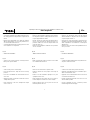
Bild 17, Einstellung der Vorspur:
- Die Einstellung der Spur an der Vorderachse wirkt sich
auf den Geradeauslauf des Modells und die
Empfindlichkeit der Lenkung aus. Bei positiver
Vorspur (schematische Darstellung 1) hat das
Fahrzeug einen besonders ruhigen Geradeauslauf und
reagiert verhalten auf Lenkbewegungen. Bei negativer
Vorspur (schematische Darstellung 2) wird der
Geradeauslauf schlechter
, das Modell reagiert emp-
findlicher auf Lenkbefehle. Im Lieferumfang ist das
Modell für einen guten Geradeauslauf und normales
Lenkverhalten mit fast neutraler Vorspur (schemati-
sche Darstellung 3) eingestellt. Veränderungen sollten
hier zurückhaltend vorgenommen werden.
Bild 18, Einstellung des Radsturzes:
- Normalerweise wird der Sturz der Räder an einer
Achse so eingestellt, daß die Reifen mit voller Fläche
aufliegen (wie im Lieferzustand des Modells). Durch
eine Verkürzung der oberen, einstellbar
en Querlenker
erreicht man einen negativen Sturz an der Achse. Dies
führt zu einer höheren Traktion bei Kurvenfahrten, da
sich das Fahrzeug „in die Kurve stemmt“, hat aber
den Nachteil, dass sich die Reifen ungleichmäßig
abfahren und aufgrund der geringeren Auflagefläche
früher verschleissen. Positiver Sturz führt zu einer
geringeren Traktion an der Achse. Bei einem Off-
Road-Modell ist somit ein neutraler oder geringfügig
negativer Sturz empfehlenswert.
- Grundsätzlich gilt, dass Veränderungen am Fahrwerk
nur schrittweise durchgeführt werden sollten und an-
schließend ausgiebig auf der Piste getestet werden.
robbe Modellsport GmbH & Co. KG
Technische Änderungen vorbehalten
Betriebsanleitung
17
1
2
3
18

Dark Knight EP
13
2036
No.
surface. This is termed soft damping characteristics.
- If you re-position the shock absorbers at a steeper angle,
the damping characteristics become stiffer; this is particu-
larly suitable for smooth, flat race tracks.
Fig. 17, adjusting toe-in:
- The toe-in setting of the front axle affects the model’s
straight running characteristics and its steering response.
With positive toe-in (drawing 1) the car has very smooth,
steady straight-running characteristics, and responds rela-
tively „softly“ to steering commands. If you set negative
toe-in (drawing 2), the car becomes less dir
ectionally sta-
ble and responds more directly to steering commands. As
supplied the model is set up with almost neutral toe-in
(drawing 3) which provides good straight running charac-
teristics and normal steering response. Any changes to
this setting should be made in small increments.
Fig. 18, adjusting wheel camber:
- The camber of the wheels on an axle is normally set so
that the full width of the tyres makes contact with the gro-
und (model as supplied). Shortening the upper adjustable
transverse arm applies negative camber to the axle. This
results in higher traction thr
ough turns, as the car „leans
into the bend“, but the drawback is that the tyres wear
faster and more unevenly since the contact area is smal-
ler. Positive camber results in reduced traction on the axle.
We therefore recommend neutral or slightly negative cam-
ber for off-road models.
- The basic rule is that any adjustments to the chassis
should always be carried out gradually, in small incre-
ments, and that the result of each change should be
tested thoroughly on the track.
robbe Modellsport GmbH & Co. KG
We reserve the right to alter technical specifications
plane. On parle alors d’un amortissement souple.
- Si on réduit l’angle d’attaque des amortisseurs, leur amor-
tissement devient plus dur ce qui l’approprie aux pistes
lisses et planes, comme les pistes de compétition.
Fig. 17, Réglage du pincement des roues avant:
- Le réglage du pincement sur l’essieu avant a un effet sur
la trajectoire rectiligne du modèle et sur la sensibilité de sa
direction. A
vec un pincement positif (représentation sché-
matique 1) l’auto offre une trajectoire rectiligne saine et
réagit avec une certaine retenue aux mouvements de la
direction. Avec un pincement négatif à l’avant (représenta-
tion schématique 2) la tenue de trajectoire rectiligne est
moins bonne et le modèle réagit très sensiblement aux
instructions de direction. Le modèle est livré avec une
bonne tenue de trajectoire et un comportement normal
aux instructions de direction avec un pincement avant pra-
tiquement neutre (représentation schématique 3).
Effectuer les réglages de manière à rester dans des limites
convenables.
Fig. 18, Réglage du carrossage :
- Normalement, le carrossage est réglé de telle manière que
les pneumatiques s’appuient de tote leur surface sur le sol
(c’est ainsi que le modèle est livré). Lorsqu’on raccourcit le
bras d’oscillation transversal du haut qui est réglable, on
obtient un carrossage négatif de l’axe concerné. Ce régla-
ge apporte une meilleure traction dans le virages, étant
donné que le modèle “se penche dans les virage ”, mais il
présente l’inconvénient d’une usur
e irrégulière des pneu-
matiques étant donné que leur surface d’appui au sol est
moindre. Un carrossage positif réduit la traction sur l’es-
sieu. Sur un modèle de tout terrain, il est donc recom-
mandé de conserver un carrossage neutre ou légèrement
négatif.
- En principe, n’effectuer les réglages sur le train de roule-
ment qu’en procédant par petites étapes contrôlées
systématiquement par de nombreux tours de piste.
robbe Modellsport GmbH & Co. KG
Sous réserve de modification technique
ando il loro angolo di fissaggio rispetto al veicolo.
La regolazione di base degli ammortizzatori,ovvero quella
con cui viene fornito il modello nella scatola è indicata per
terreni particolarmente piani e poco sconnessi. Viene defi-
nita “assetto morbido”.
- Riducendo l’angolo di fissaggio, gli ammortizzatori diven-
gono più duri; tale assetto ben si addice a piste lisce e
piane, come quelle delle competizioni.
Fig. 17, regolazione della convergenza
La regolazione della convergenza sull’asse anteriore influen-
za la reattività del modello ai comandi direzionali e la sua
capacità di mantenere una traiettoria r
ettilinea. Per con-
vergenze positive, (illustrazione schematica 1) il modello
mantiene una traiettoria rettilinea ben impostata e reagis-
ce relativamente “dolcemente” ai cambi di direzione
impartiti dal pilota. Per convergenze negative, (illustrazio-
ne schematica 2) il modello mantiene più difficilmente la
traiettoria rettilinea e reagisce più direttamente ai cambi di
direzione. Il modello viene consegnato con una conver-
genza praticamente neutra (illustrazione schematica 3),
ideale per mantenere una traiettoria rettilinea stabile ed un
comportamento normale. Ogni regolazione deve essere
effettuata poco per volta.
Fig. 18, regolazione del camber (campanatura)
- Normalmente il camber è impostato in modo che la ruota
appoggi sul suolo con tutta la sua superficie utile di con-
tatto (tale configurazione è quella impostata in fabbrica sul
modello). Accorciando il tirante superiore regolabile, si
ottiene invece un camber negativo. T
ale assetto conferis-
ce al modello maggior trazione in percorrenza di curva, dal
momento che quest’ultimo “si distende in curva”, ma ha lo
svantaggio di causare un consumo differente e prematuro
su ciascuna ruota per via della minore superficie di con-
tatto. Un camber positivo implica invece minor trazione
sull’asse. Per un automodello off-road viene pertanto rac-
comandato un camber leggermente negativo o neutro.
- Si raccomanda inoltre di effettuare le regolazioni sul cam-
ber gradualmente; l’effetto di tali regolazioni dovrebbe
essere inoltre sempre verificato con alcuni giri di collaudo.
robbe Modellsport GmbH & Co. KG
Con riserva di modifiche tecniche
Operating instructions instructions, Notice d’utilisation, Istruzioni d’uso

Dark Knight EP
2036
No.
14
Bilder 19 - 25, Karosserie
Ausschnitte und Bohrungen für Servo-Saver,
Spurstangen, Karosseriebefestigung und Antenne
anbringen.
Scheiben der Karosserie innen abkleben.
Die Karosseriebohrungen von außen mit Klebeband ver-
schließen, um ein Dur
chlaufen der Farbe zu verhindern.
Die gesamte Innenseite der Karosserie und den Spoiler
mit feinem Nassschleifpapier (Körnung 300) anschleifen.
Karosserie innen mit lauwarmem Seifenwasser reinigen,
trocknen lassen und mit rocolor PC-Lack, Bestell Nr. je
nach Farbe, lackieren. Äussere Schutzhülle abziehen.
Nach Trocknen der Farbe Klebeband abziehen.
Dekorbilder abziehen, mit Seifenwasser anfeuchten
und auf der Karosserie platzieren. Luftblasen mit einem
weichen Lappen ausstreichen.
Dekorbilder auf dem Spoiler aufbringen. Spoiler auf die
Stützen setzen und mit Splinten befestigen.
Karosserie aufsetzen und mit Splinten befestigen.
Betriebsanleitung
19
20
21
22
23
24
25

Dark Knight EP
15
2036
No.
Figs. 19 - 25, the body
Cut the openings and holes required for the servo-saver, the
steering tie rods, bodywork mounting and aerial.
Apply masking tape to the inside of the windows.
Apply tape over the outside of the bodywork openings to pre-
vent the paint running through.
Sand the whole of the inside of the bodywork and spoiler
using fine wet-and-dry paper (300-grit) to pr
ovide a “key” for
the paint. Wash out the inside of the moulding with luke-warm
soapy water and allow it to dry. The bodywork can now be
painted using rocolor PC paint, Order No. according to colour.
Peel off the external protective film. Remove the tape again
when the paint has dried.
Remove decal, make slightly wet with soapy water and
position decals on bodywork, then smooth out air bubbles
with a soft cloth.
Apply the decals to the spoiler. Place the spoiler on the sup-
ports and fix it in place using the split pins.
Place the body on the chassis and secure it with two split
pins.
Figures 19 à 25, la carrosserie
Réaliser les alésages pour le sauve-servo, les barres d’ac-
couplement, la fixation de la carrosserie et l'antenne.
Appliquer des morceaux du ruban adhésif à l’intérieur de la
carrosserie avant de la peindr
e.
Boucher les orifices de la carrosserie de l’extérieur avec des
morceaux de ruban adhésif pour éviter que la peinture y
passe.
Poncer l’intégralité de l’intérieur de la carrosserie et de
l’aileron avec du papier de verre humide (grain 300). Nettoyer
l’intérieur de la carrosserie à l’eau savonneuse tiède, la laisser
sécher avant d’appliquer la peinture rocolor PC, réf. en fonc-
tion de la teinte choisie. Retirer le film protecteur extérieur.
Retirer les morceaux avant que la peinture ne soit complète-
ment sèche.
Disposer les autocollants de décoration sur la carosserie,
après les avoir humidifier avec de l'eau tiède savonneuse.
Débarasser des bulles d’air avec un chif
fon humide.
Appliquer les autocollants de décoration. Installer l’aileron
sur les colonnettes et le fixer avec les goupilles.
Mettre la carr
osserie en place et la fixer avec 2 goupilles.
Figure 19 – 25, Carrozzeria
Realizzare sulla carrozzeria i fori e le fessure per il pas-
saggio del salva-servo, dei tiranti, dei montanti di fissaggio
e dell’antenna.
Incollare all’interno della carrozzeria le mascheratur
e per la
verniciatura.
Applicare dall’esterno del nastro adesivo per tappare i fori
della carrozzeria ed impedire alla vernice di colare.
Levigare tutta l’area interna della carrozzeria e dello spoiler
con della carta abrasiva umida fine (grana 300). Pulire quin-
di l’interno della carrozzeria con acqua e sapone tiepidi,
lasciare asciugare, quindi verniciare dall’interno mediante
vernici a spruzzo robbe rocolor (l’Art. della vernice varia in
base al colore prescelto). Rimuovere la pellicola protettiva
esterna. Una volta asciugato il colore, rimuovere anche il
nastro adesivo di mascheratura.
Incollare le decalcomanie sulla carrozzeria dopo averle leg-
germente inumidite con dell’acqua e sapone. Rimuovere
le eventuali bolle d’aria formatisi premendo con un panno
morbido la zona interessata.
Incollare le decalcomanie sullo spoiler. Posizionar
e quindi
quest’ultimo sul relativo supporto e fissarlo mediante le
clips (copiglie).
Posizionare la carrozzeria sui supporti e fissarla in posizio-
ne mediante le clips (copiglie).
Operating instructions instructions, Notice d’utilisation, Istruzioni d’uso

Dark Knight EP
2036
No.
16
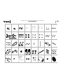
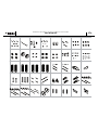
Ersatzteilliste, Spare parts list, Liste des pièces détachées, Pezzi di ricambio
S6068
S7019
S7019
S7019
S7019
S7019
S7019
S7019
S7019
S7019
S6071
(F) S7026
(R) S7027
(F) S7021
(R) S7022
S7032
S7036
S7036
S7035
S7035
S7037
S7037
S7040
M0045
M0041
E2.5
E2.5
E2.5
S7045
M0034
M3X12
M3X12
M0045
M0036
B1050
B1050
M0039
M0039
M0035
M0043
M0037
S7042
S7042
S7042
S6060
S6060
S6060
S6060
S7081
3X12TP
3X12TP
3X12TP
3X12TP
S7034
S7034
M1104
M3X10
M3X10
M3X10
M3X10
M1104
3X12TP
3X12TP
S7044
S7044
S7044
S7044
M0025
M0025
M0022
M0022
M0024
B1510
B1510
M0019
M0026
M0021
M0021
M0086
M0023
M0020
M0038
M1160
M1160
3MM WASHER
M0038
M0038
M0038
M0067
M1162
M1162
M1162
M1162
M1162
M1159
E2.5
S7031
S7033
S7033
M0091
M0091
M0091
M0091
M0091
M0091
M0090
M0088
M1163
M1163
ST SERVO
M
1164
M
1164
M1164
M0038
M1162
2.6X8
3X12TP
3X12TP
M0081
3X12TP
3X12TP
3X12TP
3X12TP
M0094
M
3X20
M0074
3X8TP
3X8TP
3X8TP
M3X10
M3X10
M3X10
3
X10TP FH
3X10TP FH
3X10TP FH
3X10TP FH
3X10TP FH
3X10TP FH
3X10TP FH
3X10TP FH
3X10TP FH
3X10TP FH
3X10TP FH
3X10TP FH
3X10TP FH
3X10TP FH
3X10TP FH
3X10TP FH
3X12TP FH
3X12TP FH
M3X8TP FH
M3X6TP FH
3X8TP
S7083
S7046
M4 NUT
RS540
4818
M3X3
4895
M0082
M0043
M
0043
B0850
B0850
E3.5
E3.5
M0087
M0087
M
0082
E4
S7041
E2.5
E2.5
E2.5
S7035
S7035
S7036
S7036
S7037
S7037
M3NUT
S6060
S6060
S6060
S6060
S7082
3X12TP
3X12TP
3X12TP
3
X12TP
3X12TP
3X12TP
M
3X10
M3X10
M3X10
M3X10
M1104
M1104
S7034
S7034
M3X8FH
M3X10
M0037
M0043
B1050
M0061
M0045
B1050
M0064
S7043
S
7043
S7043
M0036
M
0045
S7045
M3X8FH
M3X18
M3WASHER
M0092
M0048E
M0102
M0102
M0084
M0096
M0096
M0083
BALL DIFF.
3X10TP FH
3X10TP FH
E2
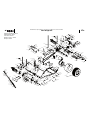
Explosionszeichnung: Chassis
Exploded view: chassis
Vue eclatée: châssis
Disegno esploso : chassis
Despiece: Chasis

Dark Knight EP
17
2036
No.
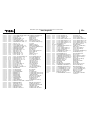
Ersatzteilliste, Spare parts list, Liste des pièces détachées, Pezzi di ricambio
2
0190017
20190018
2
0190019 20190020
20190021
20190022
20190023
20200002
5
X8 METAL BUSHING (3)
20170001
20170002
20170003
20170004
20170005 20170006
20170007
20170008
20170009
20340003
20170012
20170013
20170014
20170016
20210006
20190039
20190040
20190041
20190042
20190043
20190044
20210007 20190045
20190046
20190047
20190048
20190049
20190050
20190065
20190058
20360004 20340002
Schraubenset
Screws bag
Kit de vis
set viti
Juego de tornillos

Dark Knight EP
2036
No.
18
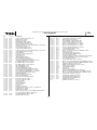
Ersatzteilliste, Spare parts list, Liste des pièces détachées, Pezzi di ricambio
20170027
20210011
20170031
20170033
20210013
20170034
20170086
20170087
20170088 20360011 20170074
20170079
20170082
20280021
20280022
20280023
20280024
20280025
20280026
20280027
20340008
20340009 20340005 20350002
FRONT BUMPER TRUCK
20340010
20350003 20340004
20340011
20340012
20350004
20350005 20360005
20360006 20350006
20350007
20350008
20360007 20360008
20360009 20360010

Dark Knight EP
19
2036
No.
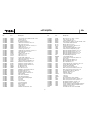
No. POS. No. BEZEICHNUNG DESCRIPTION
20170001 M0034 ACHSSCHENKELHALTER VORNE LI+RE STEERING HUB CARRIER L+R
20170002 M0035 ACHSSCHENKEL 2 ST. STEERING BLOCKS (2)
20170003 M0036 RADACHSEN 4 ST. WHEEL AXLE (4)
20170004 M0037 FELGENMITNEHMER 4 ST. WHEEL HUB (4)
20170005 M0038 KUGELKOPF 4MM 4 ST. 4MM BALL JOINT (4)
20170006 M0039 ACHSCHENKELLAGERUNG 4 ST. FLANGE PIPE ( BLACK) (4)
20170007 M0041 QUERLENKERSTIFT 25MM 2 ST. SUS. ARM PIN 25MM (GOLD) (2)
20170008 M0043 STIFT 2X10 5 ST. 2x10 PIN (5)
20170009 M0045 KUGELKOPF 6MM 6 ST. 6MM BALL JOINT (6)
20170012 M0061 ACHSSCHENKEL HINTEN 2 ST. REAR HUB CARRIER (2)
20170013 M0064 QUERLENKERSTIFT 24MM 2 ST. SUS. ARM PIN 24MM (BLACK) (2)
20170014 M0067 LENKHEBELSCHAFT 4MM 4MM PILOT SHAFT
20170016 M0074 ANTENNENROEHRCHEN ANTENNA PIPE
20170027 M1104 KAROSSERIESPLINTE 8 ST. BODY PINS (8)
20170031 M1160 SERVOSAVER SET 1 SERVO SAVER SUPPORT SET
20170033 M1162 SERVOSAVER SET 2 SERVO SAVER SET
20170034 M1164 LENKGESTAENGE SET TIE ROD SET
20170074 S6060 KUGELKOPF 6MM 4 ST. 6MM BALL STUD (4)
20170079 S6068 STOSSD.-DECKEL 4 ST. SHOCK CAP (4)
20170082 S6071 STOSSD.-DICHTUNGSKAPPE 4 ST. SHOCK DIAPHRAGM SET (4)
20170086 B0850 KUGELLAGER 5X8X2,5 6 ST. 5x8x2,5 BALL BEARING (6)
20170087 B1050 KUGELLAGER 5X10X4 6 ST. 5x10x4 BALL BEARING (6)
20170088 B1510 KUGELLAGER 10X15X4 4 ST. 10x15x4 BALL BEARING (4)
20190017 M0019 DIFF.-ACHSE, LANG DIFF AXLE LONG (1)
20190018 M0020 DIFF.-ACHSE, KURZ DIFF AXLE SHORT (1)
20190019 M0021 DIFF.-SCHEIBE 2 ST. DIFF DRIVE RING (2)
20190020 M0022 DIFF.-DRUCKSCHEIBE 2 ST. THRUST WASHER (2)
20190021 M0023 DIFF.-KUGEL 1/8" 8 ST. 1/8" DIFF BALL (8)
20190022 M0024 DIFF.-KUGEL 1/16" 10 ST. 1/16" THRUST BALL (10)
20190023 M0025 DIFF.-BEFEST.-SCHRAUBE 2 ST. DIFF ADJUSTING SCREW (2)
20190039 M0082 GETRIEBEWELLE SPUR GEAR SHAFT
20190040 M0083 ALU-MOTORPLATTE MOTOR PLATE
20190041 M0084 ALU-SEITENPLATTE SIDE PLATE
20190042 M0085 HAUPTZAHNRADNABE SPUR GEAR HUB
20190043 M0086 RIEMENRAD 32Z 32T TIMING BELT PULLEY SET (2)
20190044 M0087 RIEMENRAD 15Z 15T TIMING BELT PULLEY SET (2)
20190045 M0090 ZENTRALHALTER CENTER BULKHEAD
20190046 M0091 AKKUHALTERSET BATTERY PACK HOLDER SET
20190047 M0092 DISTANZSTANGEN ALUM. JOINT 8X30 MM (3)
20190048 M0094 ANTENNENHALTER ANTENNA PIPE POST
20190049 M0095 SCHRAUBENSET SCREWS BAG EP
20190050 M0096 LAGERSCHEIBEN 5x8 5X8 BEARING HOUSINGS (2)
20190058 RS540 ELEKTROMOTOR M. KABEL + STECKER MOTOR
20190065 M0102 RIEMENSPANNERSET MAIN BELT TENSIONER SET
20200002 M0026 GLEITLAGER 5x8 3 ST. 5X8 METAL BUSHING (3)
20210006 M0081 GFK-RC-PLATTE 2 MM 2MM UPPER DECK BLACK FRP
20210007 M0088 ZAHNRIEMEN VO 201Z DRIVE BELT FRONT
20210011 M1159 LENKSTANGE 36MM STEERING JOINT 36MM
20210013 M1163 LENKSERVO HALTER 2 ST. STEERING SERVO MOUNT X2
No. POS. No. BEZEICHNUNG DESCRIPTION
20280021 S7018 STOSSD.-ZYLINDER 4 ST. SHOCK BODY (4)
20280022 S7019 STOSSD.-TEILESATZ 4 SET SHOCK P
ARTS SET(4)
20280023 S7020 STOSSD.-O-RINGE 4 SET SHOCK O-RINGS SET (4)
20280024 S7021 STOSSD.-FEDER VORNE D1,2 2 ST. SHOCK SPRINGS FRONT D=1.2
20280025 S7022 STOSSD.-FEDER HINTEN D1,2 2 ST. SHOCK SPRINGS REAR D=1.2(2)
20280026 S7023 STOSSD.-FEDER VORNE D1,3 2 ST. SHOCK SPRINGS FRONT D=1.3
20280027 S7024 STOSSD.-FEDER HINTEN D1,3 2 ST. SHOCK SPRINGS REAR D=1.3(2)
20340002 4895 HAUPTZAHNRAD 95Z SPUR GEAR 95T 48 PITCH
20340003 M0048E ZAHNRIEMEN HI DRIVE BELT REAR
20340004 S7035 QUERLENKERHALTER UNTEN 4 ST. LOWER SUS. HOLDER F&R (4)
20340005 S7031 CHASSISPLATTE MAIN CHASSIS
20340008 S7026 STOSSD.-STANGE VORNE 2 ST. SHOCK SHAFT FRONT (2)
20340009 S7027 STOSSD.-STANGE HINTEN 2 ST. SHOCK SHAFT REAR (2)
20340010 S7033 STUETZE D8X30MM 2 ST. 8X30 POST (2)
20340011 S7036 QUERLENKERSTIFT 46MM 2 ST. SUS. ARM PIN 46MM (BLACK) (2)
20340012 S7037 DIFF.-HALTER LI+RE 2 ST. F&R BULKHEAD L+R (2)
20350002 S7032 FRONTRAMMER TRUCK FRONT BUMPER TRUCK
20350003 S7034 KAROSSERIEHALTER TRUCK 4 ST. BODY POST (4)
20350004 S7040 QUERLENKER VORNE UNTEN 2 ST. FRONT LOWER SUS. ARM (2)
20350005 S7041 QUERLENKER HINTEN UNTEN 2 ST. REAR LOWER SUS. ARM (2)
20350006 S7044 LENKGESTAENGE M. TRUCK SET TIE ROD SET
20350007 S7045 ANTRIEBSWELLEN 4 ST. DRIVE SHAFT 6X69 MM (4)
20350008 S7046 FELGEN M. TRUCK 2ST. WHEEL RIM (2)
20360001 S7084P FERTIGKAROSSERIE FINISHED BODYWORK
20360002 S7084 KAROSSERIE BODYWORK
20360003 S7084-1 DEKORBOGEN DECAL SHEET
20360004 4818 ANTRIEBSRITZEL 18Z STANDARD PINION GEAR 18T 48 PITCH
20360005 S7042 QUERLENKER VORNE OBEN 2 ST. FRONT UPPER ARM (2)
20360006 S7043 QUERLENKER HINTEN OBEN 2 ST. REAR UPPER ARM (2)
20360007 S7053 STOSSDAEMPFER KPL. VO 2 STK. F. SHOCK ABSORBER SET (2)
20360008 S7054 STOSSDAEMPFER KPL. HI 2 STK. R. SHOCK ABSORBER SET (2)
20360009 S7081 ALU-STOSSD.-HALTER VORNE FRONT SHOCK TOWER
20360010 S7082 ALU-STOSSD.-HALTER HINTEN REAR SHOCK TOWER
20360011 S7083 REIFEN M. TRUCK 2ST. TYRE W/INSERT (2)
5014 DOPPELKLEBEBAND 3,2X19X1000 DOUBLE-SIDED FOAM TAPE
3,2X19X1000
Ersatzteilliste, Spare parts list, Liste des pièces détachées, Pezzi di ricambio

Dark Knight EP
20
2036
No.
Ersatzteilliste, Spare parts list, Liste des pièces détachées, Pezzi di ricambio
RÉF. POS. NO. DÉSIGNATION
20170001 M0034 PORTE FUSÉE D’ESSIEU AVANT GA + DR
20170002 M0035 FUSÉE D'ESSIEU 2 PIÈCES
20170003 M0036
AXES DE ROUE 4 PIÈCES
20170004 M0037 ENTRAÎNEUR DE JANTE 4 PIÈCES
20170005 M0038 PIVOT SPHÉRIQUE 4 MM 4 PIÈCES
20170006 M0039 PALIER DE FUSÉE D'ESSIEU 4 PIÈCES
20170007 M0041 GOUPILLE DE BRAS D'OSCILLANT TRANSVERSAL 25 MM 2 PIÈCES
20170008 M0043 GOUPILLE 2X10 5 PIÈCES
20170009 M0045 PIVOT SPHÉRIQUE 6 MM 6 PIÈCES
20170012 M0061 FUSÉE D'ESSIEU ARRIÈRE 2 PIÈCES
20170013 M0064 GOUPILLE DE BRAS D'OSCILLANT TRANSVERSAL 24 MM 2 PIÈCES
20170014 M0067 TIGE DE LEVIER DE DIRECTION 4 MM
20170016 M0074 TUBE D'ANTENNE
20170027 M1104 GOUPILLE DE CARROSSERIE 8 PIÈCES
20170031 M1160 SAUVE-SERVO 1 KIT
20170033 M1162 SAUVE-SERVO 2 KIT
20170034 M1164 TRINGLE DE DIRECTION KIT
20170074 S6060 PIVOT SPHÉRIQUE 6 MM 4 PIÈCES
20170079 S6068 CAPUCHON D'AMORTISSEUR 4 PIÈCES
20170082 S6071 CHAPEAU D'ÉTANCHÉITÉ D'AMORTISSEUR 4 PIÈCES
20170086 B0850 ROULEMENT À BILLES 5X8X2,5 6 PIÈCES
20170087 B1050 ROULEMENT À BILLES 5X10X4 6 PIÈCES
20170088 B1510 ROULEMENT À BILLES 10X15X4 4 PIÈCES
20190017 M0019 AXE DE DIFFÉRENTIEL LONG
20190018 M0020 AXE DE DIFFÉRENTIEL COURT
20190019 M0021 DISQUE DE DIFFÉRENTIEL 2 PIÈCES
20190020 M0022 RONDELLE DE BUTÉE DE DIFFÉRENTIEL 2 PIÈCES
20190021 M0023 PIVOT SPHÉRIQUE DE DIFFÉRENTIEL 1/8" 8 PIÈCES
20190022 M0024 PIVOT SPHÉRIQUE DE DIFFÉRENTIEL 1/16" 10 PIÈCES
20190023 M0025 VIS DE FIXATION DE DIFFÉRENTIEL 2 PIÈCES
20190039 M0082 ARBRE D'ENGRENAGE
20190040 M0083 PLAQUE SUPPORT-MOTEUR EN ALU
20190041 M0084 PLAQUE LATÉRALE EN ALU
20190042 M0085 MOYEU DE ROUE DENTÉE PRINCIPALE
20190043 M0086 POULIE DE COURROIE 32 DENTS
20190044 M0087 POULIE DE COURROIE 15 DENTS
20190045 M0090 SUPPORT CENTRAL
20190046 M0091 KIT PORTE-ACCU
20190047 M0092 TIGES D'ÉCARTEMENT
20190048 M0094 PORTE-ANTENNE
20190049 M0095 KIT DE VIS
20190050 M0096 RONDELLE D'APPUI 5X8
20190058 RS540 MOTEUR ÉLECTRIQUE AVEC CORDON + CONNECTEUR
20190065 M0102 KIT TENDEUR DE COURROIE
20200002 M0026 PALIER LISSE 5X8 3 PIÈCES
20210006 M0081 PLAQUE DE MISE EN PLACE DE L'ENSEMBLE DE RÉCEPTION EN
PLASTIQUE RENFORCÉ FIBRE DE VERRE 2 MM
20210007 M0088 COURROIE CRANTÉE AVANT 201 DENTS
20210011 M1159 BARRE DE DIRECTION 36 MM
RÉF. POS. NO. DÉSIGNATION
20210013 M1163 SUPPORT-SERVO DE DIRECTION 2 PIÈCES
20280021 S7018 VÉRIN D'AMORTISSEUR 4 PIÈCES
20280022 S7019 PETITS ÉLÉMENTS D'AMORTISSEUR 4 KITS
20280023 S7020 JOINTS TORIQUES D'AMORTISSEUR 4 KITS
20280024 S7021 RESSORT D'AMORTISSEUR AV. D1,2 2 PIÈCES
20280025 S7022 RESSORT D'AMORTISSEUR ARR. D1,2 2 PIÈCES
20280026 S7023 RESSORT D'AMORTISSEUR AV. D1,3 2 PIÈCES
20280027 S7024 RESSORT D'AMORTISSEUR ARR. D1,3 2 PIÈCES
20340002 4895 COUE DENTÉE PRINCIPALE 95 DENTS
20340003 M0048E COURROIE CRANTÉE ARR.
20340004 S7035 BRAS D'OSCILLATION TRANSVERSAL INFÉRIEUR 4 PIÈCES
20340005 S7031 PLAQUE DE CHÂSSIS
20340008 S7026 TIGE D'AMORTISSEUR AVANT 2 PIÈCES
20340009 S7027 TIGE D'AMORTISSEUR ARRIÈRE 2 PIÈCES
20340010 S7033 SUPPORT D8X30MM 2 PIÈCES
20340011 S7036 GOUPILLE DE BRAS D'OSCILLANT TRANSVERSAL 46 MM 2 PIÈCES
20340012 S7037 SUPPORT DE DIFFÉRENTIEL GAUCHE + DROITE 2 PIÈCES
20350002 S7032 BOUCLIER AVANT M. TRUCK
20350003 S7034 PORTE-CARROSSERIE M. TRUCK 4 PIÈCES
20350004 S7040 BRAS D'OSCILLATION TRANSVERSAL AVANT INFÉRIEUR 2 PIÈCES
20350005 S7041 BRAS D'OSCILLATION TRANSVERSAL ARRIÈRE INFÉRIEUR 2 PIÈCES
20350006 S7044 TRINGLE DE DIRECTION M. TRUCK 1 KIT
20350007 S7045 ARBRES DE TRANSMISSION M. TRUCK 4 PIÈCES
20350008 S7046 JANTES M. TRUCK 2 PIÈCES
20360001 S7084P CARROSSERIE TERMINÉE
20360002 S7084 CAROSSERIE
20360003 S7084-1 FEUILLET D’AUTOCOLLANTS
20360004 4818 PIGNON D’ENTRAINEMENT 18 DENTS STANDARD
20360005 S7042 BRAS D'OSCILLATION TRANSVERSAL AV. SUPÉRIEUR 2 PIÈCES
20360006 S7043 BRAS D'OSCILLATION TRANSVERSAL ARR. SUPÉRIEUR 2 PIÈCES
20360007 S7053 AMORTISSEUR COMPLET AV. 2 PIÈCES
20360008 S7054 AMORTISSEUR COMPLET ARR. 2 PIÈCES
20360009 S7081 PORTE-AMORTISSEUR AVANT EN ALU
20360010 S7082 PORTE-AMORTISSEUR ARRIÈRE EN ALU
20360011 S7083 PNEUMATIQUES 2 PIÈCES
5014 ADHÉSIVE DOUBLE FACE 3,2X19X1000
La pagina si sta caricando...
La pagina si sta caricando...
La pagina si sta caricando...
La pagina si sta caricando...
La pagina si sta caricando...
La pagina si sta caricando...
La pagina si sta caricando...
La pagina si sta caricando...
-
 1
1
-
 2
2
-
 3
3
-
 4
4
-
 5
5
-
 6
6
-
 7
7
-
 8
8
-
 9
9
-
 10
10
-
 11
11
-
 12
12
-
 13
13
-
 14
14
-
 15
15
-
 16
16
-
 17
17
-
 18
18
-
 19
19
-
 20
20
-
 21
21
-
 22
22
-
 23
23
-
 24
24
-
 25
25
-
 26
26
-
 27
27
-
 28
28


ROBBE Dark Knight EP 2036 Operating Instructions Manual
- Categoria
- Giocattoli telecomandati
- Tipo
- Operating Instructions Manual
in altre lingue
- English: ROBBE Dark Knight EP 2036
- français: ROBBE Dark Knight EP 2036
- español: ROBBE Dark Knight EP 2036
- Deutsch: ROBBE Dark Knight EP 2036
Documenti correlati
Altri documenti
-
Castorama Novah Guida utente
-
-
Kyosho MBW023@Universal Swing Shaft Manuale utente
-
-
Tamiya TA07 R Manuale del proprietario
-
ECX ECX03433 Manuale del proprietario
-
Losi LOS03041 Manuale del proprietario
-
-
 Little Tikes Cozy Coupe® Off-Roader Manuale del proprietario
-
Rev-A-Shelf 3472-32-11-52 Instruction Sheet
