
RTX
C78
L19
L18
Rl4 a
C56
C57
C58
L22
R29
Tr18
R32
C73
C75
C74
L16
C59
C60
D17D16C72
R26
R30
C54 C55
R28
L17
Tr17
D20
C61
C62
C63
C64
C77
C76
R31
Tr13
L14
L13
L15
C45
C46
C47
C50
D11
D12
C48
C49
R18
Tr10
R17
C51
C7
C2
C4
L1
C6
C1
C3
L2
Rl2
C10
D1
C8
C5
D2
C9
Tr3
R3
R2
Tr1
R1
C11
R4
Rl2
Rl3
C91
Rl4
R23
R22
8
13
14
R21
S2
C52
D15
R20
R19
D13
Tr13
Tr13
R25
R24
D14
S3
Tr19
R33
R34
D23
Tr14
C89
R36
R37
D25
Tr16
Tr15
R39
R40
R38
D26
C53
Rl1
3,4,5,6,7,9,11
R8
C12
R6
Tr2
R5
R7
S1
12
10
Ic1
C92
R45
Tr6
Tr5
R44
R42
R41
R43
Tr7
D27
D28
D24
R35
C88
C90
C80
L21
C70
C71
L20
C69
R27
C79
L23
C65
C66
D18
D19
C68
C67
Rl4 b
R46
C39
C42
C44
Scr
R48
C95C96
L26
L25
L24
C94
C87
Fuse
D21
D22C86
C38
C43
C40
IN Vdc +
C84C85
C41
R47
C81
C82
C83
C93
Rl3
L11
L12
R50
C101
L27
L28
D29
R49
D31
C100
D32
D30
C98
C99
C97
ANT
C23
C35
L5
Rl1 a
C16
C18
C19
C17
C31
R12
C30
D5
L3
C13
D3
D4
R9
Tr4
C22
D8
C20
C21
L4
Tr8
L6
R10
C14
C15
C32
D6
D7
R16
C34
C33
R15
Tr9
L9
R14
R13
L8
C26
L7
C25
R11
C24
C27 C28
C29
Rl1 b
C37
L10
C36
D9 D10
R51
R52
R55
R53
R54
Ic2
C102
C103
C104
C105
C106
C107
C108 C109
D34
D35
D36
D37
D38
D33
http://www.rmitaly.com
Red TX
Green RX
V-ULA 50V-ULA 50
OUTPUT POWER
Dualband Linear Amplifier
Warning
FM
1
Protection
VHF
SSB
Simplex
OFF
UHF
Duplex
ON
ON
AMPLIFICATORE LINEARE BIBANDA
DUAL BAND LINEAR AMPLIFIER
AMPLIFICATEUR LINEAIRE BIBANDE V/UHF
VHF/UHF LINEARVERSTÄRKER DUO-BAND
AMPLIFICADORES LINEAL BIBANDA VHF/UHF
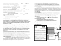
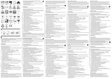
Mod. V-ULA 50
Interruttore ON OFF lineare - Amplifier ON OFF switch - Interrupteur ON OFF
- Schalter EIN-AUS für Linearverstärker- Interruptor ON OFF del amplificador
Interruttore selezione modo Simplex o Duplex - Switch to select simplex or
duplex mode - Interruptor Simplex/Cross-bande - Schalter für Simplex oder
Duplex - Interruptor de selección de Simplex o Duplex
Interruttore SSB FM - SSB FM switch - Interrupteur FM/SSB CW -
Betriebsartenschalter SSB FM - Interruptor SSB FM
Indicatore potenza d'uscita - output power meter - Indicateur de puissance de
sortie - Ausgangs leistung-anzeige -Indicador de potencia de salida
Led indicatore di accensione lineare - Amplifier switching on led indicator - Led
temoin de mise sous tension - Verstärker LED Anzeige - Led indicador de
encendido del amplificador.
Led indicatore di stato amplificatore UHF (Rosso TX Verde RX) - LED
indicating UHF amplifier status (red TX, green RX) - LED temoin de bande UHF
(rouge TX, vert RX) - LED-anzeige für UHF-frequenz (rot = TX grün = RX) -
Led indicador de la posición del amplificador UHF (Rojo TX - Verde RX)
Led indicatore di stato amplificatore VHF (Rosso TX Verde RX) - LED
indicating VHF amplifier status (red TX, green RX) - LED temoin de bande VHF
(rouge TX, vert RX) - LED-anzeige für VHF-frequenz (rot = TX grün = RX) -
Led indicador de la posición del amplificador VHF (Rojo TX - Verde RX)
Indicatore di stato di protezione - Protection state indicator - LED temoin de
mise en service de la protection - Überlastungschutz LED - Indicador de protec
ción
E
E
E
G
G

VHF UHF
Frequenza - Frequency - Fréquence - Frequenz - Frecuencia 144 - 148 / 430 - 440 MHz
Alimentazione - Supply - Alimentation - Versorgungsspannung -
Alimentación 12 - 14 Volt cc
Assorbimento - Input energy - Courant - Stromaufnahme - Consumo 3 - 10 Amp
Potenza d'ingresso - Input power - Puissance d'entrée - Ansteuerung -
Potencia de entrada 0,5 - 8W
Potenza d'uscita - Output power - Puissance de sortie -
Ausgangsleistung -Potencia de salida 70 W / 50 W Max
ROS ingrsso - Input SWR - TOS d'entrée -SWR Betrieb bis -ROE de entrada 1.1 - 1.5
Funzionamento - Mode - Functionnement - Funktionen - Modos de emisión FM SSB
Preamplificatore - Preamplifier - Préamplificateur -
Empfangsverstärker kann - Preamplificador 18 - 22 / 10 - 18 dB
fusibile - Fuse - Fusible - Sicherung - Fusible 2 x 5A
ICommutazione elettronica.
Protezione contro l'inversione di polarità.
Protezione contro ROS eccessivo.
CONSIGLI D'USO
Per un corretto uso dell'amplificatore V-ULA 50 si consiglia di posizio-
narlo in modo che sia assicurato un sufficiente flusso di aria al radiatore di
calore, utilizzare cavi di alimentazione il più corti possibile e comunque non più
lunghi di 3 m., possibilmente collegati direttamente alla batteria e di sezione
non inferiore a 2,5 mm².
Il cavo di discesa a 50 Ω, deve essere di buona qualità, adeguato alla frequenza
ed alla potenza di lavoro e di lunghezza minima necessaria in quanto introduce
una sensibile attenuazione in trasmissione con perdita di potenza e soprattutto in
ricezione peggiorando il rapporto segnale-rumore, utilizzare un'antenna che
accetti largamente la potenza dellamplificatore, e che abbia ROS non superiore
a 1.5 alla massima potenza, i connettori devono essere di alta qualità in teflon.
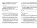
Il collegamento tra RTX e Lineare deve essere effettuato con cavo a 50 Ω,
lungo 70 cm.
Non rimanere in trasmissione per lungo tempo senza intervalli ragionevoli per
permettere il raffreddamento dei transistors. In caso di utilizzo in stazione base
si consiglia l'utilizzo di una batteria con caricabatteria in tampone .
Laccensione del LED indica lintervento della protezione per livello eccessi-
vo di onde stazionarie (ROS), per il ripristino della funzionalità del lineare
spegnere e riaccendere linterruttore dopo aver eliminato il motivo di inter-
vento della protezione.
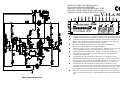
Lamplificatore V-ULA 50 è un amplificatore bibanda 2m. e 70 cm. FULL-
DUPLEX ed è dotato di due distinti circuiti composti da un amplificatore e
preamplificatore accoppiati con opportuni duplexer circolari
el motivo que provoco el funcionamiento de circuito de protección.
El amplificador V-ULA 50 es un bibanda para 2m y 70 cm. FULL
Duplex, y dotado de dos circuitos distintos, compuestos de amplificador y
preamplificador acoplados con su correspondientes duplexores circulares.
Posición SIMPLEX
El amplificador reconoce automáticamente la banda que se utiliza, y se
posiciona en ella ya sea en recepción o transmisión, comportándose como un
amplificador normal «habla-escucha». In trasmisión, se indica la banda utiliza-
da por medio de la conmutación de verde a rojo de uno de los LED para este
efecto ( ó ).
Posición DUPLEX
El amplificador, se posiciona automáticamente en transmisión en la
banda en que transmite el transceptor, y en recepción, en la banda opuesta,
Antenna
RTX
ANT
Rosso - Red
Nero - Black
70 cm
Batt. 12 V
+
-
RTX Max 8 W
operando así en FULL DUPLEX. La condición en que trabaja, viene
indicada por los colores de los dos LED y , rojo para TX y
verde para RX.
La luz verde de los dos LED y , indica el funcionamiento
del preamplificador de antena.
Garantía de 24 meses desde la fecha de la factura..
Recordamos que el uso de los amplificadores lineales esta
regulado por leyes especificas. La firma constructora declina cual-
quier responsabilidad derivada de un uso incorrecto.
La no observancia de las instrucciones descritas, anula la
garantía que en ningún caso cubre los transistores finales y las
partes decorativas.
This is to certify that:
The linear amplifier Mod V-ULA 50
complies with the provisions of the Directive of
the Council of the European Communities on
the approximation of the laws of the Member
States relating to electromagnetic compatibility
(EMC Directive 89/336/EEC).
This declaration of conformity of European
Communities is the result of an examination
carried out by the Quality Assurance Depart-
ment of
RM Costruzioni elettroniche
in accordance with European
Telecommunicatons Standards ETS 300 684 -
300 339, of December 1995.
ITALY
EC Certificate of conformity
(to EMC Directive 89/336/EEC)
2
1

Posizione SIMPLEX:
Lamplificatore riconosce automaticamente la banda utilizzata e si posizio-
na in essa sia in ricezione che in trasmissione e quindi si comporta come un normale
amplificatore parla-ascolta. In trasmissione la banda utilizzata viene evidenziata
tramite le commutazione da verde a rosso di uno dei due Led preposti ( e ).
Posizione DUPLEX
Lamplificatore si posiziona automaticamente in trasmissione nella banda
comandata dal ricetrasmettitore ed in ricezione nella banda opposta operando
quindi in FULL-DUPLEX, la condizione è evidenziata dal colore dei due Led 6
e 7 (rosso TX - verde RX).
La luce verde dei due Led e indica il funzionamento del preamplificatore
dantenna
Garanzia mesi 24 dalla data dello scontrino o ricevuta.
Si ricorda che l'utilizzo degli amplificatori lineari è regolato da leggi
specifiche e quindi se ne consiglia la visione prima dell'utilizzo e comunque la ditta
costruttrice declina ogni responsabilità derivata da un non corretto uso rispetto le
norme vigenti.
La non osservanza delle istruzioni sopra scritte annulla ogni forma di
garanzia che comunque non include i transistors finali e le parti estetiche.
GElectronic switch.
Inversion polarity protection.
Protection against excessive SWR.
Suggestion of use
For the correct use of the AMPLIFIER V-ULA 50 it is advised to posi-
tion it in such a way to assure a sufficient flow of air to the heat-radiator. Use
as short as possible feeding cables, however not longer than 3 meters, directly
connected to the battery with a section of 2,5 mm² minimum
The descend cable 50 Ω has to be of good quality, suitable to the fre-
quency and to the power of job and with the minimum required length as it in-
troduces a sensitive attenuation in transmission with loss of power and espe-
cially in receipt worsening the relationship signal-noise.
Use a spar largely accepting the power of AMPLIFIER and having
SWR not exceeding 1.5 at the max power. Use high quality Teflon connectors.
The connection between RTX and AMPLIFIER has to be effected with
50 Ω cable 70 cm. long.
Do not remain in transmission for long time without reasonable inter-
vals to allow the cooling of the transistors. In case of use in basic station it is
recommended the use of a battery with battery charge in buffer.
The lighting of led indicates the intervention of protection for exces-
sive level of SWR, to restore the functionality of the AMPLIFIER switch
Machen sie keine zu langen Durchgänge, um den Verstärker nicht zu
erhitzen ! Bei max. Leistung Stationärbeitreb achten Sie bitte darauf, daß ein
stabilisiertes Netzteil mit ausreichender Stromstärke benutzt wird!
LED () zeigt ein schlechtes SWR an, TX ist sofort zu unterbrechen.
Position: SIMPLEX
Der Verstärker erkennt und arbeitet automatisch in dem von Ihnen
gewählten Frequenzbereich.
Position: DUPLEX
der Verstärker wechselt automatisch in das von Ihnen gewünschte Band
und erkennt den Empfänger automatisch.
Die grüne LED zeigt an, das Empfangssignal ebenfalls Verstärkt wird.
Nach dem Kauf wird eine Garantie von 24 Monaten gewährt. Auf
Endstufe und andere Halbleiter wird keine Garantie gewährt !!!
Achten Sie darauf, dass der Verstärker nur von Befugten in Betrieb
genommen werden darf. Bei Nichtbeachtung droht Geld-oder Haftstrafe.
EConmutación electrónica.
Protección contra la inversión de polaridad.
Protección contra una R.O.E. excesiva
CONSEJOS PARA SU USO
Para un correcto uso del amplificador V-ULA 50, es aconsejable situarlo
de manera que quede asegurado un suficiente flujo de aire hacia el radiador de
calor, utilizar asimismo un cable de alimentación lo más corto posible, en
ningún caso mayor de 3 m., y a ser posible, conectado directamente a la batería,
con una sección no inferior a 1,5 mm².
La bajada de antena de 50 Ω, debe ser de buena calidad, adecuado a la
frecuencia y potencia de trabajo. Dicho cable, deberá tener el mínimo largo
necesario para evitar la sensible atenuación y la consiguiente pérdida de poten-
cia, y sobre todo en recepción al empeorar la relación señal-ruido. Utilizar
también una antena que permita ampliamente la potencia del amplificador, con
una R.O.E. no superior a 1/1,5 en la máxima potencia. Los conectores deberán
ser de alta calidad, a ser posible en teflón.
En enlace entre el transceptor y el lineal, debe ser efectuado con cable de
50 Ω, de una medida de 70 cm.
No permanecer en transmisión mucho tiempo sin un espacio razonable
que permita el enfriamiento de los transistores. En caso de uso en estación base
se aconseja usar una batería con carga permanente.
En encendido del LED , indica el funcionamiento de protección por un
excesivo nivel de R.O.E.. Para reiniciar la operación y el funcionamiento del
amplificador, apagar y encender el interruptor , después de haber eliminado

OFF and ON after eliminating the reason calling for protection.
V-ULA 50 amplifier, is a 2 m. 70 cm. full duplex dual band amplifier,
provided with two distinct circuits compost of amplifier and preamplifier cou-
pled by means of proper round duplexers.
Position SIMPLEX.
The amplifier automatically recognized the used band and set itself on
it either in reception and in transmission, so it acts as regular Speak-listen am-
plifier. When transmitting the band is evidenced by the commute green to red of
one of the two apposite leds.
Position DUPLEX.
The amplifier automatically sets itself in transmission in the band re-
quired by ricetranceiver and in reception in the opposite band, so that working
in full duplex; This status is evidence by the colour of the two leds and
red TX and green RX.
The green light indicate the operating status of the antenna preamplifier.
24 months warranty from date of receipt.
Please note that the use of LINEAR AMPLIFIER is ruled by specific
laws, that are to be known by the user, anyway the manufacturer declines any
responsibility coming from an uncorrected use.
Any warranty is cancelled if the above instructions are not ob-
served. Final transistor and esthetical parts are not included in the war-
ranty.
FCommutation électronique.
Protéction contre les inversion de polarité.
Protection contre le ROS excessif.
Conseils dinstallation :
Pour fonctionner correctement, votre amplificateur V-ULA 50 doit
impérativement être installé dans un endroit sec et aéré de manière à ce que la
chaleur dégagée par le radiateur soit librement évacuée. Les fils dalimentation
doivent avoir un diamètre dau-moins 2,5 mm² et être le plus court possible (ne
pas excéder 3 m).
Les câbles coaxiaux (50 ohms) utilisés doivent être de bonne qualité et
capable de véhiculer la puissance délivrée par le V-ULA 50. Leur longueur ne
doit par être excessive afin de ne pas induire datténuations tant dans la puis-
sance émise que dans les signaux reçus. Des connecteurs type Téflon sont
recommandés.
Le ROS ne doit pas excédé 1:1,5 lorsque lamplificateur
délivre sa puissance maximale.
La longueur de câble préconisée entre lémetteur-récepteur et lamplifi-
cateur est d'environ 70 cm.
Pour une utilisation en fixe, il est vivement recommandé dutiliser une
alimentation très performante et capable de délivrer lampérage nécessaire pour
un fonctionnement correct du V-ULA 50.
Les périodes démission ne doivent pas être trop prolongée afin que les
transistors de puissance refroidissent normalement.
En cas de ROS anormalement élevé, la protection du V-ULA 50
entrera en action. Lamplificateur doit être éteint puis remis sous tension
pour la déverrouiller.
Le V-ULA 50 est un amplificateur 2 m. et 70 cm. Il sagit dun amplifi-
cateur double bande «full duplex», construit avec deux circuits distincts com-
posés dun amplificateur et dun préamplificateur de réception couplés par un
système de duplexeurs.
Position SIMPLEX
Lamplificateur reconnaît automatiquement la bande utilisée et bascule
directement en émission ou en réception selon si vous parlez ou écoutez.
Quand vous transmettez une Led rouge ou verte sallume correspondant à la
bande utilisée.
Position DUPLEX
Lamplificateur bascule automatiquement en émission sur la bande
utilisée et en réception sur la bande opposée pour travailler en «full duplex».
Cette situation est mise en évidence par la couleur des Led et (rouge pour
TX ou verte pour RX).
Lorsque la Led verte est allumée cela indique le fonctionnement du
préamplificateur dantenne
La période de garanti est de 24 mois, les transistors de puissance ne sont
pas couverts par celle-ci.
DElektronischer Schalter.
Polaritätenschutz.
Schutz gegen übermäßiges SWR (Antennenanpassung)
SICHERHEITS-HINWEISE
Für den Betrieb des Verstärkers V-ULA 50 sollte ein gut durchlüfteter
Platz zur Montage gesucht werden. Möglichst nicht in der Nähe von Heizungs-
ausgängen betreiben! Für die Stromzuführung nur ein Kabel mit 2,5 mm
Durchmesser (Plus und Minus) benutzen, das nicht länger als 3 m ist.
Das verwendete Kabel (50 OHM) sollte möglichst geringe Dämpfung
haben, um TX + RX nicht zu verringern!
Benutzen Sie nur Verbindungsstecker mit Teflon-Isolator. Die Stecker
sollten für die Frequenz des Verstärkers möglichst verlustarm gewählt werden.
Achten Sie darauf, dass das SWR unter 1:1,5 ist. Notfalls justieren Sie Ihre
verwendete Antenne, um die maximale Leistung abstrahlen zu können.

di Marchioni Davide & Daniele s.n.c.
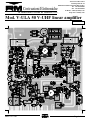
Mod. V-ULA 50 V-UHF linear amplifier
Via IV Novembre 215/5
Casella postale N° 33
40045 Ponte della Venturina (BO) ITALY
Tel +39 0534 60460
Fax +39 0534 60463
E-MAIL [email protected]
http://www.rmitaly.com
Costruzioni Elettroniche
Version 1.01
date 03-01-2002 Page 1 di 6

Mod V-ULA 50 1.01
date 03-01-2002 Page 2 di 6
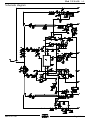
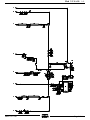
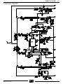
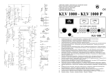
Schematic diagram

Mod V-ULA 50 1.01
date 03-01-2002 Page 3 di 6

Mod V-ULA 50 1.01
date 03-01-2002 Page 4 di 6
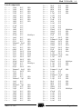
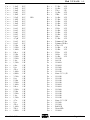
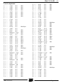
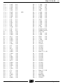
List of components
C 1 = 3,9 pF 50 V NP0
C 2 = 3,9 pF 50 V NP0
C 3 = 2,2 pF 50 V NP0
C 4 = 2,2 pF 50 V NP0
C 5 = 1,8 pF 50 V NP0
C 6 = 3,9 pF 50 V NP0
C 7 = 3,9 pF 50 V NP0
C 8 = 1,8 pF 50 V NP0
C 9 = 1,0 nF 50 V
C 10 = 4,7 µF 16 V
C 11 = 33 µF 16 V
C 12 = 1,0 nF 50 V
C 13 = 1,0 nF 50 V
C 14 = 1,0 nF 50 V
C 15 = 220 nF 63 V Multilayer
C 16 = 1,0 nF 50 V
C 17 = 47 pF 50 V NP0
C 18 = 47 pF 50 V NP0
C 19 = Trimmer 5 - 20 pF NP0
C 20 = 10 pF 50 V NP0
C 21 = 10 pF 50 V NP0
C 22 = 6,8 pF 50 V NP0
C 23 = 33 pF 300 V Mica
C 24 = 33 pF 300 V Mica
C 25 = 33 pF 300 V Mica
C 26 = 12 pF 500 V NP0
C 27 = 15 pF 500 V NP0
C 28 = 100 pF 500 V NP0
C 29 = 220 nF 63 V Multilayer
C 30 = 1,0 nF 50 V
C 31 = 8,2 pF 500 V NP0
C 32 = Trimmer 3 - 10 pF NP0
C 33 = 47 pF 500 V NP0
C 34 = 1,0 nF 50 V
C 35 = 1,0 nF 50 V
C 36 = 2,2 pF 50 V NP0
C 37 = Trimmer 2 - 5 pF NP0
C 38 = 1,0 nF 50 V
C 39 = 1,0 nF 50 V
C 40 = Trimmer 2 - 5 pF NP0
C 41 = 2,2 pF 50 V NP0
C 42 = 3,9 pF 50 V NP0
C 43 = 3,9 pF 50 V NP0
C 44 = 1,8 pF 50 V NP0
C 45 = 2,2 pF 50 V NP0
C 46 = 2,2 pF 50 V NP0
C 47 = 3,9 pF 50 V NP0
C 48 = 3,9 pF 50 V NP0
C 49 = 18 pF 50 V NP0
C 50 = 18 pF 50 V NP0
C 51 = 18 pF 50 V NP0
C 52 = 22 pF 50 V NP0
C 53 = 2,2 pF 50 V NP0
C 54 = 1,0 nF 50 V
C 55 = 4,7 µF 25 V
C 56 = 33 µF 25 V
C 57 = 10 nF 50 V
C 58 = 1,0 nF 50 V
C 59 = 1,0 nF 50 V
C 60 = 1,0 nF 50 V
C 61 = 220 nF 63 V Multilayer
C 62 = 100 pF 50 V NP0
C 63 = 100 pF 50 V NP0
C 64 = 22 pF 50 V NP0
C 65 = 56 pF 500 V NP0
C 66 = Trimmer 5 - 20 pF NP0
C 67 = 100 pF 500 V NP0
C 68 = 100 pF 500 V NP0
C 69 = 390 pF 500 V Mica
C 70 = 390 pF 500 V Mica
C 71 = 22 pF 500 V NP0
C 72 = 100 pF 500 V Mica
C 73 = 2,2 nF 500 V
C 74 = Trimmer 5 - 20 pF NP0
C 75 = 2,2 nF 500 V
C 76 = 1,0 nF 50 V
C 77 = 220 nF 63 V Multilayer
C 78 = 4,7 pF 50 V NP0
C 79 = 4,7 pF 50 V NP0
C 80 = 1,0 nF 50 V
C 81 = Trimmer 3 - 10 pF NP0
C 82 = 1,0 nF 50 V
C 83 = 1,0 nF 50 V
C 84 = Trimmer 3 - 10 pF NP0
C 85 = 3,9 pF 50 V NP0
C 86 = 3,9 pF 50 V NP0
C 87 = 18 pF 50 V NP0
C 88 = 18 pF 50 V NP0
C 89 = 18 pF 50 V NP0
C 90 = 100 nF 50 V
C 91 = 220 nF 63 V Multilayer
C 92 = 470 µF 25V
C 93 = 1,0 nF 50 V
C 94 = 1,0 nF 50 V
C 95 = 1,0 nF 50 V
C 96 = 1,0 nF 50 V
C 97 = 1,0 nF 50 V

C 98 = 1,0 nF 50 V
C 99 = 1,0 nF 50 V
C 100 = 1,0 nF 50 V
C 101 = 10 µF 25 V
C 102 = 1,0 nF 50 V
C 103 = 2,2 pF 50 V NP0
C 104 = 1,0 nF 50 V
C 105 = 1,0 nF 50 V
C 106 = 1,0 nF 50 V
C 107 = 10 nF 50 V
C 108 = 10 nF 50 V
C 109 = 10 nF 50 V
C 110 = 10 µF 25 V
C 111 = 10 nF 50 V
C 112 = 10 nF 50 V
C 113 = 4,7 µF 25 V
C 114 = 10 nF 50 V
C 115 = 10 nF 50 V
R 1 = 12 KΩ ¼ W
R 2 = 2,2 KΩ ¼ W
R 3 = 1,0 KΩ ¼ W
R 4 = 100 Ω ¼ W
R 5 = 12 KΩ ¼ W
R 6 = 2,2 KΩ ¼ W
R 7 = 2,2 KΩ ¼ W
R 8 = 1,0 Ω ½ W
R 9 = 1,2 KΩ ¼ W
R 10 = 6,8 Ω ¼ W
R 11 = 10 Ω ¼ W
R 12 = 470 Ω ¼ W
R 13 = 1,0 KΩ ¼ W
R 14 = 6,8 KΩ ¼ W
R 15 = 3,3 KΩ ¼ W
R 16 = 10 Ω ¼ W
R 17 = 12 KΩ ¼ W
R 18 = 2,2 KΩ ¼ W
R 19 = 1,0 KΩ ¼ W
R 20 = 100 Ω ¼ W
R 21 = 2,2 KΩ ¼ W
R 22 = 12 KΩ ¼ W
R 23 = 2,2 KΩ ¼ W
R 24 = 1,0 Ω ½ W
R 25 = 1,2 KΩ ¼ W
R 26 = 4,7 Ω ¼ W
R 27 = 10 Ω ¼ W
R 28 = 470 Ω ¼ W
R 29 = 1,0 KΩ ¼ W
R 30 = 220 Ω ¼ W
R 31 = 6,8 KΩ ¼ W
R 32 = 3,3 KΩ ¼ W
R
33 = 1,0 KΩ ¼ W
R 34 = 330 Ω 2 W
R 35 = 1,0 KΩ ¼ W
R 36 = 12KΩ ¼ W
R 37 = 1,0 KΩ ¼ W
R
38 = 2,2 KΩ ¼ W
R 39 = 1,0 KΩ ¼ W
R 40 = 1,0 KΩ ¼ W
R 41 = 2,2 KΩ ¼ W
R 42 = 12 KΩ ¼ W
R
43 = 1,0 KΩ ¼ W
R 44 = 1,0 KΩ ¼ W
R 45 = 1,0 KΩ ¼ W
R 46 = 100 Ω ¼ W
R 47 = 2,2 KΩ ¼ W
R
48 = Trimmer 4,7 KΩ
R 49 = Trimmer 220 KΩ
R 50 = 470 Ω¼ W
R 51 = 1,0 KΩ ¼ W
R 52 = 1,0 KΩ ¼ W
R 53 = 22 KΩ ¼ W
R 54 = 10 KΩ ¼ W
R 55 = 1,0 KΩ ¼ W
D 1 = 1N 4148
D 2 = OA 118
D 3 = 1N 4004
D 4 = 1N 4004
D 5 = 1N 5400
D 6 = 1N 4148
D 7 = 1N 4148
D 8 = Zener 5,1 V ½ W
D 9 = 1N 4148
D 10 = 1N 4148
D 11 = 1N 4148
D 12 = 1N 4148
D 13 = 1N 4004
D 14 = 1N 4004
D 15 = 1N 5400
D 16 = 1N 4148
D 17 = 1N 4148
D 18 = 1N 4148
D 19 = 1N 4148
D 20 = Zener 5,1 V ½W
D 21 = 1N 5400
D 22 = 1N 5400
D 23 = Red LED
D 24 = Green LED
D 25 = 1N 4004
Mod V-ULA 50 1.01
date 03-01-2002 Page 5 di 6

D 26 = Bicolor LED
D 27 = 1N 4004
D 28 = Bicolor LED
D 29 = 1N 4148
D 30 = 1N 4148
D 31 = 1N 4148
D 32 = Green LED
D 33 = Green LED
D 34 = Green LED
D 35 = Green LED
D 36 = Green LED
D 37 = Green LED
D 38 = Green LED
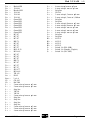
Tr 1 = BC 547
Tr 2 = BC 327
Tr 3 = BC 547
Tr 4 = BD 179
Tr 5 = BC 547
Tr 6 = BC 337
Tr 7 = BC 557
Tr 8 = BLU 45/12
Tr 9 = BF 966 S
Tr 10 = BC 547
Tr 11 = BC 547
Tr 12 = BC 327
Tr 13 = BD 179
Tr 14 = BC 547
Tr 15 = BC 557
Tr 16 = BC 337
Tr 17 = SD 1477
Tr 18 = BF 966 S
Tr 19 = TIP 142
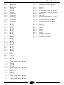
Scr = P0102
Fuse = 2 x 6 A
IC 1 = CD 4013
IC 2 = KA 2288
L 1 = 2 turns wire φ 1 mm on φ 3 mm
L 2 = 2 turns wire φ 1 mm on φ 3 mm
L 3 = Strip line
L 4 = VK 200
L 5 = VK 200
L 6 = 2 turns wire φ 1 mm on φ 6 mm
L 7 = Strip line
L 8 = Strip line
L 9 = Strip line
L 10 = Strip line
L 11 = 2 turns wire φ 1 mm on φ 3 mm
L 12 = 2 turns wire φ 1 mm on φ 3 mm
L 13 = 4 turns wire φ 1 mm on φ 5 mm
L 14 = 4 turns wire φ 1 mm on φ 5 mm
L 15 = 4 turns wire φ 1 mm on φ 5 mm
L 16 = Strip line
L 17 = VK 200
L 18 = 3 turns wire φ 1,5 mm on φ 8 mm
L 19 = 2 turns wire φ 1,3 mm on ½ Balum
L 20 = Strip line
L 21 = Strip line
L 22 = 4 turns wire φ 0,8 mm on φ 5 mm
L 23 = 4 turns wire φ 0,8 mm on φ 5 mm
L 24 = 4 turns wire φ 1 mm on φ 5 mm
L 25 = 4 turns wire φ 1 mm on φ 5 mm
L 26 = 4 turns wire φ 1 mm on φ 5 mm
L 27 = Strip line
L 28 = Strip line
Rl 1 = 4052-12
Rl 2 = 4052-12
Rl 3 = 4052-12
Rl 4 = 4052-12
S 1 = Switch 3A (FM - SSB)
S 2 = Switch 3A (Simplex - Duplex)
S 3 = Switch 3A (ON - OFF)
date 03-01-2002 Page 6 di 6
Mod V-ULA 50 1.01

di Marchioni Davide & Daniele s.n.c.
Mod. V-ULA 50 V-UHF linear amplifier
Via IV Novembre 215/5
Casella postale N° 33
40045 Ponte della Venturina (BO) ITALY
Tel +39 0534 60460
Fax +39 0534 60463
E-MAIL [email protected]
http://www.rmitaly.com
Costruzioni Elettroniche
Version 1.02
date 04-08-2003 Page 1 di 6

Mod V-ULA 50 1.02
date 04-08-2003 Page 2 di 6
Schematic diagram

Mod V-ULA 50 1.02
date 04-08-2003 Page 3 di 6

Mod V-ULA 50 1.02
date 04-08-2003 Page 4 di 6
List of components
C 1 = 3,9 pF 50 V NP0
C 2 = 3,9 pF 50 V NP0
C 3 = 2,2 pF 50 V NP0
C 4 = 2,2 pF 50 V NP0
C 5 = 1,8 pF 50 V NP0
C 6 = 3,9 pF 50 V NP0
C 7 = 3,9 pF 50 V NP0
C 8 = 1,8 pF 50 V NP0
C 9 = 1,0 nF 50 V
C 10 = 4,7 µF 16 V
C 11 = 33 µF 16 V
C 12 = 1,0 nF 50 V
C 13 = 1,0 nF 50 V
C 14 = 1,0 nF 50 V
C 15 = 220 nF 63 V Multilayer
C 16 = 1,0 nF 50 V
C 17 = 47 pF 50 V NP0
C 18 = 47 pF 50 V NP0
C 19 = Trimmer 5 - 20 pF NP0
C 20 = 10 pF 50 V NP0
C 21 = 6,8 pF 50 V NP0
C 22 = 6,8 pF 50 V NP0
C 23 = 33 pF 300 V Mica
C 24 = 33 pF 300 V Mica
C 25 = 33 pF 300 V Mica
C 26 = 12 pF 500 V NP0
C 27 = 15 pF 500 V NP0
C 28 = 100 pF 500 V NP0
C 29 = 220 nF 63 V Multilayer
C 30 = 1,0 nF 50 V
C 31 = 8,2 pF 500 V NP0
C 32 = Trimmer 3 - 10 pF NP0
C 33 = 47 pF 500 V NP0
C 34 = 1,0 nF 50 V
C 35 = 1,0 nF 50 V
C 36 = 2,2 pF 50 V NP0
C 37 = Trimmer 2 - 5 pF NP0
C 38 = 1,0 nF 50 V
C 39 = 1,0 nF 50 V
C 40 = Trimmer 2 - 5 pF NP0
C 41 = 2,2 pF 50 V NP0
C 42 = 3,9 pF 50 V NP0
C 43 = 3,9 pF 50 V NP0
C 44 = 1,8 pF 50 V NP0
C 45 = 2,2 pF 50 V NP0
C 46 = 2,2 pF 50 V NP0
C 47 = 3,9 pF 50 V NP0
C 48 = 3,9 pF 50 V NP0
C 49 = 18 pF 50 V NP0
C 50 = 18 pF 50 V NP0
C 51 = 18 pF 50 V NP0
C 52 = 22 pF 50 V NP0
C 53 = 2,2 pF 50 V NP0
C 54 = 1,0 nF 50 V
C 55 = 4,7 µF 25 V
C 56 = 33 µF 25 V
C 57 = 10 nF 50 V
C 58 = 1,0 nF 50 V
C 59 = 1,0 nF 50 V
C 60 = 1,0 nF 50 V
C 61 = 220 nF 63 V Multilayer
C 62 = 100 pF 50 V NP0
C 63 = 100 pF 50 V NP0
C 64 = 22 pF 50 V NP0
C 65 = 56 pF 500 V NP0
C 66 = Trimmer 5 - 20 pF NP0
C 67 = 82 pF 500 V NP0
C 68 = 100 pF 500 V NP0
C 69 = 390 pF 500 V Mica
C 70 = 390 pF 500 V Mica
C 71 = 22 pF 500 V NP0
C 72 = 100 pF 500 V Mica
C 73 = 2,2 nF 500 V
C 74 = Trimmer 5 - 20 pF NP0
C 75 = 2,2 nF 500 V
C 76 = 1,0 nF 50 V
C 77 = 220 nF 63 V Multilayer
C 78 = 4,7 pF 50 V NP0
C 79 = 4,7 pF 50 V NP0
C 80 = 1,0 nF 50 V
C 81 = Trimmer 3 - 10 pF NP0
C 82 = 1,0 nF 50 V
C 83 = 1,0 nF 50 V
C 84 = Trimmer 3 - 10 pF NP0
C 85 = 3,9 pF 50 V NP0
C 86 = 3,9 pF 50 V NP0
C 87 = 18 pF 50 V NP0
C 88 = 18 pF 50 V NP0
C 89 = 18 pF 50 V NP0
C 90 = 100 nF 50 V
C 91 = 220 nF 63 V Multilayer
C 92 = 470 µF 25V
C 93 = 1,0 nF 50 V
C 94 = 1,0 nF 50 V
C 95 = 1,0 nF 50 V
C 96 = 1,0 nF 50 V
C 97 = 1,0 nF 50 V

C 98 = 1,0 nF 50 V
C 99 = 1,0 nF 50 V
C 100 = 1,0 nF 50 V
C 101 = 10 µF 25 V
C 102 = 1,0 nF 50 V
C 103 = 2,2 pF 50 V NP0
C 104 = 1,0 nF 50 V
C 105 = 1,0 nF 50 V
C 106 = 1,0 nF 50 V
C 107 = 10 nF 50 V
C 108 = 10 nF 50 V
C 109 = 10 nF 50 V
C 110 = 10 µF 25 V
C 111 = 10 nF 50 V
C 112 = 10 nF 50 V
C 113 = 4,7 µF 25 V
C 114 = 10 nF 50 V
C 115 = 10 nF 50 V
R 1 = 12 KΩ ¼ W
R 2 = 2,2 KΩ ¼ W
R 3 = 1,0 KΩ ¼ W
R 4 = 100 Ω ¼ W
R 5 = 12 KΩ ¼ W
R 6 = 2,2 KΩ ¼ W
R 7 = 2,2 KΩ ¼ W
R 8 = 1,0 Ω ½ W
R 9 = 1,2 KΩ ¼ W
R 10 = 6,8 Ω ¼ W
R 11 = 10 Ω ¼ W
R 12 = 470 Ω ¼ W
R 13 = 1,0 KΩ ¼ W
R 14 = 6,8 KΩ ¼ W
R 15 = 3,3 KΩ ¼ W
R 16 = 10 Ω ¼ W
R 17 = 12 KΩ ¼ W
R 18 = 2,2 KΩ ¼ W
R 19 = 1,0 KΩ ¼ W
R 20 = 100 Ω ¼ W
R 21 = 2,2 KΩ ¼ W
R 22 = 12 KΩ ¼ W
R 23 = 2,2 KΩ ¼ W
R 24 = 1,0 Ω ½ W
R 25 = 1,2 KΩ ¼ W
R 26 = 4,7 Ω ¼ W
R 27 = 10 Ω ¼ W
R 28 = 470 Ω ¼ W
R 29 = 1,0 KΩ ¼ W
R 30 = 220 Ω ¼ W
R 31 = 6,8 KΩ ¼ W
R 32 = 3,3 KΩ ¼ W
R 33 = 1,0 KΩ ¼ W
R 34 = 330 Ω 2 W
R
35 = 1,0 KΩ ¼ W
R 36 = 12KΩ ¼ W
R 37 = 1,0 KΩ ¼ W
R 38 = 2,2 KΩ ¼ W
R 39 = 1,0 KΩ ¼ W
R
40 = 1,0 KΩ ¼ W
R 41 = 2,2 KΩ ¼ W
R 42 = 12 KΩ ¼ W
R 43 = 1,0 KΩ ¼ W
R 44 = 1,0 KΩ ¼ W
R 45 = 1,0 KΩ ¼ W
R 46 = 100 Ω ¼ W
R 47 = 2,2 KΩ ¼ W
R 48 = Trimmer 4,7 KΩ
R 49 = Trimmer 220 KΩ
R 50 = 470 Ω ¼ W
R 51 = 1,0 KΩ ¼ W
R 52 = 1,0 KΩ ¼ W
R 53 = 22 KΩ ¼ W
R 54 = 10 KΩ ¼ W
R 55 = 1,0 KΩ ¼ W
D 1 = 1N 4148
D 2 = OA 118
D 3 = 1N 4004
D 4 = 1N 4004
D 5 = 1N 5400
D 6 = 1N 4148
D 7 = 1N 4148
D 8 = Zener 5,1 V ½ W
D 9 = 1N 4148
D 10 = 1N 4148
D 11 = 1N 4148
D 12 = 1N 4148
D 13 = 1N 4004
D 14 = 1N 4004
D 15 = 1N 5400
D 16 = 1N 4148
D 17 = 1N 4148
D 18 = 1N 4148
D 19 = 1N 4148
D 20 = Zener 5,1 V ½W
D 21 = 1N 5400
D 22 = 1N 5400
D 23 = Red LED
D 24 = Green LED
D 25 = 1N 4004
Mod V-ULA 50 1.02
date 04-08-2003 Page 5 di 6

D 26 = Bicolor LED
D 27 = 1N 4004
D 28 = Bicolor LED
D 29 = 1N 4148
D 30 = 1N 4148
D 31 = 1N 4148
D 32 = Green LED
D 33 = Green LED
D 34 = Green LED
D 35 = Green LED
D 36 = Green LED
D 37 = Green LED
D 38 = Green LED
Tr 1 = BC 547
Tr 2 = BC 327
Tr 3 = BC 547
Tr 4 = BD 179
Tr 5 = BC 547
Tr 6 = BC 337
Tr 7 = BC 557
Tr 8 = BLU 45/12
Tr 9 = BF 966 S
Tr 10 = BC 547
Tr 11 = BC 547
Tr 12 = BC 327
Tr 13 = BD 179
Tr 14 = BC 547
Tr 15 = BC 557
Tr 16 = BC 337
Tr 17 = SD 1477
Tr 18 = BF 966 S
Tr 19 = TIP 142
Scr = P0102
Fuse = 2 x 6 A
IC 1 = CD 4013
IC 2 = KA 2288
L 1 = 2 turns wire φ 1 mm on φ 3 mm
L 2 = 2 turns wire φ 1 mm on φ 3 mm
L 3 = Strip line
L 4 = VK 200
L 5 = VK 200
L 6 = 2 turns wire φ 1 mm on φ 6 mm
L 7 = Strip line
L 8 = Strip line
L 9 = Strip line
L 10 = Strip line
L 11 = 2 turns wire φ 1 mm on φ 3 mm
L 12 = 2 turns wire φ 1 mm on φ 3 mm
L 13 = 4 turns wire φ 1 mm on φ 5 mm
L 14 = 4 turns wire φ 1 mm on φ 5 mm
L 15 = 4 turns wire φ 1 mm on φ 5 mm
L 16 = Strip line
L 17 = VK 200
L 18 = 3 turns wire φ 1,5 mm on φ 8 mm
L 19 = 2 turns wire φ 1,3 mm on ½ Balum
L 20 = Strip line
L 21 = Strip line
L 22 = 4 turns wire φ 0,8 mm on φ 5 mm
L 23 = 4 turns wire φ 0,8 mm on φ 5 mm
L 24 = 4 turns wire φ 1 mm on φ 5 mm
L 25 = 4 turns wire φ 1 mm on φ 5 mm
L 26 = 4 turns wire φ 1 mm on φ 5 mm
L 27 = Strip line
L 28 = Strip line
Rl 1 = 4052-12
Rl 2 = 4052-12
Rl 3 = 4052-12
Rl 4 = 4052-12
S 1 = Switch 3A (FM - SSB)
S 2 = Switch 3A (Simplex - Duplex)
S 3 = Switch 3A (ON - OFF)
date 04-08-2003 Page 6 di 6
Mod V-ULA 50 1.02
-
 1
1
-
 2
2
-
 3
3
-
 4
4
-
 5
5
-
 6
6
-
 7
7
-
 8
8
-
 9
9
-
 10
10
-
 11
11
-
 12
12
-
 13
13
-
 14
14
-
 15
15
-
 16
16


in altre lingue
- English: RM Italy V-ULA 50 User manual
- français: RM Italy V-ULA 50 Manuel utilisateur
- español: RM Italy V-ULA 50 Manual de usuario
- Deutsch: RM Italy V-ULA 50 Benutzerhandbuch
Documenti correlati
Altri documenti
-
RM KL 351 Schematic Diagram
-
Albrecht SWR-20 Manuale utente
-
-
Raymarine Ray 201 Manuale utente
-
CAME SALOON Guida d'installazione
-
-
PNI UF400 Istruzioni per l'uso
-
LG UU48WR Manuale del proprietario
-
-
 luxform LED Garden Light Beehive Tripod Bronze Manuale utente
