La pagina si sta caricando...

Interruttore generale di rete - Network switch - Interrupteur général d'alimentation -
Hauptschalter - Interruptor general de red
Deviatore di selezione della potenza d'uscita - Output power selection - Deviator de
sélection de puissance de sortie - Wechselschalter für niedrige Ausgangsleistung -
Conmutator de selección de potencia de salida.
Interruttore selezione modo di trasmissione - Trasmission mode selection switch -
Interrupteur sélection mode de transmission - Schalter für Einstellung der Uebertragungsart -
Interruptor seleción del modo de transmisión
Interruttore accensione preamplificatore d'antenna - Antenna preamplifier switch -
Interrupteur ON OFF preamplificateur - Schalter EIN/AUS für Vorverstärker - Interruptor
ON-OFF del preamplificador
Potenziometro regolazione sensibilità preamplificatore - Preamplifier sensibility adjustment
variable resistor - Régleur de sensibilité preamplificateur - Sensibilitätsregulierung des
Vorverstärker - Regulación de la sensibilidad del preamplificador
Strumento wattmetro - Wattmeter - Instrument Wattmètre - Wattmeter - Watímetro
Indicatore luminoso di modulazione - Modulation light indicator - Indicateur lumineux de
puissance et modulation - Leuchtanzeiger fuer Betriebsspannung und Modulierung -
Indicador luminoso de potencia y modulación
AMPLIFICATORE LINEARE DA STAZIONE BASE
BASE STATION LINEAR AMPLIFIER
AMPLIFICATEUR LINEAIRE
LINEARVERSTÄRKER
AMPLIFICADORES LINEAL
KLV 250
OFF HI AM OFF
ON
LOW
SSB
Pre ON dB
Pre
BASE STATION LINEAR AMPLIFIER KLV 250
WATT
ON AIR
3 http://www.rmitaly.com
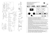
S1
C6
C5
C4
C3
RTX
L4
D2
C7
D1
C8
L3
L1
C12
D3
L2
Rl1a
D4
C1
C2
C11
R14
D8
C37
C29
T5
C31
C30
T4
C28
R15
R16
Tr9
C32
Tr10
R17
R18
C33
C34
C35
S2
R19
R20
R21
R22
D14
C36
C10
4
Service
3
2
1
C9
R6
Tr3
Tr2
R2
R3
Rl1
Rl2
D5
Rl2a
Rl1b
D6
R5
R9
T1
D10
R7
C17
D9
C16
C18
S3
R10
C19
R1
Tr1
R4
Tr4
D7
C13
ANT
R23
C39
C38
C40
P
S4
Lamp2
Fuse
T3
C27
C20
Tr5
C14
Tr6
D11
C15
Tr4
T2
C21
Lamp1
L5
Rl2b
C22
C23
Tr7
R8
R12
R13
D12
R11
C24
C25
C26
D13
W
ITALY
EC Certificate of conformity
(to EMC Directive 89/336/EEC)
This is to certify that:
The linear amplifier KLV 250
complies with the provisions of the Directive of
the Council of the European Communities on
the approximation of the laws of the Member
States relating to electromagnetic compatibility
(EMC Directive 89/336/EEC).
This declaration of conformity of European
Communities is the result of an examination
carried out by the Quality Assurance Depart-
ment of
RM Costruzioni elettroniche
in accordance with European
Telecommunicatons Standards ETS 300 684 -
300 339, of December 1995.
ATTENTION! The item is in
compliance with CE regulations if it is
used together with 27/586 filter
connected between the radio frequency
output of the unit and the antenna.
ATTENTION! Lappareil est
conforme à la norme CE si utilisé avec
le filtre 27/586 uni entre la sortie en
radio frequence de lappareil et
lantenne.
ATENCION! El aparato es conforme a
la norma CE si se utiliza juntamente con
el filtro 27/586 conectado entre la salida
a radiofrecuencia del aparato y la
antena.
ACHTUNG! Das Gerät entspricht den
CE-Prüfnormen solange der Filter 27/
586 zwischen HF-Ausgang und
Antenne eingeschleift ist.
ATTENZIONE! L'apparato è
conforme alla norma CE se usato in
combinazione con il filtro 27/586
collegato tra l'uscita a radiofrequenza
dell'apparato e l'antenna.
GB
F
E
D
I

Frequenza - Frequency - Fréquence - Frequenz - Frequencia : 10 - 30 MHz
Alimentazione - Supply - Alimentation - versorgungsspannung - Alimentación : 230 Vca ± 10 %
Assorbimento - Input energy - Courant - Stromaufnahme - Consumo : 1,6 A
Potenza d'ingresso - Input power - Puissance d'entrée - Eingangsleistung -
Potencia de entrada : 1 - 10 W AM - FM
: 2 - 20 W SSB - CW
Potenza d'uscita RF - Output power - Puissance de sortie - Ausgangsleistung -
Potencia de salida : 80 - 120 W AM - FM
:160 - 240 W SSB - CW
ROS ingresso - Input SWR - TOS d'entrée - SWR betrieb bis - ROE de entrada : 1.1/1.5
Funzionamento - Mode - Functionnement - Funktionen - Modos de emisión : AM FM SSB CW
Preamplificatore d'antenna - Antenna preamplifier : -10 - +26 dB
Fusibile di rete - Fuse on the net : 2 A
IDescrizione
L'amplificatore lineare KLV 250 è appositamente studiato per chi ha la necessità di
avere una elevata potenza per effettuare collegamenti a lunga e lunghissima distanza, al suo
interno comprende un efficiente preamplificatore d'antenna a FET che lavorando tramite
medie frequenze assicura un ottimo livello di preamplificazione senza dar luogo a fastidiose
intermodulazioni, l'ampia escursione della regolazione del livello di preamplificazione ne
permette l'utilizzo anche come attenuatore nel caso di segnali troppo forti.
INSTALLAZIONE
Dopo aver tolto l'amplificatore dal suo imballo ed aver controllato che non abbia subito
danni durante il trasporto, collegare, con una prolunga di RG58 lunga circa 90 cm.,il
ricetrasmettitore al connettore SO239 siglato con RTX e l'antenna al connettore ANT posti
entrambi sul lato posteriore dell'amplificatore, assicurarsi che l'interrutore di rete (1) sia in
posizione OFF, collegare il cavo di rete ad una presa evitando di interporre riduzioni .
Posizionare sempre l'amplificatore in modo da poter accedere con facilità a tutti i comandi
avendo cura di lasciare spazio intorno ad esso per permettere una buona ventilazione e, in
particolar modo, assicurarsi che nulla possa ostruire le griglie di areazione.
Accendere l'amplificatore tramite l'apposito interrutore (1), posizione ON, e posizionare
i comandi come è necessario considerando che:
il selettore della potenza d'uscita (2) regola il livello di amplificazione del lineare ed è
quindi possibile selezionare due livelli di potenza .
la regolazione della sensibilità del preamplificatore (5) può, quando il pre è inserito
tramite l'interruttore 4, regolare il livello di amplificazione del segnale in ricezione tra circa -10
dB e circa +26 dB, la posizione ottimale è dove la ricezione è più nitida.
l'interrutore 4 inserisce (posizione Pre. ON) o disinserisce (posizione OFF) il preampli-
ficatore d'antenna.
la posizione dell'interrutore 3 dipende dal modo di trasmissione, trasmettendo in AM
o FM usare la posizione AM, se si trasmette in SSB o CW usare la posizione SSB
l'interrutore 1, come già visto, permette l'accensione generale.
Quando l'amplificatore è in funzione si può leggere la potenza d'uscita sul Wattmetro
(6) ed il marchio (7) si illumina seguendo anche la modulazione del segnale.
ATTENZIONE !!!
Disinserire sempre la spina di rete prima di aprire l'amplificatore per qualsiasi operazione
(sostituzione fusibile ecc.). Per qualsiasi problema si consiglia di rivolgersi sempre a tecnici
SPECIFICI del settore.
Per evitare surriscaldamenti, che danneggerebbero i transistor finali, usare antenne e
cavi che sopportino una potenza di almeno 500 W con ROS non superiore a 1.5 alla massima
potenza.
Usare l'amplificatore solo per collegamenti a lunga distanza evitando di rimanere in
trasmissione per più di 5 minuti consecutivi senza intervalli ragionevoli per permettere il
raffreddamento dei transistor finali.
Garanzia mesi 24 dalla data dello scontrino o ricevuta
Si ricorda che l'utilizzo degli amplificatori lineari è regolato da leggi specifiche e quindi
se ne consiglia la visione prima dell'utilizzo e comunque la ditta costruttrice declina ogni
responsabilità derivata da un non corretto uso rispetto le norme vigenti.
La non osservanza delle istruzioni sopra scritte annulla ogni forma di garanzia che comunque
non include le parti estetiche lo strumento e i MOSFET finali.
G Description
The KLV 250 linear amplifier has been studied for who needs high power to effect long
and very long distance connections.
Inside you can find a FET antenna preamplifier, that working in medium frequencies
assures an excellent preamplification. The wide excursion of the adjustment of the preamplification
level enables its use also as tone down in case of too high signals.
INSTALLATION
After taking the linear amplifier off its package and after checking it hasn't borne any
damage during the transport, with a RG 58 extension about 90 cm. long, connect the transceiver
to the SO 239 connector RTX and the antenna to the ANT connector both placed on the back
side of the linear amplifier, be sure that the grid switch (1) is in off, connect the grid cable to
a plug avoiding reductions .
Always move the linear amplifier in such a way to be able to easily use all the commands
paying attention in leaving room around it to enable a good ventilation and, particularly, be sure
nothing can obstruct the aeration grids.
Switch the amplifier on by the switch 1 in ON and move the commands as it is needed
considering:
The output power selector (2) adjusts the amplification level of the linear amplifier, so
it is possible to select two power levels .
The switch 4 inserts (ON) or disinserts (Pre. OFF) the antenna preamplifier. When the
preamplifier is on, the adjustment of the preamplifier sensibility can adjust the amplification level
of the signal about -10 dB and +26 dB, the best position being where reception is the clearest.
The position of the switch 3 depends on the transmission mode; trasmitting in AM or
FM use the AM position, trasmitting in SSB or CW use SSB.
The switch 1, as already seen, inserts the device.
When the amplifier is on you can read the output power on the wattmeter (6) and the
trade mark (7) lightens following the modulation of the signal.
ATTENTION !!!!
Always disinsert the grid plug before opening the amplifier for any operation (fuse
replacement etc. ) however we always advise to apply to specialized technicians of the sector.
To avoid heatings, that would damage the final transistors, use antennas an cables
bearing at least 500 W power with SWR not exceeding 1,5 at the maximun power.
Only use the amplifier for long distance connections avoiding to transmit for more than
5 consecutive minutes without reasonable breaks to cool the final transistors.
Not observing the above instructions, any form of warranty will be cancelled however
it doesn't include the outside parts and the final transistors.
24 monthes warranty, from date of receipt.
Any warranty is cancelled if the above instructions are not observed.
Final MOSFETs, meter and esthetical parts are not included in the warranty.
Remember that the usage of linear amplifier is ruled by specific laws, so we advice their
vision before using, however the producer firm decline any responsibility due to a not correct
use respect the regolation.
1/2