Rockford Fosgate T1 S1-10 Manuale del proprietario
- Categoria
- Altoparlanti
- Tipo
- Manuale del proprietario

t l
VV
E
SLIM
SUBWOOFERS
T1
S1-10 •
T1
S2-10
T1S1-12 • T1S2-12
Serial
Number:
_____
_
Date
of
Purchase:
____
_
Installation
&
Operation

2
Introduction
Dear
Customer,
Congratulations
on
your
purchase
of
the
world's
finest
brand
of
car
audio
products.
At
Rockford
Fosgate
we
are
fanatics
about
musical
reproduc-
tion
at
its
best,
and
we
are
pleased
you
chose
our
product.
Through
years
of
engineering
expertise,
hand
craftsmanship
and
critical
testing
procedures,
we
have
created
a
wide
range
of
products
that
reproduce
music
with
all
the
clarity
and
richness
you
deserve.
For
maximum
performance
we
recommend
you
have
your
new
Rockford
Fosgate
product
installed
by
an
Authorized
Rockford
Fosgate
Dealer,
as
we
provide
specialized
training
through
Rockford
Technical
Training
Institute
(RTTI).
Please
read
your
warranty
and
retain
your
receipt
and
original
carton
for
possible
future
use.
Great
product
and
competent
installations
are
only
a
piece
of
the
puzzle
when
it
comes
to
your
system.
Make
sure
that
your
installer
is
using
100%
authentic
installation
accessories
from
Rockford
Fosgate
in
your
installation.
Rockford
Fosgate
has
everything
from
RCA
cables
and
speaker
wire
to
power
wire
and
battery
connectors.
Insist
on
it!
After
all
,
your
new
system
deserves
nothing
but
the
best.
To
add
the
finishing
touch
to
your
new
Rockford
Fosgate
image,
order
your
Rockford
accessories
,
which
include
everything
from
T-shirts
to
hats.
Visit
our
web
site
for
the
latest
information
on
all
Rockford
products;
www.
rockfordfosgate.
com
or,
in
the
U.S.
call1-800-669-9899
or
FAX
1-800-398-3985
.
For
all
other
countries,
call
+001-480-967
-3565
or
FAX
+001-480-966-3983.
Table
of
Content
2
Introduction
3
Specifications
4-5
Enclosures
Sealed
or
Vented
Wiring
6-7
Additional
Languages
French
Spanish
German
Italian
8
Limited
Warranty
Information
If,
after
reading
your
manual,
you
still
have
questions
regarding
this
prod-
uct,
we
recommend
that
you
see
your
Rockford
Fosgate
dealer.
If
you
need
further
assistance,
you
can
call
us
direct
at
1-800-669-9899
.
Be
sure
to
have
your
serial
number,
model
number
and
date
of
purchase
available
when
you
call.
Safety
This
symbol
with
"WARNING
"
is
intended
to
alert
the
user
to
the
presence
of
important
~WARNING
instructions.
Failure
to
heed
the
instructions
will
result
in
severe
injury
or
death.
This
symbol
with
"CAUTION"
is
intended
to
alert
the
user
to
the
presence
of
important
~
CAUTION
instructions.
Failure
to
heed
the
instructions
can
result
in
injury
or
unit
damage.
•
To
prevent
injury
and
damage
to
the
unit,
please
read
and
follow
the
instructions
in
this
manual.
We
want
you
to
enjoy
this
system,
not
get
a
headache.
•
If
you
feel
unsure
about
installing
this
system
yourself,
have
it
installed
by
a
qualified
Rockford
Fosgate
technician.
•
Before
installation,
disconnect
the
battery
negative
(-)
terminal
to
prevent
damage
to
the
unit,
fire
and/or
possible
injury.
©2014
Rockford
Corporation.
All
Rights
Reserved.
ROCKFORD
FOSGATE
and
associated
logos
where
applicable
are
registered
trademarks
of
Rockford
Corporation
in
the
United
States
and/or
other
countries.
All
other
trademarks
are
the
property
of
the1r
respective
owners.
Specifications
subject
to
change
without
notice

Mode
l
T1S1-10
T1S2-10
T1S1-12
No
minal
Impedan
ce
(O
hms)
Freq
u
en
cy Re
sp
ons
e
(H
z)
Voice
Co
il
Diame
te1
-
in
ch
(
mm)
Disp
l
ac
em
en
t-
cu
ft
.
(
Liter)
Fs
Free A
ir
R
es
onance
(Hz)
O
ts
Vas- cu.
It
(
Lite
r)
Xm
ax
-
inc
h
(mm)
SPL
(
dB@
1w/1
m)
Power
Hand
ling- W
atts
500/1000
500/1000
600
/12
00
(
RMS/Pe
ak)
,.
,
••
'"'''•Q
.,.
C
EA
20
31
§
~
:
Power
han
d
li
ng
on
R
ockford
Fos
gate
confor
m
to
CEA
~
2
0
3
1
in
dust
ry
sta
ndards.
Th
is
me
a
ns
you
r
0
':'
~
f
po
we
r
un
de
r
cont
in
u
ous
clemand,
no
t
in
st
an
taneo
us
po
w
er
hand
lin
g that o
ver
ti
me
can
dama
ge v
oic
e
coil
s.
1
.f·2D3\t.o;
V
ERIFIED
W
IT
H~
VERI
FIED
W
IT
H
KLIPP
EL
Specifications
T1S2-12
600
/1
200
has the
ca
p
ac
i
ty
to ha
nd
le
K
Ll
P P
El
To
adorn
the
'V
er
ified
with
Kl
ippel'
m
ark
,
the
qua
l
if
yi
ng
comp
any'
s lou
dsp
e
ake
r
engi
nee
r
in
g
pe
r
son
n
el
m
us
t
be
tr
ai
ned
and
cer
ti
fied by
"-.__../
K
li
pp
el
pr
io
r to us
ing
the
thre
e
se
para
te
Klipp
el
sys
te
ms
to d
es
ign
, deve
lo
p a
nd
te
st Rockf
ord
Fo
sg
ate
has
ma
de
th
e i
nves
tm
ent
in Kli
ppel
to
del
iv
er
th
e
be
st
po
ss
ib
le
sp
eake
rs
an
d
s
ub
woofe
rs
to
their
cu
sto
mer
s.
A
A-
Ov
erall
Di
am
et
e
r-
in
ch
(
rn
m)
B-
Sc
rew
Hole
Di
a
.-
in
ch
(
mm
)
0 -
M
ounting
Depth
inc
h
(m
rn
)
B
PUSH
to
attach
wir
e
...-
---
PUSH
to
attach
wire
3

4
Enclosures
Carton
Contents
•
T1
Subwoofer
with
Trim
Ring
•
(12)
Mounting
Screws
•
(4)
Trim
Ring
Screws
•
(1)
Socket
head
driver
bit
•
Installation
and
Operation
Manual
Recommended
Enclosures
This
manual
outlines
two
specific
types
of
enclosures
that
provide
distinctly
dif-
ferent
performance.
This
section
is
to
help
you
decide
which
type
is
best
for
your
application.
Sealed
Enclosures
Sealed
enclosures
are
the
simplest
to
build.
The
most
important
part
of
bui
l
ding
a
sealed
enclosure
is
to
make
sure
that
the
enclosure
is
airtight.
Using
glue
and
some
type
of
sealant
on
all
seams
will
ensure
solid
construction
and
prevent
air
leaks
.
The
box
volume
will
directly
impact
the
performance
of
the
speaker.
Larger
enclosures
will
provide
flatter
response
and
deeper
bass
where
s
maller
boxes
will
provide
a
bump
in
the
response
curve
and
generally
higher
output
for
greater
SPL.
Advantages
of
sealed
enclosures:
•
Small
enclosures
•
Linear
(Flat)
response
•
No
port
noise
•
High
power
handling
at
all
frequencies
•
Excellent
for
sound
quality
•
Extended
low
frequency
output
when
compared
to
vented
enclosures
Vented
Enclosures
Vented
enclosures
vary
only
from
the
sealed
enclosure
in
that
a
vent
or
port
is
added
to
"tune"
the
enclosure.
The
enclosures
recommended
are
designed
for
great
overall
performance
.
Larger
boxes
tend
to
be
easy
to
tune
to
lower
frequen-
cies
while
medium
and
small
boxes
are
easier
to
tune
to
higher
frequencies.
The
vented
design
is
le
ss
linear
in
re
s
ponse
than
the
sealed
box
but
with
noticeably
more
output
at
the
tuning
frequency.
Advantages
of
vented
enclosures:
•
Higher
average
output
than
sealed
•
Tuning
frequency
can
be
easily
adjusted
by
changing
port
length
•
Deep
bass
respon
se
with
lower
power
requirements
•
Great
for
high
output
with
limited
power
Vented
vs
Sealed
The
graph
shown
here
is
a
sample
of
how
the
F3
drop-off
point
differs
between
sealed
and
vented
enclo
s
ures
.
120.0
--
t--+
- -
-
1--
.
t---
·-
1--
110.0
~=:
··
100
.0
90
.0
t--
-
..
-
~
-
-t-
1--
t--
t-
·
80.
0
1--
1--
70.0
- .. -
t--
60.0
10.0
20
.0
400
60.0 80.0 100.0
·-·
Sea
led
Box
-
Vented
Box
Frequency,
Hz
- -
!-
-·
··-
- -
1--
+--
-
+- ·-
+--
. .
--
1--
·
-
1
-
~
-=-1--
·--
1--
·
··-
1-
-
1-
f-
200
.0
Building
an
Enclosure
To
work
properly,
the
walls
of
the
enc
l
osure
must
be
rigid
and
not
flex
when
sub-
jected
to
the
high
pressures
generate
d
by
the
speaker's
operation.
For
optimum
performance
,
we
recommend
using
3/4"
MDF
(Medium
De
ns
i
ty
Fiberboard)
and
internal
brac
i
ng.
The
enclosure
should
be
glued
together
and
secured
with
na
i
ls
or
screws.
Calculating
Volume
Calculating
volume
is
merely
a
matte
r
of
measuring
the
dimens
i
ons
in
inches
and
using
the
fo
r
mula:
H x W x D
divided
by
1728
(cubic
feet)
.
See
block
below.
Box
Volume
Divided
by
(cubic
feet)
Height"
x
Width"
x
Depth"
1728
If
two
facing
sides
are
of
uneven
leng
th,
add
them
together
and
divide
by
two
to
take
the
ave
r
age.
Using
this
numbe
r
wi
ll
give
you
the
volume
without
the
necessity
of
calculating
the
box
in
sections
and
adding
the
sections
together.
The
thickness
of
the
baffle
material
reduces
the
internal
volume
so
this
mus
t
be
subtracted
from
the
outside
dimensions
to
determi
ne
the
internal
volume
.
The
speaker
itself
also
reduces
the
internal
volume
.
The
amount
of
air
displaced
by
each
model
is
listed
on
the
specif
i
cation
sheet
and
should
also
be
subtracted
fro
m
th
e
gross
volume
calculation.
Sealed
Enclosure
NOTE:
Vb
is
the
internal
volume,
before
any
speaker
and/or
port
dis-
placement
is
added.
All
external
dimensions
were
based
on
the
use
of
3/4"
(1.90cm)
materials.
NOTE:
When
using
enclosures
othe
r
than
recommended,
call
Technical
Support
for
correct
application.
Optimum
Sealed
Enclosure
Recommendation
Sealed
Enclosures
10"
Total
Internal
Volume
cu.
ft
.
(Liter)
0.80
(22.62)
Woofer
D
is
placement
cu.
ft.
(Liter
)
0.03
(0.8
2)
Vb
-
Int
e
rn
al
Area
cu.
fl.
(Liter)
0.77
(
218)
F
3
-
3d
B
Po
in
t
(Hz)
40
.3
Ole
-
Enclosure
Damping
1.10
H-
Height
-
inch
(em)
12
(30.48)
W-
Width
-
inch
(em)
18
(45.72)
D-
Depth
-i
nc
h
(em)
95(24
.1
3)
Recommended
Sealed
Enclosure
Volume
Range
Sealed
Enclosures
Vb-
Volume
range
cu.
ft.
(Liter)
10"
0.5
to
1.0
(14.16
to
28.32)
12"
1.10
(30.87)
0.05
(1.42)
1.
05
(
29.45
)
39
.9
1.
18
1
3.
0
(33
.
02)
22.0
(55
88)
9 5
(24.13)
12"
0.75
to
1.25
(21.24
to
35.40)

Vented
Enclosures
NOTE:
Vb
is
the
internal
volume,
before
any
speaker
and/or
port
dis-
placement
is
added.
All
external
dimensions
were
based
on
the
use
of
3/4"
(1.90cm)
materials.
NOTE:
When
using
enclosures
other
than
recommended
,
call
Technical
Support
for
correct
application.
3/4"
MDF
I I
I I
I I
:
~
:
Optimum
Vented
(Ported)
Enclosure
Sizes
Vented
Enclosures
10" 12"
Total
Internal
Volume
cu.
ft.
(liter)
1.5
(42.48)
2.0
(56.63)
Woofer
Displacement
cu.
ft.
(Liter)
0.03
(0
.
82)
0.
05
(1.42)
Port
Displacement
cu.
ft.
(Liter)
0.12(3.4)
0.
09
(2.55)
Vb-
Internal
Area
cu.
ft.
(Liter)
1.35
(38
.
23)
1.86
(52.67)
F
8
-
Tuning
Frequency
(Hz)
40
35
F
3
-
3dB
Point
(Hz)
30
28
H -
Height
-
inch
(em)
12.0
(30.48)
14
.5
(36.83)
W-
Width-
inch
(em)
20.0
(50.8)
22
.5
(57
.
15)
D-
Depth
-
inch
(em)
15.0
(38.1)
14
.
25
(36
.
2)
P-
Port
Diameter
and
Length-
inch
(em)
4x14.25
4
X
13
(10.16
x36.2)
(10
.
16
x33.02)
NOTE:
The
port
shown
can
be
placed
on
any
face
of
the
enclosure
as
long
as
the
port
ends
are
not
obstructed
.
NOTE:
When
using
vented
enclosures,
for
maximum
reliability
and
power
han-
dling
ensure,
that
a
subsonic
or
"infrasonic"
filter
at
or
above
27Hz
is
used
so
that
only
usable
low
frequency
signals
are
sent
to
the
subwoofer.
Enclosures
Wiring
Configurations
By
varying
the
wiring
configuration
of
your
speakers
you
can
create
an
impedance
load
to
match
your
system.
Altering
the
wiring
configurations
gives
a
range
of
options
for
impedance
loads.
Series
,
Parallel
,
or
Series-Parallel
wiring
configura-
tions
are
different
techniques
for
wiring
speakers
that
provide
different
loads
.
Se-
ries
configuration
is
a
string
method
where
speakers
are
wired
end
to
end.
Parallel
configuration
uses
two
or
more
speakers
wired
across
common
terminals.
Series-
Parallel
configuration
combines
both
techniques.
Choose
the
wiring
diagram
that
corresponds
to
the
number
of
woofers
and
the
impedance
of
your
amplifier.
Parallel
Wiring
(2)
2
ohm
SVC
Speaker=
1
ohm
Load
Series
Wiring
(2)
1
ohm
SVC
Speaker=
2
ohm
Load
Subwoofer
Crossovers
There
are
two
operational
types
of
crossovers,
passive
and
active
.
Passive
cross-
overs
(coils
or
inductors)
are
placed
on
the
speaker
leads
between
the
amplifier
and
speaker.
An
active
crossover
is
an
electronic
filter
that
separates
the
audio
signal
fed
to
different
amplifiers
.
For
optimum
subwoofer
performance,
we
recom-
mend
using
an
active
80-1
OOHz
low-pass
crossover
at
12dB/octave.

6
Fran~ais
Enceintes
recommandees
Ce
manuel
decrit
deux
typ
es
particuliers
d'enceinte
s
au
x
performances
tout
a
fait
d
is
tin
ctes.
Cette
section
vous
permettra
de
decider
celui
qui
vous
co
nviendra
le
mieux.
Enceintes
Etanches
Les
en
ce
inte
s
et
anc
hes
sont
les
plu
s f
ac
ile
s a fa
briquer.
A
eel
egard,
Ia c
ho
se
Ia
plu
s im
por-
tant
e
dan
s le
ur
fa
br
i
cation
e
st
de
vou
s
ass
ur
er
qu'
e
lle
s
son
t
vraiment
he
rm
e
tiques
.A
pp
l
ique
z
de
Ia
co
lie
et
un
produit
d'
etancheite
sur
taus
le
s
joints
pour
solidifier
!'ensemble
et
emp
e
cher
toute
fuite
d'air.
Le
volume
du
caisson
influe
directement
sur
Ia
performance
du
haut-
p
arleur.
Les
enceintes
de
plus
grand
e
dimension
delivrent
une
r
ep
onse
uniforms
en
freque
nce
avec
des
graves
profonds
alor
s
que
les
enceintes
plus
petit
es
ant
une
courbe
de
re
po
nse
plus
pr
noncee
et
un
rendement
generalement
superieur
pour
un
niveau
de
pression
a
co
u
tique
plu
s
eleve.
Avantage
des
enceintes
etanches:
• Pe
tit
es
en
ce
int
es
• Re
pon
se
lin
e
air
e
(uniforme)
•
Pas
de
bruit
d'event
•
Puissance
elevee
sur
tout
es
les
frequences
•
Excellentes
en
ce
qui
concerne
Ia
qua
lite
duson
Enceintes
A
Event
Le
s
enceinte
s a
event
se
di
s
tingu
e
nt
des
enceintes
e
tanche
s
du
fait
qu'on
y ajo
ut
e
un
ev
e
nt
au
po
rt
po
ur
l
es
" ac
cord
er
...
L
es
ence
int
es
re
co
man
dees
son!
co
nv
ue
s
pou
r o
f-
frir
d'e
xce
llent
es
pe
rformanc
es.
II
es
t
ge
n
era
l
eme
nt
plu
s f
ac
il
e
d'accorder
l
es
ca
i
ssons
plu
s
grand
s
pour
!
'o
bt
e
nti
on de
basses
fr
e
qu
ences
et l
es
caisso
ns moyens
et
pe
tit
s
po
ur
des
frequences
plus
elevee
s.
Le
s
enceintes
a
event
ant
une
reponse
main
s
lineaire
que
les
enceintes
etanch
es
mais
degagent
nettem
e
nt
plu
s
de
pui
s
sance
a
Ia
frequence
d'acco
rd.
Avantages
des
enceintes
a
event
:
•
Rendem
e
nt
moyen
superi
e
ur
par
rapport
aux
modeles
e
tanche
s
• La
fr
eque
n
ce
d
'acco
rd
pe
ut
etr
e f
ac
il
eme
nt
r
eg
l
ee
en cha
ng
ea
nt
Ia lo
gueu
r
de
!'event
•
Repr
od
uc
ti
on pr
ofo
nde
de
s b
asses
av
ec
une
pui
ss
an
ce
d'entr
ee
mo
in
dre
• Ex
ce
ll
e
nt
choix po
ur
un
re
nd
eme
nt
el
eve
a Ia
ibi
e
pui
ssa
n
ce
d'
e
ntr
ee
Construire
Un
Caisson
Po
ur
fonctionner
convenabl
e
ment
les
parois
du
ca
i
ss
on
doivent
etre
rigides
lors
qu'
elles
so
nt
soumises
aux
haute
s
pre
ss
ions
dues
au
fon
c
ti
onn
ement
du
haut-parleur
.Nous vous
recommandons
d'
utili
s
er
de
s
panneau
x
de
bois
agglom
er
e a ha
ute
au
moyenne
d
ens
ite
de
parti
c
ul
es
de
typ
e
"MDF
"
.C
es
pann
e
au
x s
on!
disponibl
es
dans
Ia
plup
a
rt
des
ma
gas
ins de
bri
co
l
age
.
Po
ur
un
ca
i
sso
n de
gran
d vo
lum
e
il
es
t r
eco
mm
a
nd
e de pl
acer
des
renfor
ts a
l'int
e
ri
e
ur
du
ca
i
sso
n.
Le
s d
ifferenl
s
co
t
es
devronl
e
ire
c
olle
s (
co
ll
e a b
ois
) et v
isses
(ou
eve
nt
ue
ll
ement
clou
es
).
II
es
t r
ec
omman
de
de
me
ttr
e un
joint
de s
ili
co
ne dans l
es
aret
es
int
e
rn
es
du
ca
i
ss
on
a
fin
d'e
vit
er
le
s
fuite
s
d'
a
ir.
Calcu
duVolume
On
c
alcule
le
volume
en
m
es
ur
a
nt
Ia
dimension
de
c
haque
co
te
et
en
utilisant
Ia
fo
rm
ule
s
ui
vant
e:
Volume
du
caisson
Divise
pres
(litres)
Hauteur
(em)
x
Longueur
(em)
x
Largeur
(em)
1000
Si l
es
du
e
co
t
es
qui
se
f
on
t f
ace
n
'on
t
pas
Ia meme longue
ur,
a
ddit
io
nn
ez
l
es
et
divi
sez
le r
es
ult
at
par
deux
po
ur
ob
te
nir
Ia mo
yenn
e
des
deux lo
ngueur
s
.Utili
sez
le
no
mb
re
ainsi
o
btenu
dan
s
Ia
fo
rmule
pou
r de
terminer
le
litrag
e
.C
e
tt
e
me
th
o
de
permet
d'obtenir
le
vo
lume
du
ca
i
sso
n
sa
ns
de
vo
ir
fa
ir
e
de
ca
lc
ul
s comp
liqu
es
de
sec
ti
on
de
vo
lume
.
L'
ep
aisseu
r
du
mate
ri
au
do
ni
es
t
fa
it le
ca
i
sso
n re
du
it le v
olume
intern
e de
ce
lui
-c
i.
Lor
s
qu
'
on
mes
ure l
es
cotes
du
caisso
n
il
ne
ta
ut
do
ne p
as
oub
li
er
d'o
ter d
es
mes
ur
es
l
'epa
i
sse
ur
du
materiau. Le
hau
t-pa
rl
e
ur
lui
-meme
dim
i
nu
e le
vo
lume
in
I
ern
e
du
ca
i
sso
n. Le vo
lum
e d'
ai
r dep
la
ce par
c
haqu
e m
od
ele
de
ha
ut
-
pa
rle
ur
es
t r
ep
ri
s dans l
es
spec
ifi
ca
ti
ons
tec
hniqu
es
et
do
it
ega
le-
me
nt
etre
so
u
st
ra
it
du vo
lum
e tota
l.
Configuration
du
cablage
En
va
ri
a
nt
Ia
co
nfi
g
ur
a
tion
du
ca
bl
age
de
v
as
ha
ut-
pa
rl
eurs,
vous
po
uve
z cr
ee
r
un
e
charge
d'
imp
eda
n
ce
co
rre
spo
nd
a
nt
a
vo
t
re
system
e.
La
modif
ica
ti
on d
es
conf
i
gu
ra
ti
ons de
cab
l
age
o
ff
re
t
ou
t un ch
oix
d'op
ti
ons
en
ce
q
ui
co
n
ce
rn
e Ia char
ge
d'
i
mpeda
n
ce
. L
es
ca
bl
ages
se
-
ri
e,
para
ll
e
le
, au
ser
i
e/
paral
le
le
so
nt
de
s t
ec
hniqu
es
pe
rm
e
tt
a
nt
de
cab
ler l
es
ha
ut
-p
arle
ur
s
de man
iere
a
prod
ui
re
d
es
char
ges
di
ffe
re
nt
es.
La
co
nfi
g
ur
a
ti
on
se
ri
e
co
nsiste a
cab
ler l
es
ha
ut
-p
ar
le
ur
s a Ia cha
in
e,
bo
ut
a bo
ut.
La
co
nfi
g
ur
at
ion para
ll
ele
utili
se
de
ux ou
pl
us
ieur
s
ha
ut
-p
ar
leu
rs
bran
ch
es
s
ur
de
s ba
rn
es
co
mm
une
s.
La
co
nfi
g
ur
at
i
on
se
ri
e/para
ll
ele
comb
in
e
l
es
deux
tec
hni
qu
es
.Choisi
ssez
le
sche
ma ci-d
esso
us
qui
co
rr
es
pond au
nom
bre de
ha
ut-
pa
rleur
s
de
gr
av
es
et a
!'im
ped
an
ce
de
vo
t
re
amp
l
i.
Filtres
de
subwooler
On
di
s
ti
ng
ue deux
typ
es
de
filtr
es
opera
ti
on
nels : p
assif
et
ac
tif.
Les
filt
res
p
ass
if
s
(bob
i
nes
ou
in
du
cte
u
rs
)
so
nt
pl
aces
s
ur
l
es
fil
s de haut-
pa
rl
eu
r,
en
tre
l
'a
mp
li
et
le ha
ut
-pa
rl
eu
r.
Un
f
iltr
e
ac
tif
es
t
un
f
iltr
e el
ec
troniqu
e
qu
i
sepa
re le s
ign
al a
ud
io
en
vo
ye a
di
ff
eren
ts amp
li
s.
Pour
ob
te
nir
une
pe
r
fo
rm
an
ce
op
tim
ale du s
ubw
oo
fer, nous
reco
mm
a
nd
ons
!'utili
sa
ti
on
d'
un
filt
re
ac
lif
passe-
b
as
80-
10
0 Hz a 12 d
B/oc
t
av
e
Espanol
Cajas
recomendadas
Este
manua
l del
inea
dos
tipos
esp
ecff
i
cos
de
cajas
que
produ
cen
rendimi
entos
inconfund
-
iblement
e d
if
e
rentes.
Esta
secci6n
es pa
ra
ay
udarle
a
decidir
cual tipo
es
el
mejor
para
su
aplicaci6n
.
Cajas
CERRAOAS
Las
caja
s ce
rr
ad
as
son
la
s
mas
facil
es
de
h
ac
er.
La
part
e
mas
im
po
rt
a
nt
e
de
Ia
c
on
s
truc
ci6n
de
una
caj
a
ce
rr
ada
es
garantizar
su
he
r
me
ti
s
mo.
El
u
sa
de
pega
nte y al
gu
n
tipo
de
sellador
en
todos
l
os
bo
rdes
garantizara
una
co
n
st
r
uc
ci6n
salida
y
evita
ra
f
ug
as
de
a
ire.
El
volumen
de
Ia
caja
imp
ac
ta
directamente
el
r
end
imie
nto
del
altavoz.
La
s
ca
j
as
mas
grandes
ofre
ce
n
una
respu
es
ta m
as
plana
y
un
bajo
m
as
pr
of
undo,mientras
que
l
as
mas
peq
uenas
ofrecen
un
incremen
to
en
Ia
curva
de
respuesta
y
gene
ral
mente
una
salida
mayo
r,
pa
ra
un
mayor
NPS
.
Ventajas
de
l
as
cajas
cerradas
:
• Cajas
pe
que
n
as
•
Re
s
pu
esta
lin
eal (plan
a)
•
No
hay
ru
i
do
del
or
ificio
•
Capacid
ad
de
alta
palencia
en
toda
s las fre
cuencias
• Ex
cele
ntes
pa
ra
Ia
calidad
del
sonid
o
Cajas
con
Orificios
Las
caja
s
co
n
or
ificios
solo
se
difer
enc
i
an
de
las
cerradas
en
qu
e
se
l
es
ha
ce
un
orificio
pa
ra
"sintoni
z
arl
as
."
La
s
cajas
recom
e
nd
adas
son
di
s
en
a
da
s
para
un
gran
r
en
dimiento
gener
a
l.
L
as
ca
j
as
g
ra
ndes
ti
en
de
n a
se
r f
aci
l
es
de
sin
toni
za
r en l
as
fr
ec
ue
nc
i
as
gra
v
es
,mi
e
ntr
as
qu
e
m
ed
ian
as
y
peq
u
efias
so
n m
as
f
ac
il
es
de sin
toni
za
r en l
as
fr
ec
u
en
ci
as
mas ali
as.
El di
se
no
co
n
orifi
ci
os
es
de
un
a
re
sp
u
es
ta men
os
li
nea
l
qu
e
el
de
Ia c
aj
a
ce
r
rada
,
per
o
tierie
un
a
sa
li
da
notablement
e
mayo
r
en
Ia
frecuencia
de s
int
o
nizaci6n.
Ventajas
de
las
cajas
con
orificios:
•
Un
pro
me
dia
de
salida
mayor
que
l
as
cer
r
adas
•
La
frecu
encia
de
s
intonizaci
6n
se
aj
u
sta
fa
cilmente
al
cambia
r
Ia
lo
ng
it
ud
del
orificio
•
Re
s
pue
st
a de
bajo
profunda
con
m
enos
ex
ig
encia
de
pal
e
nc
ia
•
Fa
bul
osas
para
sa
li
da
a
lta
co
n pale
nc
ia l
imit
ada
Construcciiin
de
una
caja
Pa
ra
un
bu
en
fu
ncionami
e
nt
o l
as
par
edes
de
Ia caja deben
se
r
rig
idas
y
nose
deben do
bl
ar
cuando
se
an
so
metidas
a
Ia
gran
presi
on
qu
e
ejer
ce
el
fun
c
ionami
en
to d
el
altavo
z.
R
ec
o-
mendamos
usa
r ma
dera
comprimid
a
de
me
diana
densidad
,
de
1
.9
em
o lib
ra
de
media
den-
sidad.
Si
Ia
ca
ja es
muy
grande
es
n
ecessa
r
ia
ref
o
rzarla
internam
e
nt
e.
L
as
juntas
deben
s
er
encoladas
y a
se
gurada
s con
tornillo
s o
grapas
.
lnternamente
io
s
bo
r
des
d
eben
s
er
sellado
s
co
n silico
na
pa
ra
p
re
ve
ni
r
las
fuga
s de a ire.
La
co
la para madera
es
Ia mejor opci6n.
Calculo
deVolumenes
Para
ca
lcu
la
r el
volu
me
n
so
lo
se
han
de
med
ir
l
as
di
mens
ion
es
en
ce
ntr
me
tro
s y a
pli
ca
r Ia
for
mul
a:
Volumen
du
Ia
caja
Dlvidldo
por
(en
litros)
Alto(cm)xAncho(cm)
x
Prolundidad(cm)
1000
Si
do
s
ca
r
as
op
u
estas
son
de
dif
eren
te
t
ama
fi
o,
slime
l
as
y
divi
da
el t
ota
l par d
os
pa
ra ob-
tener
el
pro
m
ed
i
o.
U
sa
nd
o esta t
ec
ni
ca
se
ahor
ra
ra el
ca
lc
ulo
p
ar
secc
i
on
es
. El
es
p
es
or
del
m
ate
ri
al
con
que
es
ta
co
n
st
rui
da
Ia
ca
ja r
ed
u
ce
el
vo
lu
me
n
int
e
rn
o,
de
ma
nera que ha
de
r
es
tar
se
de
l
as
dim
ension
es
ex
te
ri
ores
para dete
rmin
ar
el v
olu
m
en
inter
io
r. La
ca
ntid
ad
de
ai
re
que
oc
u
pa
ca
da
mod
el a
vi
ene
espec
ifi
ca
do en Ia hoja de
ca
r
ac
terfs
ti
cas
y t
am
bi
en
debe
su
st
r
ae
r
se
para
o
bt
e
ner
el
vo
lum
en neto inte
ri
o
r.
Configuraciones
del
cableado
AI
va
ri
ar Ia
conf
ig
ur
ac
i6n del
ca
bl
eado
de
los al
ta
v
oc
e
s,
us
ted
puede
crea
r
un
a
imped
ancia
de
ca
rga
qu
e iguale a su sis
tema.
La a
lte
r
aci6
n de
Ia
co
nfi
gu
rac
i
6n
de
l
os
ca
bl
es
da
una
ga
ma de
opc
i
ones
para
im
pe
dancia
de
car
ga.
L
as
co
nfigura
cion
es
en
se
ri
e,
para
lela o en
s
eri
e
-pa
rale
la
so
n t
ec
ni
cas
dif
ere
nt
es
pa
ra el
cab
l
ea
do de los a
lt
avo
ce
s
qu
e
of
r
ece
n
ca
r
gas
di
fe
re
nt
es
. La c
onfi
gu
r
ac
i6n en serie
es
un metoda en
cade
na
en
el
que
l
os
a
lt
avoces
se
co
n
ec
tan de pun
ta
a
punt
a. La
co
nf
igurac
i6n paralela u
sa
d
os
o
mas
a
lt
av
o
ces
co
n
ec
tad
os
a lo la
rg
o
de
term
in
at
es
en
co
mun. La config
ur
ac
i6n en
se
r
ie
-
para
lela
co
mb
in
a
ambas
t
ec
-
ni
cas
.
Esco
ja
el
di
ag
rama
que
co
rr
espo
nda al
nu
me
ro
de
a
lt
av
oces
pa
ra
so
ni
dos
gr
aves y
Ia
imped
anc
ia
de
su
amp
li
ficado
r
Fillros
deTransicion
del
altavoz
para
sonidos
graves
(Subwooler
X·Over)
H
ay
d
os
ti
pos
f
unc
ional
es
de f
ilt
ros
de transici6n,
pas
iv
os
y
ac
ti
vos
. L
os
pas
iv
os
(b
o
bin
as
o
in
duct
ores
)
se
c
on
ecta
n a l
os
ca
bl
es
de
l alt
av
oz, e
ntr
e el
am
pl
ificad
or
y el a
lt
avoz.
Un f
iltr
o de
transici6n
ac
ti
vo
es
un
f
ilt
ro
el
ec
tr
6
ni
co
que
sepa
ra Ia
sena
l de audio a
li
me
nt
ada a di
fe
re
nt
es
a
mpli
fica
dores
Pa
ra
un
rend
imi
e
nt
o
6ptimo
de
l a
lt
avoz
para
so
n
idos
gr
a
ves,
reco
me
nd
amos
el u
sa
de un fil
tro
de
transici6n
ac
ti
vo
de
S0
-1
00
Hz,
paso
ba
jo a 12
dB
/
oc
tava

Deutsch
Empfohlene
Gehliuse
DieseAnleitung
beschreibt
zwei
spezifischeTypen
von
Gehausen,
die
grundsatzlic
h
ver
-
schiedene
Performancemerkmale
bieten
.
DieserAbschnitt
soli
Ihnen
dabei
helfen
zu
entscheiden,welcher
der
besteTyp
fUr
lhreAnwendung
ist.
Geschlossene
Gehause
Geschlossene
Gehause
lassen
sich
am
leichte
ste
n
bauen
.
Der
wichtigsteA
s
pekt
beim
Bau
eines
geschlossenen
Gehauses
ist
zu
gewahrleisten
,
dass
es
luftdicht
ist.
DieVerwendu
ng
von
Klebstoff
und
anderen
Dichtungsmitteln
an
allen
Fugen
gewahrleistet
eine
solide
K
on-
struktion
und
verhindert
Luftverlust.Das
Gehausevolumen
wirkt
sich
unmittelbar
auf
die
Per-
formance
des
Lautsprechers
aus.GroBere
Gehause
bieten
eine
fl
achere
Reaktion
und
tiefere
Basse
,
wohingegen
kleinere
Gehause
eineAbweichung
in
der
Reaktionskurve
bieten
und
im
Allgemeinen
durch
hohere
Lei
stung
zu
einem
hoheren
Schalldruckpegel
tohren.
Vorteile
von
geschlossenen
Gehiiusen:
•
Kleine
Gehiiuse
•
Lineare
(!Iache)
Reaktion
•
Keine
Offnungsgerausche
•
Hohe
Nennbelastbarkeit
in
allen
Frequenzbere
ic
hen
•
Ausgezeichnete
Klangqualita
t
Beliiftete
Gehliuse
Be!Oftete
Gehause
unterscheiden
sich
von
geschlossenen
Gehausen
nur
in
sofern
.
als
dass
ein
Luftschlitz
bzw.
eine
Offnung
hinzugefUgt
wird
,
um
das
Gehau
se
zu
,stimme
n
".
Die
emp
-
fohlenen
Gehause
s
ind
fUr
hervorragende
Gesamtperformance
konstruiert.GrtiBere
Gehause
l
asse
n
sich
in
der
Regel
Ie
ic
h
ter
auf
niedrigere
Frequenzen
abstimmen,wohingegen
s
ich
mit
-
tlere
und
kleine
Gehause
Ieichter
auf
hohere
Frequenzen
abstimmen
lassen.Das
be!Uftete
Design
zeigt
eine
weniger
lineare
Reaktion
als
das
geschlossene
Gehause,
erbringt
jedoch
eine
feststellbar
hOhere
Leistung
auf
der
abgestimmten
Frequenz.
Vorteile
von
beliifteten
Gehiiusen:
•
Hoh
ere
Durch
sch
nitt
s
lei
stung
als
geschlossene
Geha~se
•
Abstimmfrequenz
kann
Ieicht
durch
Anderung
der
Offnungslange
a
gepasst
werde
n
•
Ti
efes
Bassverhalten
bei
geringerem
Kraftbedarf
•
Gut
geeignet
fOr
hohe
Leistung
bei
beschrankter
Kraft
Bau
des
Gehliuses
Um
ordnungsgemaB
zu
funktio
n
ieren,mOssen
die
Gehaus
ewa
nde
steif
sein
und
dOrfen
nic
ht
nachgeben
,
wenn
sie
dem
hohen
Druck
ausgesetzt
sind
,
der
bei
Betrieb
des
Laut
spreche
rs
entsteht.
FOr
optimale
Performance
empfehlen
wir
Faserpl
atte
mittlerer
Dichte
(Starke
ca
.
1,9
em)
und
interneAussteifungen
.
Das
Gehause
wird
verleimt
und
mit
N
ageln
oder
Schrauben
befestigt.Da
Faserplatte
luftdurc
hl
assig
ist,
wird
geraten
,
das
Gehause
von
auBen
mit
Poly-
ur
et
han
zu
behandeln
.
Berechnung
desVotumens
Z
ur
Berec
hnung
desVolumens
e
infa
ch
die
MaBe
feststellen
und
folgende
Forme!
anwend
en
:
Gehiiuse-Volumen
Vorbei
geteilt
(Liter)
Hiihe
(em)
x
Breite
(em)
xTiele
(em)
1000
Sind
zwei
gegenOber
liegende
Seite
n
un
g
lei
ch
l
ang,
die
Durchschnittslange
der
beiden
Seiten
berechnen
.
DasVolumen
l
ass!
sich
mithilfe
dieser
Zah
t
berechnen,
ohne
das
Geha
us
e
inAbs
chn
itten
berechnen
zu
mUssen
.
Die
Starke
des
Resonanzwandmaterials
redu
z
iert
das
lnnenvolum
en
und
muss
dah
er z
ur
Fe
sts
tellung
des
lnn
envo
lum
ens
vomAuBenvolumen
s
ubtr
ah
i
ert
w
erden.De
r
Laut
sp
recher
se
lb
st
reduziert
das
lnn
e
nvolum
en
ebenfal
ls.
Die
Lu
ft
-
verdrangung
fUr
jedes
Modell
i
st
unterTe
c
hnische
Daten
aufgefUhrt
und
muss
bei
d
er
Gesa-
mtkalkulation
de
s
Volum
ens
ebenfa
ll
s s
ubtrahiert
werden
.
Verkabelungskonfigurationen
DurchVeranderung
derVerkabelungskonfiguration
lhrer
Laut
spreche
r
konnen
Sie
eine
lm
ped
-
anzlast
her
ste
llen
,
die
lhrem
System
en
tspricht.
Bietet
dieVeranderung
derVerkabelungsk
on-
figurationen
e
ine
Reihe
von
Optionen
fOr
die
lmp
edanz
l
as
t.
Reihen-,
Parallel-
oder
Reihen
-
Parallei
-
Verkabelung
en
s
ind
ver
sc
hi
edeneTechniken
fUr
di
eVe
rkab
e
lun
g
von
Lautsprechern,
die
unterschiedliche
Belastungen
bieten.Di
e
Reihenkonf
igurati
on
ist
eine
Reihenmethode,
bei
der
die
Laut
sp
recher
von
Ende
zu
Ende
verkabelt
werden.Die
Parallelkonfiguration
ver-
wendet
mindestens
z
wei
Lautsprecher,
die
Uber
gemeinsameAnsch!Usse
verkabelt
we
r
den
.
Die
Rei
hen
-
Parallei
-
Konfiguration
kombiniert
beideTechnik
en
.Wahlen
Sie
das
nachfolg
en
de
Ver
kabe
lun
gsd
iagr
a
mm
aus,
das
der
Zah
l
anTiefttinern
und
der
lmp
e
dan
z
lhr
es
V
erstarkers
en
t
spricht.
Subwoofer-Crossover
Es
gibt
z
wei
Betriebstypen
fUr
Cro
sso
ver,
und
zwar
passive
und
aktive.
Passive
Crossover
(Spul
en o
der
lndu
ktoren)
w
erde
n
auf
den
Laut
spr
ec
herkabeln
zw
i
sc
hen
Versta
rk
er
und
Laut
s
precher
pl
atziert.
E
in
aktives
Crossover
ist e
in
elektroni
sc
her
F
ilter
,
der
dasAudios
i
gnal
trennt
,
da
s
verschiedenenVer
s
tarkern
z
ugetuhrt
wird
. Z
ur
op
ti
malen
Subwoofer
-
Performance
empfe
hl
en
wir
dieVerwendung
von
akt
iv
en
80
-
100
Hz
-N
ied
rig
pass-Crossovern
bei
12
dB/
Okt
a
v.
Italiano
Casse
acustiche
consigliate
II
presente
manua
le
descrive
a
grandi
linee
due
ti
pi
di
cassa
acustica
c
he
forn
i
scono
prestazi-
oni
distintament
e
diverse.
La
presente
sezione
mira
ad
aiutare
a
deci
ders
q
uale
sia
il
tipo
migliore
per
Ia
propria
applicazione.
Casse
a
chiusura
ermetica
Le
casse
a
chiusu
ra
ermetica
sana
le
pili
semplici
da
costruire.
La
cosa
p
ili
importante
in
questa
tipo
di
cos
truzione
e
di
accertarsi
che
Ia
chiusura
sia
a
tenuta
d'aria.
L:uso
di
colla
e
di
un
qualche
al
t
ro
tipo
di
maslice
in
tutti
i
punt
i
di
giuntura
garan
t
ira
che
Ia
costruzione
sia
salida
ed
evite
ra
le
perdite
d
'a
ria.
II
vo
lu
me
della
cassa
in
f
luira
in
modo
diretto
sulle
prestazioni
de
l
diff
usore.
Le
casse
pili
grand
i f
orn
iranno
una
r
isposta
pili
piatta
e
bassi
pili
profondi,
mentre
q
uelle
pili
p
icco
le
prese
nte
r
anno
una
gobba
nella
curva
di r
isposta
e
lorn
i-
ran
no
in
generale
un'uscita
pili
alta
per
un
maggiore
live!
Ia
SPL.
Vantaggi
delle
casse
a
chiusura
ermetica:
•
Casse
di
dim
ens
ioni
ridotte
•
Risposta
l
in
eare
(piatta)
•
Nessun
disturbo
da
apertura
•
Gestione
di
potenza
alta
a
tutte
le
frequenze
•
Eccellente
qualita
del
suono
•
Ottima
usc
ita
di
bassa
frequenza
a
confront
o
delle
casse
con
sfiato
Casse
con
sfiato
Le
casse
co
n s
fi
ato
differiscono
da
quelle
a
ch
i
us
ura
ermetica
so
lo
per
il
la
tt
a
che
in
esse
e
prati
ca
ta
un
'
apertu
ra o
porta
per
"accordare"
Ia
cassa
stessa.
Le
casse
consig
liat
e
sono
state
progetta
te
per
forn
ir
e
una
buona
prestazione
nell'insieme.
Le
casse
pili
grand
i
sana
gener
-
almente
pili
fa
c
il
i
da
accordare
alia
frequenze
pi
li
basse,
mentre
quel
le
picco
le
e
di
misura
mediana
sana
pili
facili
da
accordare
aile
freque
nze
pili
alte.
II
design
con
sf
i
ato
ha
risposta
me
no
lineare
de
l
le
casse
a
chi
usura
ermetica
,
ma
possiede
un'uscita
not
evolme
nte
maggiore
alia
frequen
za
di
a
cc
ordo.
Vantaggi
delle
casse
con
sfiato:
•
Usc
ita
media
super
ior
e
aile
casse
chi
us
e
•
La
frequenza
di
acco
r
do
puo
esse
re
regolata
fa
cilmente
modif
ic
ando
Ia
lungh
ezza
dell'apertura
•
Risposta
di
bass
i
profondi
con
minore
potenza
•
Ottime
per
us
cita
alta
con
potenza
limita
ta
Costruzione
della
cassa
Perch8
Ia
cassa
possa
tunzionare
in
modo
corretto
e
necess
a
ria
c
he
le
paret
i s
iano
rigide
e
non
si
flettano
quando
sana
assoggettate
aile ai
le
pressioni
prodotte
da
l
di
ff
usore
in
opera-
zi
one.
Per
ottenere
i
migliori
ri
su
lt
at
i si
cons
igl
ia
di
usare
MDF
(pann
ello
di
fibre
di
densita
media)
della
spessore
di
3/4
di
pollice
. I
panne
lli
d
ella
cassa
dovrebb
e
ro
essere
uniti
con
colla
e
tenuti
assieme
in
modo
sic
uro
con
ch
i
od
i o
viti.
Calcolo
del
volume
II
calcolo
del
vo
l
ume
consiste
semplicemente
nel
prendere
le
misure
in
pollici
e
usare
Ia
formula
seguente:
Volume
della
casella
Diviso
vicino
(nei
litri)
Altezza(cm)
x
Larghezza
(em)
x
Prolonditil
(em)
1000
Se
due
J
ati
hanna
l
ungh
ezze
diverse,
sommare
i
due
valori
e
dividere
per
due
per
ottenere
il
valore
med
ia.
II
numero
co
sl
ottenuto
forn
ira
il
volume
senza
doverlo
ca
l
co
l
are
dividendo
Ia
cassa
in
sez
ion
i e
quindi
sommando
assieme
i
vo
lumi
delle
diver
se
sezioni.
Lo
spessore
del
materiale
di
dia
fra
mma
riduce
il
volume
in
te
rn
ee
quindi
Ia
si
dovra
sottrarre
ai
le
dimensioni
esterne
per
calcolare
il
volume.
Anche
l'altopa
rl
ante
vera
e
proprio
r
iduce
il
vo
lum
e
interno
.
II
volume
d'ari
a
occ
upato
da
ciasc
un
mod
ello
e
indicato
nel
foglio
dei
dat
i
tecnici
e
dovra
esse
re
sottratto
d
al
volume
lordo
ca
lc
olato.
Configurazione
d'impianto
Vari
a
nd
o l
aconfigu
razione
d'
impi
anto
de
i
propr
i
diffu
s
ori
si
puo
cr
eare
un
ca
r
ic
o
d'impedenza
accoppiato
a
quello
del
sistema
. La
modif
i
ca
d
ella
configurazione
d'
i
mp
i
anto
produce
una
gamma
di
scelte
di
ca
rico
d'imp
eden
za
Le
conf
i
gura
z
ioni
d'
impianto
in
serie
,
in
parallelo,
in
se
rie
-para
llelo
r
appresentano
diverse
tecnic
he
di
collegamento
dei
fiJi
che
p
ro
ducono
carichi
diversi.
La
con
f
igura
z
ione
in
serie
rappre
sen
ta
un
metoda
di
collegame
nto
in
cui
i
diffusori
sono
collegat
i
uno
dopa
l'atro
.
La
configuraz
i
one
in
parallelo
utili
ua
du
e o
pili
diffusori
collegati
co
n
te
rm
inali
com
uni.
La
config
u
razi
one
in
se
rie-p
ara
lle
lo
unisce
le
due
tecniche.
Scegl
i
ere
lo
schema
d'impianto
che
corrisponde
al
proprio
numero
di
woo
fe
r e
all'impeden
za
dell'amplificatore.
Crossover
dei
subwoofer
Ci
sono
due
tip
i
di
crossover,
pa
s
si
vo e a
ttivo
.
I
crossover
pass
ivi
(bobine
o
induttori)
so
no
posti
s
ui
fiJi
de
i di
ffusor
i
trail
diflu
so
re
e l'
amp
lifi
ca
tore
.
II
cros
s
ove
r
attivo
e
un
filtro
elett
ro
-
nico
che
separa
il
se
gnale
a
udio
inviato
a di
ve
rsi
amp
lifi
catori
.
Per
ottimi
zza
re
le
prestazioni
dei
s
ubw
oofer,
si
cons
iglia
di
usare
un
c
ros
s
ove
r
att
ivo
passa
-
basso
da
80-100
Hz
a
12
dB
/
ottava.
7

8
Rockford
Corporation
offers
a
limited
warranty
on
Rockford
Fosgate
products
on
the
following
terms:
length
of
Warranty
POWER
Amplifiers-
2
Years
BMW®
Direct
Fit
Speakers-
2
Years
All
other
products
-1
Year
Any
Factory
Refurbished
Product-
90
days
(receipt
required)
What
is
Covered
Warranty
This
warranty
applies
only
to
Rockford
Fosgate
products
sold
to
consumers
by
Authorized
Rockford
Fosgate
Dealers
in
the
United
States
of
America
or
its
possession
s.
Product
purchased
by
consumers
from
an
Authorized
Rockford
Fosgate
Deal
er in
another
country
ar
e c
overed
only
by
that
country's
Distribu-
tor
and
not
by
Rockford
Corporation.
Who
is
Covered
This
warranty
covers
only
the
original
purchaser
of
Rockford
product
purchased
from
an
Authorized
Rockford
Fosgate
Dealer
in
the
United
States.
In
order
to
receive
service,
the
purchaser
must
provide
Rockford
with
a
copy
of
the
receipt
stating
the
customer
name
,
dealer
name,
product
pur
c
hased
and
date
of
purcha
s
e.
Products
found
to
be
defective
during
the
warranty
period
will
be
repaired
or
replaced
(with
a
product
deemed
to
be
equivalent)
at
Rock
ford's
discretion.
What
is
Not
Covered
1.
Damage
caused
by
accident,
abuse,
improper
operations,
water,
theft,
shipping.
2.
Any
cost
or
expense
related
to
the
removal
or
reinstallation
of
product.
3.
Service
performed
by
anyone
other
than
Rockford
or
an
Authorized
Rockford
Fosgate
Service
Center.
4.
Any
product
which
has
had
the
serial
number
defaced,
altered,
or
removed
.
5.
Subsequent
damage
to
other
components
.
6.
Any
product
purchased
outside
the
U.S.
7.
Any
product
not
purchased
from
an
Authorized
Rockford
Fosgate
Dealer.
limit
on
Implied
Warranties
Any
implied
warranties
including
warranties
of
fitness
for
use
and
merchantability
are
limited
in
duration
to
the
period
of
the
express
warranty
set
forth
above
.
Some
states
do
not
allow
limitations
on
the
length
of
an
implied
warranty,
so
this
limitation
may
not
apply
.
No
person
is
authorized
to
assume
for
Rockford
Fosgate
any
other
liability
in
connec
t
ion
with
the
sale
of
the
product.
How
to
Obtain
Service
Contact
the
Authorized
Rockford
Fosgate
Dealer
you
purchased
this
product
from.
If
you
n
ee
d
further
assistance
,
call1-800
-
669
-
9899
for
Rockford
Cus-
tomer
Service.
You
must
obtain
an
RA#
(Return
Authorization
number)
to
return
any
product
to
Rockford
Fosgate.
You
ar
e
responsible
for
shipment
of
product
to
Ro
c
kford.
EU
Warranty
This
product
meets
th
e
current
EU
warranty
requirements,
see
your
Authorized
dealer
for
det
a
il
s.

'<:t
0
cO
0
co
co
lf"'
6
m
N
Installation
assistance
available
at:
RFTECH
www.
rockfordfosgate
~com/rftech
600
South
Rockford
Drive
•
Tempe,
Arizona
85281
United
States
Direct:
(480)
967-3565
•
Toll
Free:
(800)
669-9899
ROCKFORD
FOSGATE.
COM
-
 1
1
-
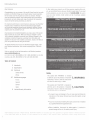 2
2
-
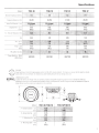 3
3
-
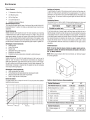 4
4
-
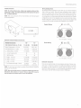 5
5
-
 6
6
-
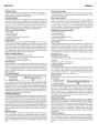 7
7
-
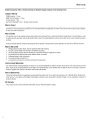 8
8
-
 9
9


Rockford Fosgate T1 S1-10 Manuale del proprietario
- Categoria
- Altoparlanti
- Tipo
- Manuale del proprietario
in altre lingue
Documenti correlati
-
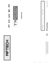 Rockford Fosgate T3-BMW-SUB Installation & Operation
-
Rockford Fosgate Punch HE RFP3412 Installation & Operation Manual
-
Rockford Fosgate T2S2-16 Installation & Operation
-
 Rockford Fosgate RM112D2 Manuale utente
-
 Rockford Fosgate Prime R1S4-10 Installation & Operation
-
Rockford Fosgate T1S1-12 Installation & Operation Manual
-
 Rockford Fosgate M1D4-12B Manuale utente
-
 Rockford Fosgate Element Ready M2D2-10IB Installation & Operation Manual
-
Rockford Fosgate RFD2110 Manuale utente
-
 Rockford Fosgate T112D2 Installation & Operation Manual


