
(1 8VHU0DQXDO
(OHFWULF6WRUDJH
'$ %UXJVDQYLVQLQJ
(OHFWULF6WRUDJH
12 %UXNVDQYLVQLQJ
(OHFWULF6WRUDJH
69 %UXNVDQYLVQLQJ
(OHFWULF6WRUDJH
), .¦\WW¸RKMH
(OHFWULF6WRUDJH
)5 1RWLFHGXWLOLVDWLRQ
(OHFWULF6WRUDJH
1/ *HEUXLNVDDQZLM]LQJ
(OHFWULF6WRUDJH
'( %HQXW]HULQIRUPDWLRQ
(OHFWULF6WRUDJH
,7 ,VWUX]LRQLSHUOൄXVR
(OHFWULF6WRUDJH
3/ ,QVWUXNFMDREVĄXJL
(OHFWULF6WRUDJH
*<(8(
*<(8(
*<(((
*<(((

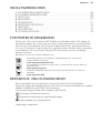
CONTENTS
1. SAFETY INFORMATION...........................................................................................3
2. SAFETY INSTRUCTIONS.......................................................................................... 5
3. INSTALLATION......................................................................................................... 6
4. CONTROL PANEL.....................................................................................................7
5. USAGE........................................................................................................................8
6. CARE AND CLEANING............................................................................................ 8
7. MAINTENANCE........................................................................................................ 9
8. TROUBLESHOOTING.............................................................................................11
9. TECHNICAL DATA..................................................................................................13
FOR PERFECT RESULTS
Thank you for choosing this AEG product. We have created it to give you
impeccable performance for many years, with innovative technologies that help
make life simpler features you might not find on ordinary appliances. Please
spend a few minutes reading to get the very best from it.
Visit our website for:
Get usage advice, brochures, trouble shooter, service information:
www.aeg.com/webselfservice
Register your product for better service:
www.registeraeg.com
Buy Accessories, Consumables and Original spare parts for your appliance:
www.aeg.com/shop
CUSTOMER CARE AND SERVICE
Always use original spare parts.
When contacting our Authorised Service Centre, ensure that you have the
following data available: Model, PNC, Serial Number.
The information can be found on the rating plate.
Warning / Caution-Safety information
General information and tips
Environmental information
Subject to change without notice.
ZZZDHJFRP

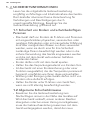
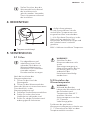
1. SAFETY INFORMATION
Before the installation and use of the appliance,
carefully read the supplied instructions. The
manufacturer is not responsible if an incorrect
installation and use causes injuries and damages. Always
keep the instructions with the appliance for future
reference.
1.1 Children and vulnerable people safety
• This appliance can be used by children aged from 8
years and above and persons with reduced physical,
sensory or mental capabilities or lack of experience
and knowledge only if they have been given
supervision or instruction concerning using the
appliance in a safe way and understanding the
hazards involved.
• Do not let children play with the appliance.
• Keep all packaging items away from children.
• If the appliance has a child safety device, or a function
that limits the temperature permanently, we
recommend you activate it.
• Cleaning and user maintenance shall not be made by
children without supervision.
• Children of less than 8 years should be kept away
unless continuously supervised.
1.2 General safety
• It is most important that this instruction book should
be retained with the appliance for future reference.
Should the appliance be sold or transferred to another
owner, or should you move to another house and
leave the appliance, always ensure that the book is
supplied with the appliance in order that the new
owner can get to know the functioning of the
appliance and the relevant warnings.
(1*/,6+

• Correct functioning of your appliance does not only
depend on product quality, but on correct installation
by a qualified professional.
• Never remove or damage stickers, warning labels or
nameplates attached to the appliance.
• A qualified technician carrying out the installation is
obliged to observe applicable national standards and
regulations concerning connection to the water
distribution system and the electric network. The
manufacturer is not responsible for any unprofessional
or incorrect installation.
• Check that the specifications written on the
appliance’s identification plate are the same as those
of the electrical power supply.
• This appliance is manufactured and tested in
accordance with valid regulations.
• The operating water pressure (minimum and
maximum) must be between 0,1 bar (0,01 MPa) and 10
bar (1,0 MPa).
• To prevent scalds while using the water heater, always
check the water temperature and adjust as needed
before use.
In the case of faults, a peak temperature of up
to 99 °C may briefly occur in the system.
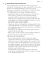
1.3 Special information
• When permanently connected to the power supply
using a dedicated junction box, the appliance must be
able to be isolated from the mains power supply by an
isolator that disconnects all poles with at least 3 mm
contact separation.
• The power cable may only be replaced (for example if
damaged) by a qualified contractor authorised by the
manufacturer, using an original spare part.
• Secure the appliance as described in chapter "3.3".
• Observe the maximum permissible pressure (see
chapter "9.4").
ZZZDHJFRP

• Drain the appliance as described in chapter "7.2".
• The appliance is pressurised. During the heat-up
process, expansion water will drip from the safety
valve.
• Regularly activate the safety valve to prevent it from
becoming blocked, e.g. by limescale deposits.
• Install a type-examination tested safety valve in the
cold water supply line. Depending on the supply
pressure, you may also need a pressure reducing
valve.
• Size the drain pipe so that water can drain off
unimpeded when the safety valve is fully opened.
• Fit the drain pipe of the safety valve with a constant
downward slope and in a room free from the risk of
frost.
• The safety valve drain must remain open to the
atmosphere.
2. SAFETY INSTRUCTIONS
2.1 Installation
• Obey the installation instruction
supplied with the appliance.
• Remove all the Packaging items.
• Do not install or use a damaged
appliance.
• Before first time starting up, check the
appliance for any damage incurred
during transport.
• Never remove or damage stickers,
warning labels or nameplates
attached to the appliance.
2.2 Water Connection
• Make sure not to cause damage to
the water hoses.
• The appliance is to be connected to
the water mains using suitable hose-
sets.
• Before you connect the appliance to
new pipes or pipes not used for a
long time, let the water flow until it is
clean.
• The first time you use the appliance,
make sure that there is no leakage.
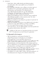
2.3 Electrical Connection
WARNING!
Risk of fire and electrical
shock.
To carry out all electrical
connection and installation
work in accordance with
relevant regulations.
• The appliance must be earthed.
•
Make sure that the electrical
information on the rating plate agrees
with the power supply. If not, contact
our Authorised Service Centre or an
electrician.
• Make sure the appliance is installed
correctly. Loose and incorrect
electricity mains cable or plug (if
applicable) can make the terminal
become too hot.
• Do not use multi-plug adapters and
extension cables.
• Make sure not to cause damage to
the mains plug (if applicable) or to the
mains cable. Contact our Authorised
(1*/,6+

Service Centre or an electrician to
change a damaged mains cable.
• The electrical installation must have
an isolation device which lets you
disconnect the appliance from the
mains at all poles. The isolation
device must have a contact opening
width of minimum 3 mm.
An appropriate socket or
adapter for the Schuko plug
should be used if necessary.
The water heater needs to
be connected to the
protective conductor.
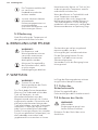
2.4 CE designation
The CE designation shows that the
appliance meets all essential
requirements according to the:
• Low Voltage Directive.
• Electromagnetic Compatibility
Directive.
• RoHS directive.
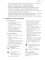
3. INSTALLATION
3.1 Standard delivery
The following are delivered with the
appliance:
• Wall mounting bracket.
• Two locking ring fitting G ½ x 15
(delivered only with GYE01016UE +
GYE01516UE).
3.2 Placement
The sealed unvented
(pressurised) appliance is
only suitable for undersink
installation. The appliance is
intended for heating cold
water and to supply one or
several draw-off points.
The appliance may only be installed with
pressure taps in conjunction with a type-
examination tested safety valve.
The type-examination tested safety valve
protects the appliance against
unacceptable excess pressure.
WARNING!
Do not install the appliance
in the following places:
• Outdoors.
• Areas that are cold and
freezing, the freezing
water may damage the
internal tank and pipes.
• Where water discharge is
not possible.
Ensure that the appliance is
freely accessible for
maintenance work.
Always install the appliance vertically and
near the draw-off point.
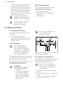
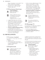
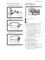
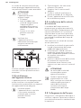
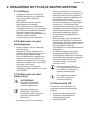
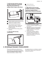
3.3 Appliance installation
The appliance is designed for installation
on a solid wall. Ensure the wall offers
adequate load bearing capacity.
Always install the appliance
vertically in a room free from
the risk of frost and near the
draw-off point.
1. Mark out the holes to be drilled on
the wall.
2. Drill the holes and insert suitable rawl
plugs.
3. Secure the wall mounting bracket
using suitable screws.
ZZZDHJFRP

4. Hang the appliance on the wall
mounting bracket.
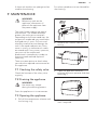
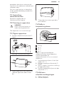
3.4 Safety valve installation
The water heaters are designed for a
maximum rated pressure of 1 MPa.
According to EN 60335-2-21 the safety
valve must prevent the water pressure to
exceed the maximum rated pressure of
the water heater from more than 0.1
MPa.
A type-examination tested safety valve is
required.
1. Install the safety valve in the cold
water supply line of the appliance.
2. Size the drain pipe so that water can
drain off unimpeded when the safety
valve is fully opened.
3. Fit the drain pipe of the safety valve
with a constant downward slope and
in a room free from the risk of frost.
WARNING!
The safety valve drain must
remain open to the
atmosphere.
If the supply pressure is
>0.48 MPa, install a pressure
reducing valve upstream of
the safety valve in the cold
water supply line.
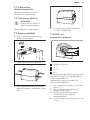
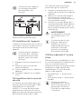
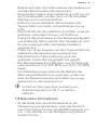
3.5 Water connection
Carry out all water connection and only
install pressure taps in conjunction with a
safety valve accordance with regulations.
Match up the colour coding on the water
connections of the tap and the
appliance:
• R.h. side blue = "Cold water inlet"
• L.h. side red = "Hot water outlet"
Ensure that the water
connections are not kinked
during installation. Prevent
any tensioning during
installation.
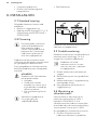
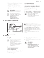
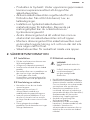
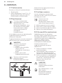
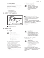
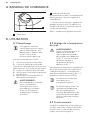
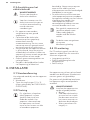
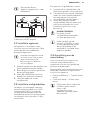
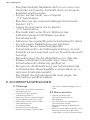
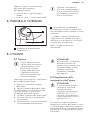
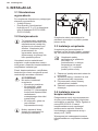
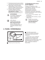
4. CONTROL PANEL
1
2
1
Temperature selector knob.
2
Heat-up indicator lamp.
Depending on the system, the actual
temperatures may vary from the set
value.
* = Cold. On this setting, the appliance is
protected from frost. The tap, water lines
and safety valve are not protected.
MAX = Highest selectable temperature.
(1*/,6+

5. USAGE
5.1 Filling
This sealed unvented
(pressurised) appliance is
intended for heating
domestic hot water. The
appliance can supply one or
more draw-off points.
Once the water heater has been
installed:
1. Open the water source valve.
2. Open the hot tap.
When the water starts to run through it
with constant flow, then the water heater
will be full.
3. Close the hot taps
4. Make sure there are no leaks in the
installation.
5. Check that the safety valve is working
correctly.
WARNING!
Do not connect the water
heater to the main power
supply without being sure
that it is full of water,
otherwise the heating
element may be damaged.
5.2 Adjusting water
temperature
WARNING!
During operation, the tap
and safety valve can reach
temperatures in excess of 60
°C. There is a risk of scalding
at outlet temperatures in
excess of 43 °C.
You can set any required temperature of
outlet water at the temperature selector,
it's steplessly variable from 11°C (frost
protection) to MAX.
The temperature selector
should only be removed by a
qualified contractor.
Subject to season, varying
cold water temperatures can
result in different maximum
mixed water and outlet
volumes.
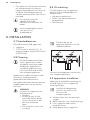
5.3 Operating
After the temperature had been adjusted
to the desired value, the heating element
will heat up the water inside the tank
until the water temperature reaches to
the setting value, then heater will go to
OFF state.
After the water inside the tank gets
cooler, and the temperature will be lower
than the setting temperature, the
heating process will start working again
and heat the water inside the tank. The
operation will repeat continuously in
automatic manner as long as the
electrical source connected to the water
heater.
6. CARE AND CLEANING
WARNING!
All the repair and
maintenance must be
carried out by customer
service authorized
technicians.
Regularly activate the safety
valve to prevent it from
becoming blocked, e.g. by
limescale deposits.
Appliance malfunctions should be
repaired immediately to keep the
performance of it.
ZZZDHJFRP

A clean soft cloth or wet sponge can be
used for the cleaning.
Dis-solvent products are not allowed for
the cleaning.
7. MAINTENANCE
WARNING!
Before any work on the
appliance, disconnect all
poles of the appliance from
the power supply.
The water heater requires no special
maintenance. The anode rod helps
protect the tank against corrosion.
Depending on the water condition, the
magnesium anode rod may need to be
changed every 2 years. Galvanic and
electrolytic corrosion can damage the
tank if the anode rod worn out. Rusty
water is usually an indication of a worn
out anode rod. If rusty water is present,
you must call the authorized
professionals immediately in order to
examine anode rod and replace if
necessary.
There are some points to check when
you make the required maintenance for
this appliance.
7.1 Checking the safety valve
Check the function of the safety valve
regularly.
7.2 Draining the appliance
WARNING!
Hot water may escape
during the draining process.
Drain the appliance via its connectors.
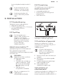
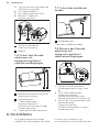
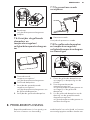
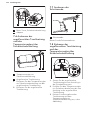
7.3 Opening the appliance
1. Pull off the temperature selector and
the limiting ring.
2. Remove the 4 screws from the
casing.
3. Open the appliance cover by
pivoting the cover upwards and then
removing it.
4. Remove the upper insulation semi-
shell if required.
(1*/,6+

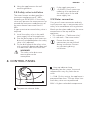
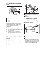
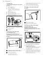
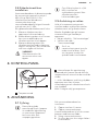
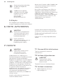
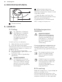
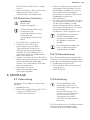
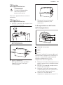
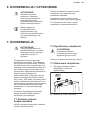
7.4 Setting the temperature
limit
1
2
3
4
1
Limiting ring
2
38 °C
3
49 °C
4
65 °C
Placing the limiting ring behind the
temperature selector allows you to limit
the setting range of the temperature
selector to a specific maximum
temperature.
1. Turn the temperature selector to
zero (fully clockwise to "*").
2. Pull off the temperature selector and
the limiting ring.
3. Push the limiting ring with the
required maximum setting onto the
appliance cover.
4. Install the temperature selector set to
zero ("*").
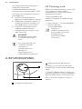
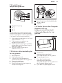
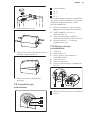
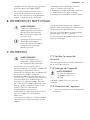
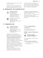
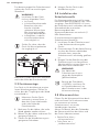
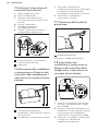
7.5 Activate high limit safety
cut-out
1. Open the appliance.
2. Pull off the adaptor.
3. Press the reset button on the high
limit safety cut-out.
4. Fit the adaptor.
5. Close the appliance cover.
6. Fit the limiting ring and temperature
selector.
12
1
Reset button, high limit safety cut-
out
2
Adaptor
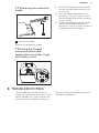
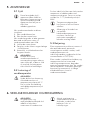
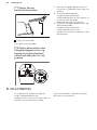
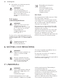
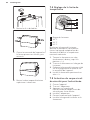
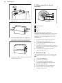
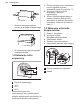
7.6 Removing the flanged
immersion heater and
temperature controller / high
limit safety cutout
12
1
Combined temperature controller /
high limit safety cut-out.
2
Flanged immersion heater.
1. Remove the combined temperature
controller / high limit safety cut-out
from the flanged immersion heater.
2. Remove the flanged immersion
heater.
ZZZDHJFRP

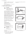
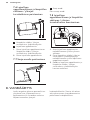
7.7 Removing the protective
anode
1
1
Protective anode
Remove the protective anode.
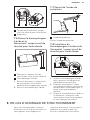
7.8 Fitting the flanged
immersion heater and
temperature controller / high
limit safety cutout
1. Insert the flanged immersion heater
into the cylinder aperture well as far
as it will go.
2. Push the combined temperature
controller / high limit safety cut-out
into the flanged immersion heater as
far as it will go.
3. Align the flanged immersion heater
and the combined temperature
controller / high limit safety cut-out in
accordance with the diagram.
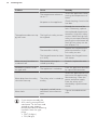
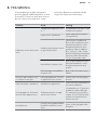
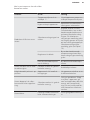
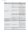
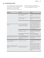
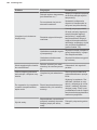
8. TROUBLESHOOTING
Certain problems are due to lack of
simple maintenance or oversights, which
can be solved easily without calling the
service technicians, before contacting
the local service centre please carry out
the check listed below.
(1*/,6+

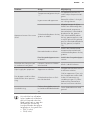
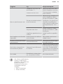
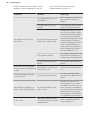
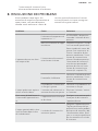
Problem Cause Remedy
The appliance does not sup-
ply hot water.
The temperature selector is
set to "*".
Switch the appliance ON by
turning the temperature se-
lector.
No power at the appliance.
Check the plug / fuses in the
fuse box.
The high limit safety cut-out
has tripped.
Remedy the cause of the
fault. If necessary, replace
the combined temperature
controller / high limit safety
cut-out. Make the high limit
safety cut-out operational by
pressing the reset button on
the high limit safety cut-out
(see chapter 7.5).
The controller is faulty.
Replace the combined tem-
perature controller / high
limit safety cut-out.
The flanged immersion heat-
er is faulty.
Replace the flanged immer-
sion heater.
Water can only be drawn at
a reduced rate.
The aerator in the tap is
scaled up or dirty.
Descale / replace the aera-
tor.
Loud boiling noises inside
the appliance.
The appliance is scaled up.
Have the appliance descaled
by a qualified contractor.
Water drips from the safety
valve after heat-up.
The safety valve is scaled up
or dirty.
Switch the appliance off. De-
pressurise the appliance by
disconnecting it from the
power and water supply.
Have the safety valve
checked by a qualified con-
tractor.
Water leaks.
Improperly sealed, hot or
cold water source connec-
tions.
Tighten threaded connec-
tions.
If you cannot remedy the
fault, notify your qualified
contractor. To facilitate and
speed up your enquiry,
please provide the following
numbers from the type
plate :
• PNC (9 digits)
• SN (8 digits)
ZZZDHJFRP

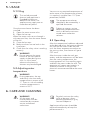
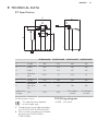
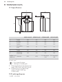
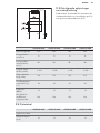
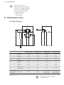
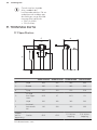
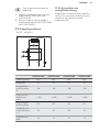
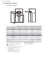
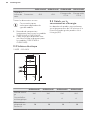
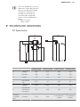
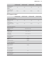
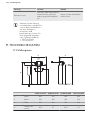
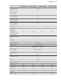
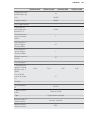
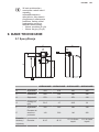
9. TECHNICAL DATA
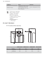
9.1 Specification
A
80
mm
100
mm
F
C
G
H
E
2
1
GYE01016UE GYE01516UE GYE01016EE GYE01516EE
H Height 454 476 430 452
C Width 280 320 280 320
A Depth 270 318 270 318
G
Top clear-
ance
50.5 47 26.5 23
F Height 320 342 320 342
E
Horizontal
hole spac-
ing
140 200 140 200
Inlet & Out-
let Pipe
Size Ø15 Ø15
G ½ A Male
thread
G ½ A Male
thread
All dimensions in mm
This specifications depend
on the model type
1. Compression fittings (delivered only
with GYE01516UE & GYE01016UE).
2. Electric cable (available with Schuko
plug only for GYE01516EE &
GYE01016EE).
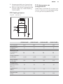
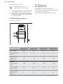
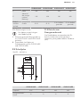
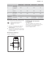
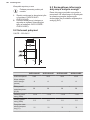
9.2 Wiring diagram
1/N/PE ~ 220-240 V
(1*/,6+

L
AB
NPE
12
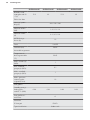
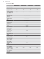
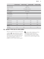
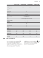
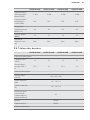
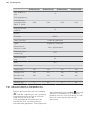
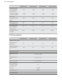
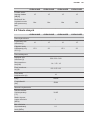
9.3 Details on energy
consumption
Product data complies with EU
regulations relating to the Directive on
the ecodesign of energy related
products (ErP).
GYE01016UE GYE01516UE GYE01016EE GYE01516EE
Load profile XXS XXS XXS XXS
Energy efficien-
cy class
AAAA
Energy conver-
sion efficiency
(%)
Daily power
consumption
(kWh)
2.42 2.42 2.42 2.42
Annual power
consumption
(kWh)
515 515 515 515
Default temper-
ature setting
(°C)
55 55 55 55
Sound power
level (dB(A))
15 15 15 15
Off-peak peri-
ods possible
No No No No
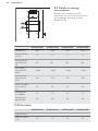
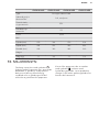
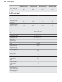
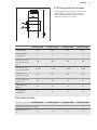
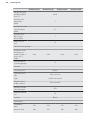
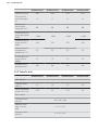
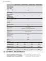
9.4 Data table
GYE01016UE GYE01516UE GYE01016EE GYE01516EE
Hydraulic data
Nominal capaci-
ty (L)
10 15 10 15
ZZZDHJFRP

GYE01016UE GYE01516UE GYE01016EE GYE01516EE
Mixed water vol-
ume at 40 °C (L)
15.3 23 15.3 23
Electrical data
Rated voltage
(V)
220 / 230 / 240
Rated output
(kW)
1.4 / 1.5 / 1.6
Rated current
(A)
6.2 / 6.5 / 6.8
MCB/fuse rating
(A)
10
Phases 1/N/PE
Frequency (Hz) 50/60
Application limits
Temperature
setting range
(°C)
30-65
Max. permissi-
ble pressure
(MPa)
1
Min. water inlet
pressure (MPa)
0.1
Max. water inlet
pressure (MPa)
1
Max. flow rate
(L/min)
10
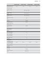
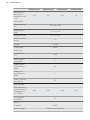
Energy data
Standby energy
consumption/24
h at 65 °C (kWh)
0.48 0.49 0.48 0.49
Energy efficien-
cy class
A
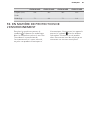
Versions
IP rating IP24 D
Type of installa-
tion
Undersink
(1*/,6+

GYE01016UE GYE01516UE GYE01016EE GYE01516EE
Type Sealed unvented
Internal cylinder
material
Steel, enamelled
Thermal insula-
tion material
EPS
Casing material PS
Colour White
Dimensions
Depth (mm) 270 318 270 318
Height (mm) 454 476 430 452
Width (mm) 280 320 280 320
Weights
Weight (kg) 7.1 8.6 7.1 8.6
10. ENVIRONMENTAL CONCERNS
Recycle the materials with the symbol .
Put the packaging in applicable
containers to recycle it. Help protect the
environment and human health and to
recycle waste of electrical and electronic
appliances. Do not dispose appliances
marked with the symbol
with the
household waste. Return the product to
your local recycling facility or contact
your municipal office.
ZZZDHJFRP

INDHOLDSFORTEGNELSE
1. OM SIKKERHED...................................................................................................... 18
2. SIKKERHEDSANVISNINGER.................................................................................. 20
3. INSTALLATION....................................................................................................... 21
4. BETJENINGSPANEL...............................................................................................22
5. ANVENDELSE..........................................................................................................23
6. VEDLIGEHOLDELSE OG RENGØRING................................................................23
7. VEDLIGEHOLDELSE............................................................................................... 24
8. FEJLFINDING.......................................................................................................... 26
9. TEKNISKE DATA..................................................................................................... 28
FOR PERFEKTE RESULTATER
Tak fordi du valgte dette produkt fra AEG. Vi har skabt det, så du kan nyde en
uovertruffen funktionsevne i mange år med nyskabende teknologi, der gør livet
lettere – funktioner, som du ikke finder i almindelige apparater. Brug et par
minutter på at læse mere – så du kan få det bedste ud af det.
Besøg vores websted for at:
Få rådgivning, brochurer, fejlfinding, serviceinformation:
www.aeg.com/webselfservice
Registrere dit produkt for bedre service:
www.registeraeg.com
Købe tilbehør, forbrugsvarer og originale reservedele til dit apparat:
www.aeg.com/shop
KUNDEPLEJE OG SERVICE
Brug altid originale reservedele.
Sørg for at have følgende data tilgængelig, når du kontakter vores autoriserede
servicecenter: Model, PNC, serienummer.
Du finder oplysningerne på maskinens typeskilt.
Advarsel/Forsigtig-Sikkerhedsanvisninger
Generelle oplysninger og gode råd
Miljøoplysninger
Ret til ændringer uden varsel forbeholdes.
'$16.

1. OM SIKKERHED
Læs brugsanvisningen grundigt, før apparatet installeres
og tages i brug. Producenten kan ikke drages til ansvar,
hvis apparatet installeres forkert og anvendelsen
forårsager skade. Opbevar altid brugsanvisningen
sammen med apparatet til eventuel fremtidig brug.
1.1 Sikkerhed for børn og andre udsatte personer
• Apparatet kan kun bruges af børn fra 8 år og opefter
samt af personer med nedsat fysisk, sensorisk eller
psykisk funktionsevne, eller som mangler den
nødvendige erfaring eller viden, hvis de er under
opsyn eller er blevet instrueret i at bruge apparatet på
en sikker måde samt forstår de medfølgende farer.
• Børn må ikke lege med apparatet.
• Opbevar al emballagen utilgængeligt for børn.
• Hvis apparatet har en børnesikring eller en funktion,
der begrænser temperaturen permanent, anbefales
det, at du aktiverer den.
• Rengøring og vedligeholdelse må ikke udføres af børn
uden overvågning.
• Børn på under 8 år skal holdes på afstand, med
mindre de overvåges konstant.
1.2 Generelt om sikkerhed
• Det er meget vigtigt, at brugsanvisningen til apparatet
gemmes, så den kan bruges til at slå op i. Hvis
apparatet skifter ejer – enten fordi det sælges/
overdrages til en anden, eller fordi ejendommen
sælges, og apparatet bliver stående – skal
vejledningen altid følge med apparatet, så den nye
ejer kan sætte sig ind i, hvordan det virker, og er
bekendt med de tilhørende advarsler.
• Korrekt drift af dit apparat afhænger ikke kun af
produktkvalitet, men af korrekt installation udført af en
kvalificeret faguddannet person.
ZZZDHJFRP

• Du må aldrig fjerne eller beskadige etiketter,
advarselsmærker eller typeskilte, der sidder på
apparatet.
• En kvalificeret tekniker, der udfører installationen, har
pligt til at overholde gældende nationale standarder
og bestemmelser vedrørende tilslutningen til
vandforsyningssystemet og elnettet. Producenten har
ikke ansvaret for ufaglært eller forkert installation.
• Kontrollér, at specifikationerne på apparatets
identifikationsskilt er de samme som for
strømforsyningen.
• Dette apparat er fremstillet og testet i
overensstemmelse med gyldige bestemmelser.
• Vandtrykket (minimum og maksimum) skal være
mellem 0,1 bar (0,01 MPa) og 10 bar (1,0 MPa).
• Med henblik på at forhindre skoldninger under brug af
vandvarmeenheden skal du altid kontrollere
vandtemperaturen og justere efter behov inden brug.
I tilfælde af fejl kan der kortvarigt forekomme en
spidstemperatur på 99 °C i systemet.
1.3 Specielle oplysninger
• Når apparatet er sluttet permanent til
strømforsyningen ved hjælp af en særlig samledåse,
skal det kunne isoleres fra netstrømforsyningen med
en isolator, der frakobler alle poler med mindst 3 mm
kontaktadskillelse.
• Strømkablet må kun udskiftes (f.eks. hvis beskadiget)
af en kvalificeret tekniker, der er autoriseret af
fabrikanten, med brug af en original reservedel.
• Fastgør apparatet, som beskrevet i kapitel "3.3".
• Overhold det maksimalt tilladte tryk (se kapitel "9.4").
• Tøm apparatet, som beskrevet i kapitel "7.2".
• Apparatet er under tryk. Under
opvarmningsprocessen drypper der udvidelsesvand
fra sikkerhedsventilen.
'$16.

• Aktivér regelmæssigt sikkerhedsventilen for at
forhindre, at den bliver blokeret. f.eks. af
kalkaflejringer.
• Installér en typeafprøvningstestet sikkerhedsventil i
koldtvandsforsyningslinjen. Afhængigt af
forsyningstrykket kan det også være nødvendigt med
en trykreduktionsventil.
• Afløbsrøret skal dimensioneres, så vandet kan tømmes
uhindret, når sikkerhedsventilen er helt åben.
• Påmontér sikkerhedsventilens afløbsrør med en
konstant nedadrettet skråning og i et rum uden
frostrisiko.
• Sikkerhedsventilens afløb skal forblive åbent ud til
luften.
2. SIKKERHEDSANVISNINGER
2.1 Installation
• Følg installationsvejledningen, der
følger med apparatet.
• Fjern al emballagen.
• Undlad at installere eller bruge et
beskadiget apparat.
• Efterse apparatet for eventuelle
transportskader, inden det startes for
første gang.
• Du må aldrig fjerne eller beskadige
etiketter, advarselsmærker eller
typeskilte, der sidder på apparatet.
2.2 Tilslutning, vand
• Pas på du ikke beskadiger
vandslangerne.
• Apparatet skal sluttes til
vandledningsnettet ved hjælp af
egnede slangesæt.
• Inden du tilslutter apparatet til nye rør
eller rør, som ikke har været i brug i
lang tid, skal du lade vandet løbe,
indtil det bliver klart.
• Kontrollér, at der ikke er nogen
utætheder, første gang du bruger
apparatet.
2.3 Tilslutning, el
ADVARSEL!
Risiko for brand og elektrisk
stød.
De relevante bestemmelser
skal overholdes under alt el-
og installationsarbejde.
• Apparatet skal tilsluttes strøm m/jord,
jvf. Stærkstrømsreglementet.
• Sørg for, at de elektriske data på
typeskiltet svarer til strømforsyningen.
Ellers skal du kontakte vores
autoriserede servicecenter eller en
elektriker.
• Sørg for, at apparatet installeres
korrekt. En løs eller forkert netledning
eller stik (hvis relevant) kan gøre
terminalen for varm.
• Brug ikke multistik-adaptere og
forlængerledninger.
• Pas på, du ikke beskadiger netstikket
(hvis relevant) eller ledningen. Kontakt
vores autoriserede servicecenter eller
en elektriker, hvis en beskadiget
ledning skal udskiftes.
• Apparatets installation skal udføres
med et isolationsudstyr, så
forbindelsen til lysnettet kan afbrydes
på alle poler. Isolationsudstyret skal
ZZZDHJFRP
La pagina si sta caricando...
La pagina si sta caricando...
La pagina si sta caricando...
La pagina si sta caricando...
La pagina si sta caricando...
La pagina si sta caricando...
La pagina si sta caricando...
La pagina si sta caricando...
La pagina si sta caricando...
La pagina si sta caricando...
La pagina si sta caricando...
La pagina si sta caricando...
La pagina si sta caricando...
La pagina si sta caricando...
La pagina si sta caricando...
La pagina si sta caricando...
La pagina si sta caricando...
La pagina si sta caricando...
La pagina si sta caricando...
La pagina si sta caricando...
La pagina si sta caricando...
La pagina si sta caricando...
La pagina si sta caricando...
La pagina si sta caricando...
La pagina si sta caricando...
La pagina si sta caricando...
La pagina si sta caricando...
La pagina si sta caricando...
La pagina si sta caricando...
La pagina si sta caricando...
La pagina si sta caricando...
La pagina si sta caricando...
La pagina si sta caricando...
La pagina si sta caricando...
La pagina si sta caricando...
La pagina si sta caricando...
La pagina si sta caricando...
La pagina si sta caricando...
La pagina si sta caricando...
La pagina si sta caricando...
La pagina si sta caricando...
La pagina si sta caricando...
La pagina si sta caricando...
La pagina si sta caricando...
La pagina si sta caricando...
La pagina si sta caricando...
La pagina si sta caricando...
La pagina si sta caricando...
La pagina si sta caricando...
La pagina si sta caricando...
La pagina si sta caricando...
La pagina si sta caricando...
La pagina si sta caricando...
La pagina si sta caricando...
La pagina si sta caricando...
La pagina si sta caricando...
La pagina si sta caricando...
La pagina si sta caricando...
La pagina si sta caricando...
La pagina si sta caricando...
La pagina si sta caricando...
La pagina si sta caricando...
La pagina si sta caricando...
La pagina si sta caricando...
La pagina si sta caricando...
La pagina si sta caricando...
La pagina si sta caricando...
La pagina si sta caricando...
La pagina si sta caricando...
La pagina si sta caricando...
La pagina si sta caricando...
La pagina si sta caricando...
La pagina si sta caricando...
La pagina si sta caricando...
La pagina si sta caricando...
La pagina si sta caricando...
La pagina si sta caricando...
La pagina si sta caricando...
La pagina si sta caricando...
La pagina si sta caricando...
La pagina si sta caricando...
La pagina si sta caricando...
La pagina si sta caricando...
La pagina si sta caricando...
La pagina si sta caricando...
La pagina si sta caricando...
La pagina si sta caricando...
La pagina si sta caricando...
La pagina si sta caricando...
La pagina si sta caricando...
La pagina si sta caricando...
La pagina si sta caricando...
La pagina si sta caricando...
La pagina si sta caricando...
La pagina si sta caricando...
La pagina si sta caricando...
La pagina si sta caricando...
La pagina si sta caricando...
La pagina si sta caricando...
La pagina si sta caricando...
La pagina si sta caricando...
La pagina si sta caricando...
La pagina si sta caricando...
La pagina si sta caricando...
La pagina si sta caricando...
La pagina si sta caricando...
La pagina si sta caricando...
La pagina si sta caricando...
La pagina si sta caricando...
La pagina si sta caricando...
La pagina si sta caricando...
La pagina si sta caricando...
La pagina si sta caricando...
La pagina si sta caricando...
La pagina si sta caricando...
La pagina si sta caricando...
La pagina si sta caricando...
La pagina si sta caricando...
La pagina si sta caricando...
La pagina si sta caricando...
La pagina si sta caricando...
La pagina si sta caricando...
La pagina si sta caricando...
La pagina si sta caricando...
La pagina si sta caricando...
La pagina si sta caricando...
La pagina si sta caricando...
La pagina si sta caricando...
La pagina si sta caricando...
La pagina si sta caricando...
La pagina si sta caricando...
La pagina si sta caricando...
La pagina si sta caricando...
La pagina si sta caricando...
La pagina si sta caricando...
La pagina si sta caricando...
-
 1
1
-
 2
2
-
 3
3
-
 4
4
-
 5
5
-
 6
6
-
 7
7
-
 8
8
-
 9
9
-
 10
10
-
 11
11
-
 12
12
-
 13
13
-
 14
14
-
 15
15
-
 16
16
-
 17
17
-
 18
18
-
 19
19
-
 20
20
-
 21
21
-
 22
22
-
 23
23
-
 24
24
-
 25
25
-
 26
26
-
 27
27
-
 28
28
-
 29
29
-
 30
30
-
 31
31
-
 32
32
-
 33
33
-
 34
34
-
 35
35
-
 36
36
-
 37
37
-
 38
38
-
 39
39
-
 40
40
-
 41
41
-
 42
42
-
 43
43
-
 44
44
-
 45
45
-
 46
46
-
 47
47
-
 48
48
-
 49
49
-
 50
50
-
 51
51
-
 52
52
-
 53
53
-
 54
54
-
 55
55
-
 56
56
-
 57
57
-
 58
58
-
 59
59
-
 60
60
-
 61
61
-
 62
62
-
 63
63
-
 64
64
-
 65
65
-
 66
66
-
 67
67
-
 68
68
-
 69
69
-
 70
70
-
 71
71
-
 72
72
-
 73
73
-
 74
74
-
 75
75
-
 76
76
-
 77
77
-
 78
78
-
 79
79
-
 80
80
-
 81
81
-
 82
82
-
 83
83
-
 84
84
-
 85
85
-
 86
86
-
 87
87
-
 88
88
-
 89
89
-
 90
90
-
 91
91
-
 92
92
-
 93
93
-
 94
94
-
 95
95
-
 96
96
-
 97
97
-
 98
98
-
 99
99
-
 100
100
-
 101
101
-
 102
102
-
 103
103
-
 104
104
-
 105
105
-
 106
106
-
 107
107
-
 108
108
-
 109
109
-
 110
110
-
 111
111
-
 112
112
-
 113
113
-
 114
114
-
 115
115
-
 116
116
-
 117
117
-
 118
118
-
 119
119
-
 120
120
-
 121
121
-
 122
122
-
 123
123
-
 124
124
-
 125
125
-
 126
126
-
 127
127
-
 128
128
-
 129
129
-
 130
130
-
 131
131
-
 132
132
-
 133
133
-
 134
134
-
 135
135
-
 136
136
-
 137
137
-
 138
138
-
 139
139
-
 140
140
-
 141
141
-
 142
142
-
 143
143
-
 144
144
-
 145
145
-
 146
146
-
 147
147
-
 148
148
-
 149
149
-
 150
150
-
 151
151
-
 152
152
-
 153
153
-
 154
154
-
 155
155
-
 156
156


AEG GYE01016EE Manuale utente
- Tipo
- Manuale utente
- Questo manuale è adatto anche per
in altre lingue
- français: AEG GYE01016EE Manuel utilisateur
- Deutsch: AEG GYE01016EE Benutzerhandbuch
- Nederlands: AEG GYE01016EE Handleiding
- dansk: AEG GYE01016EE Brugermanual
- svenska: AEG GYE01016EE Användarmanual
Documenti correlati
Altri documenti
-
Electrolux EYE030S1WE Manuale utente
-
AE EHT 120I Operating And Mounting Instructions Manual
-
STIEBEL ELTRON SBB 751-1001 Operation Instruction
-
Austria Email SISS 750 Operating And Mounting Instructions Manual
-
-
-
Hitachi DHWT300E-2.5H1E Istruzioni per l'uso
-
Panasonic PAWDHWM300ZE Istruzioni per l'uso
-
Rancilio EPOCA E Use and Maintenance Manual
-