VADDIO 999-6120-000W Manuale del proprietario
- Categoria
- Apparecchiature musicali supplementari
- Tipo
- Manuale del proprietario

Before operating this product, please read the instructions carefully and save this manual for future use.
Installation Instructions provided
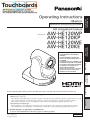
Operating Instructions
<Basics>
HD Integrated Camera
Model No.
VQT3U65
FJ1111MS0 -FJ
Printed in Japan
ENGLISH
How the Operating Instructions are configured
<Basics> (this manual):
This <Basics> describes the procedure for basic operation and installation. Before installing this unit, be
sure to take the time to read through <Basics> to ensure that the unit will be installed correctly.
This manual <Basics> is also contained as a PDF file on the CD-ROM supplied with the unit.
<Operations and Settings>:
The <Operations and Settings> describes how to operate the unit and how to establish its settings.
The <Operations and Settings> is contained as a PDF file on the CD-ROM supplied with the unit.
Adobe® Reader® is required to read PDF files.
It can be downloaded from the home page of Adobe Systems.
Die Bedienungsanleitung in Deutsch
ist als PDF-Datei in der CD-ROM
enthalten.
Le mode d’emploi en français est
fourni sous forme de fichier PDF sur
le CD-ROM.
Le istruzioni per l’uso in italiano sono
contenute in un file PDF sul CD-ROM.
Las instrucciones de funcionamiento
en español se encuentran en un
archivo PDF del CD-ROM.
Документ Инструкция по эксплуатации
на русском языке находится в виде
PDF-файла на диске CD-ROM.
Before useParts and
their functions
PreparationReference Operating
Instructions Installation
Instructions

2
ENGLISH
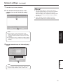
How to open the operating instruction manual PDF
files
Discontinue installation if the installation screen of the
software opens as a result of inserting the CD-ROM.
When [INDEX.pdf] on the CD-ROM is opened, a list of the
operating instruction manuals will be displayed.
Click on the document name of the manual to be opened.
Adobe® Reader® is required to read PDF files.
It can be downloaded from the home page of Adobe
Systems.
DEUTSCH
Öffnen der PDF-Dateien der Bedienungsanleitung
Brechen Sie die Installation ab, falls beim Einlegen der
CD-ROM der Installationsbildschirm der Software
erscheint.
Wenn [INDEX.pdf] auf der CD-ROM geöffnet wird,
erscheint eine Liste der Bedienungsanleitungen.
Klicken Sie auf den Dokumentennamen der zu öffnenden
Anleitung.
Zum Lesen der PDF-Dateien benötigen Sie Adobe®
Reader®.
Dieses Programm kann von der Homepage von Adobe
Systems heruntergeladen werden.
FRANÇAIS
Comment ouvrir les fichiers PDF des manuels du
mode d’emploi
Arrêter l’installation si l’écran d’installation du logiciel
s’ouvre quand le CD-ROM est inséré.
Quand [INDEX.pdf] sur le CD-ROM s’ouvre, la liste des
manuels du mode d’emploi s’affiche.
Cliquer sur le nom du document correspondant au manuel
à consulter.
Adobe® Reader® est nécessaire pour lire les fichiers
PDF.
Ce logiciel peut être téléchargé depuis la page d’accueil
d’Adobe Systems.
ITALIANO
Come aprire i file dei manuali di istruzioni per l’uso
Se inserendo il CD-ROM si apre la schermata di
installazione del software, interrompere l’installazione.
Aprendo [INDEX.pdf] sul CD-ROM, viene visualizzato un
elenco di manuali di istruzioni per l’uso.
Fare clic sul nome del documento corrispondente al
manuale da aprire.
Per leggere i file PDF è necessario Adobe® Reader®.
Il programma può essere scaricato dal sito Web di Adobe
Systems.
ESPAÑOL
Modo de abrir los archivos PDF que contienen el
manual de las instrucciones de funcionamiento
Interrumpa la instalación si la pantalla de instalación del
software se abre como resultado de insertar el CD-ROM.
Cuando se abra [INDEX.pdf] en el CD-ROM se
visualizará una lista de los manuales de instrucciones de
funcionamiento.
Haga clic en el nombre de documento del manual que va
a abrir.
Para leer los archivos PDF se necesita el programa
Adobe® Reader®.
Este programa se puede descargar de la página inicial de
Adobe Systems.
РУССКИЙ
Как открыть PDF-файлы инструкции по
эксплуатации
Прекратите установку, если в результате загрузки
диска CD-ROM появилось окно установки
программного обеспечения.
При открытии файла [INDEX.pdf] на диске CD-ROM
будет отображен список инструкций по эксплуатации.
Щелкните название документа руководства, чтобы
открыть его.
Для чтения PDF-файлов потребуется Adobe®
Reader®.
Данное программное обеспечение можно скачать с
домашней страницы Adobe Systems.

3
Trademarks and registered trademarks
Microsoft, Windows, Windows Vista, Windows 7 and
Internet Explorer are either registered trademarks or
trademarks of Microsoft Corporation in the United States
and other countries.
Intel and Intel Core are trademarks or registered
trademarks of Intel Corporation in the United States and
other countries.
Adobe and Reader are either registered trademarks or
trademarks of Adobe Systems Incorporated in the United
States and/or other countries.
HDMI, the HDMI logo and High-Definition Multimedia
Interface are the trademarks or registered trademarks
of HDMI Licensing, LLC in the United States and other
countries.
Other names of companies and products contained
in these Operating Instructions may be trademarks or
registered trademarks of their respective owners.
About copyright and licence
Distributing, copying, disassembling, reverse compiling,
reverse engineering, and also exporting in violation of export
laws of the software provided with this unit are expressly
prohibited.
Abbreviations
The following abbreviations are used in this manual.
Microsoft® Windows® 7 Professional SP1 32/64-bit is
abbreviated to “Windows 7”.
Microsoft® Windows Vista® Business SP2 32-bit is
abbreviated to “Windows Vista”.
Microsoft® Windows® XP Professional SP3 and Microsoft®
Windows® XP Home Edition SP3 are abbreviated to
“Windows XP”.
Windows® Internet Explorer® 8.0 and Windows® Internet
Explorer® 9.0 are abbreviated to “Internet Explorer”.
For the purposes of this manual, the model numbers of the
units are given as listed in the table below.
Model number
of unit Model number
given in manual
AW-HE120WP
AW-HE120
AW-HE120KP
AW-HE120WE
AW-HE120KE
AW-HS50N AW-HS50
AW-HS50E
AW-PS550N AW-PS550
AW-PS550E
AW-RP50N AW-RP50
AW-RP50E
AW-RP555N AW-RP555
AW-RP555L
AW-RP655N AW-RP655
AW-RP655L
Illustrations and screen displays featured in the
manual
What is shown in the manual’s illustrations and screen
displays may differ from how it is actually appears.

4
Contents
Installation Instructions
Operating Instructions
Read this first! ..................................................................5
Installation precautions ...................................................6
How to install and connect the unit ................................8
When using the WV-Q105 (optional accessory) ..........12
Changing the direction of the nameplate .....................13
Removing the camera ....................................................14
Stand-alone installation
(when the mount bracket is going to be used)........15
Stand-alone installation
(when the mount bracket is not going to be used)
...17
When installing the unit on a desktop ..........................17
When mounting the unit on a tripod .............................17
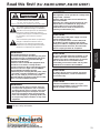
Read this first! (For AW-HE120WP, AW-HE120KP) ......23
Read this first! (For AW-HE120WE, AW-HE120KE) ......25
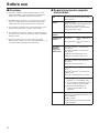
Before use .......................................................................28
Overview ......................................................................28
Required personal computer environment ...................28
Disclaimer of warranty..................................................29
Network security ..........................................................29
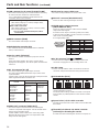
Characteristics ................................................................30
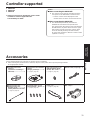
Controller supported ......................................................31
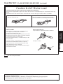
Accessories ....................................................................31
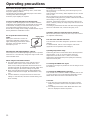
Operating precautions ...................................................32
Concerning the wireless remote control
(optional accessory) ..................................................34
Connections ....................................................................18
Connections with an HD monitor .................................18
Connections with a controller
(AW-RP655 or AW-RP555) ........................................19
System example 1 (Serial control) ...............................20
System example 2 (IP control) .....................................21
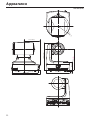
Appearance .....................................................................22
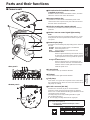
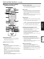
Parts and their functions ...............................................35
Camera unit .................................................................35
Wireless remote controller (optional accessory) ..........37
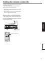
Setting the remote control IDs ......................................39
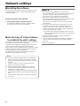
Network settings .............................................................40
Installing the software ..................................................40
Use the Easy IP Setup Software
to establish the unit’s settings ....................................40
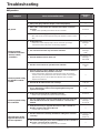
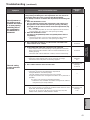
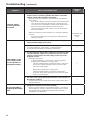
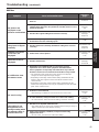
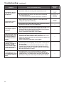
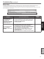
Troubleshooting ..............................................................42
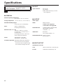
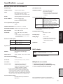
Specifications .................................................................48
Index ................................................................................50

5
Installation
Instructions
indicates safety information.
WARNING:
To prevent injury, this apparatus must be securely
attached to the floor/wall in accordance with the
installation instructions.
CAUTION:
This camera intended for use only with the Mount
Bracket enclosed with the unit and Panasonic
Direct Ceiling Mount Bracket, WV-Q105.
Use with other apparatus is capable of resulting
in instability causing possible injury.
WARNING:
Installation should only be performed by qualified
installation personnel.
Improper installation may result in the entire
apparatus falling down and causing injury.
Read this first!

6
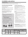
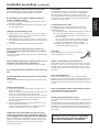
Installation precautions
To installation personnel
Read the Instructions thoroughly and then perform the operation correctly and safely.
Also, always read the “Read this first!” on page 5 of this manual as they contain important information.
After the installation, give this Instruction manual to the customer to save for future use.
Ensure that the installation work complies with the
technical standards governing electrical equipment.
This unit is for indoor use only.
It cannot be used outdoors.
Avoid installation in a location where the unit will be exposed
to direct sunlight for extended periods or near a cooling or
heating appliance.
Otherwise, deformation, discoloration, malfunctioning and/or
problems in operation may result. Operate the unit where it
will not be splashed or sprayed by water.
Use the unit with an installation where the unit is
suspended from an overhead surface or with a
stand-alone installation.
Do not use the unit on its side or tilted at an angle.
Be absolutely sure to use the four bracket mounting
screws (M4) for mounting the mount bracket.
These are supplied with the unit. Do not use wood
screws, nails, etc.
In the case of a concrete ceiling, secure the unit using
anchor bolts (for M4) or AY plug bolts (for M4).
Recommended clamping torque
M4: 1.47 N · m {15 kgf · cm}
The withdrawal strength of the mounting location for
each screw must be at least 294 N {30 kgf}.
When mounting the unit on a ceiling made of
plasterboard, for instance, if it is not strong enough
to support its weight, either reinforce the ceiling
adequately or use the WV-Q105 direct ceiling mount
bracket, which is sold separately.
When using a mount bracket which is sold separately,
read the handling instructions.
Do not hold the camera head while undertaking the
installation work. Doing so may cause malfunctioning.
OK NGOK NG
Desktop installation Hanging installation
Notes
AW-HE120
main unit Mounting conditions
Applicable mount bracket Mounting onto the ceiling
Mass Model No. Mass Mounting Recommended
screws No. of
screws Minimum withdrawal strength
(per screw)
Approx.
3.0 kg [6.61 lbs]
(Including
mount bracket)
Direct mount
(supplied
accessory)
Approx.
0.4 kg
[0.88 lbs] Hanging/Desktop M4 screws
(supplied
accessory) 4294 N {30 kgf}
Ensure that the mounting strength
can support a weight that is at least
five times the total mass of the
equipment, including the camera’s
main unit.
WV-Q105
(optional
accessory)
Approx.
0.15 kg
[0.33 lbs] For ceiling M4 screws
(supplied with the
WV-Q105) 4
Concerning the installation location
Install the unit in a stable location which will not be
susceptible to shaking. If the unit is installed in a location
which is susceptible to shaking, this will cause the unit’s
images to shake in turn.
Install the unit after conferring in detail with your dealer.
Install the unit on a ceiling that is strong enough (such as a
concrete ceiling).
If the unit is to be installed on a ceiling which is not strong
enough, reinforce the ceiling sufficiently first.
Do not install or use the unit in the following kinds of
locations.
On walls (where the unit would be installed sideways)
In locations (including places such as under the eaves of
a building) where the unit would be directly exposed to
rain or water
In locations such as kitchens where there are high
concentrations of steam and grease
In outdoor locations or hot places where the temperature
will exceed 40 °C (104 °F)
In cold locations where the temperature will drop below
0 °C (32 °F)
In locations where the humidity will exceed 85 %
In locations where chemicals are used such as near
swimming pools
At sea, in coastal areas or in locations where corrosive
gases are emitted
In locations where radiation, X-rays, or strong radio waves
or magnetic fields are generated
In locations where the unit would be subject to a great
deal of vibration such as on board a vehicle or ship (this
unit is not designed to be used in vehicles)
In locations where the temperature is subject to sudden
changes such as near the air outlet of an air conditioner or
near a door which allows the outside air to come in
What to avoid to ensure that the unit will perform stably
over a prolonged period
Using the unit for a prolonged period in a location with
high temperature and humidity levels will cause its parts to
deteriorate and shorten its service life.
Ensure that a cooling unit or heating unit will not blow any
air directly toward the installation location.

7
Installation
Instructions
Installation precautions (continued)
Before installation, always disconnect the power plug
When installing, always use the supplied components.
Do not disassemble or modify the wall mount adaptor.
Be absolutely sure to use the supplied brackets and
screws to install the camera.
Do not mount the unit by employing any methods other
than those specified.
Do not remodel the mounting bracket or mounting screws
provided with the unit.
Tightening up the mounting screws
Tighten up the screws and bolts securely to the degree
that is appropriate for each of the materials used in the
mounting location and structures.
After tightening up the screws and bolts, check that there
is no unsteadiness and that the parts have been tightened
securely.
Use the specified tools and tighten the screws firmly.
When the unit is no longer going to be used, do not
leave it lying around, but be absolutely sure to dispose
of it properly.
For details on how to remove the unit, refer to “Removing the
camera” (page 14).
When installing, transferring or disposing of the unit, be
absolutely sure to hold it by its pedestal area.
Problems may result if the camera head is held or rotated.
Do not attach a filter, hood, extender or other parts to the
unit.
Use the dedicated AC adaptor and power cable provided
with the unit.
Connect the AC adaptor and power cable to the power inlet
securely.
Installing the AC adaptor
Do not place the adaptor directly onto a ceiling panel or
other such surface.
Extreme danger is posed when water has collected on the
surface as a result of leaking rain, for instance.
Secure the adaptor firmly to the bottom or other surface of
a reinforcing member made of channel steel where dust
and other foreign matter will not accumulate.
(Refer to page 12.)
Secure the adaptor firmly so that there will be no chance
that it will fall off or fall down.
Secure it using a strength which can withstand the mass
(approx. 0.3 kg [0.66 lbs]) of the AC adaptor.
Install the accessory AC adaptor near the main power
outlet, and position it in such a way that its power plug
can be plugged into and unplugged from the outlet easily.
When connecting the AC adaptor to a power outlet on the
ceiling or on any other surface where dust may collect, wipe
off the dust on the power plug at periodic intervals as an
anti-tracking measure.
Power switch
This unit does not have a power switch. The power turns
on when its power plug is connected to a power outlet.
When the power is turned on, the pan, tilt, zoom and
focusing operations are performed. Before proceeding with
maintenance, be absolutely sure to disconnect the power
plug from the power outlet.
Connecting the power cable
Be absolutely sure to connect the power cable of the
AC adaptor through a circuit breaker using one of the
following methods.
(1) Connect the power cable through a power control unit.
(2) Connect the power cable to a circuit breaker in a
power distribution panel with a contact distance of
3.0 mm or more.
Use a circuit breaker which is capable of shutting
off all the poles of the main power supply with the
exception of the protective ground conductor.
(3) Install the AC adaptor near the power outlet, and
connect it through the power plug.
Grounding
Before using the unit, check that the grounding
wire has been fastened securely.
If there is a possibility of noise interference
Either wire the cables so that the power cable (ceiling light
cord) of AC 100 V or more, and the signal cable are placed
at least 1 meter (3.3 ft) apart. Alternatively run each cable
through its own metal conduit. (The metal conduits must be
grounded.)
Radio signal interference
If the unit is positioned near a TV or radio transmitting
antenna or a strong electrical field or magnetic field (such as
that generated by a motor, transformer or power lines), its
images may be distorted and/or the images may be affected
by noise.
When connecting the cables, ensure that the connector
areas will not be subject to any load.
Doing so may cause malfunctioning.
Allowing the generated heat to escape
This unit allows the heat generated inside to escape from its
surfaces.
Do not install the unit in a location where it will be surrounded
by walls or other surfaces and where heat will be trapped.
In addition, the heat is dissipated to the bottom panel which
will warm up over time: This is normal and not indicative of
any trouble.
Panasonic does not accept any responsibility
for accident or damage during installation if
procedure in this manual is not followed.

8
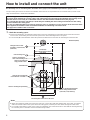
How to install and connect the unit
Be absolutely sure to read through the “Read this first!” (page 5) and “Installation precautions” (pages 6 to 7).
The procedure given here is for the kind of installation where the unit is suspended from an overhead surface, but the same
steps are followed for a stand-alone installation.
If the ceiling panel is not strong enough to bear the unit’s weight, use the kind of mount bracket that is supported
by anchor bolts between the concrete ceiling and ceiling panel. The unit supports the WV-Q105 direct ceiling mount
bracket which is used solely for combination cameras. Use this bracket to install the unit. (See page 12)
In a case like this, the holes (ø 60 mm [ø 2-3/8 inches]) for installing the direct ceiling mount bracket on the ceiling
must be drilled in the ceiling panel.
It is also recommended that you provide an inspection space or opening for access purposes in the area near where
the equipment is installed in order to facilitate installation and the wiring connections work.
See page 31 for details of the accessories.
1 Check the mounting space.
Refer to the illustration, and determine where the unit is to be installed and in which direction it should be mounted.
Factor in the unit mounting area and include space for the wires extending from its rear panel.
The asterisk () in the illustration marks the position and dimensions of the hole for mounting the mount bracket.
160 (6-5/16)
(Space for the wires from the
rear panel)
320 (12-19/32) or more
(Space for the wires)
90 (3-17/32)
88 (3-15/32) 136 (5-11/32)
108 (4-1/4)
()83.5
(3-9/32)
176 (6-15/16)
180 (7-3/32)
Hole for checking the positioning
The front panel of the unit on this side.
Unit: mm (inch)
Mount bracket
Hook for mounting the
drop-prevention wire
Unit mounting area
Through-hole for cable
ø 40 mm (ø 1-9/16 inches)
(reference)
() Holes for mounting the
mount bracket: ø 4.5 mm 4
Hole for mounting the
main unit mounting screw
Hole for installing the WV-Q105
direct ceiling mount bracket
[ø 60 mm (ø 2-3/8 inches)]
()46 (1-13/16)
Before proceeding to install and connect the main unit, connect the LAN cable, HDMI cable, VGA cable, AC adaptor
cable and coaxial cables in the space above the ceiling panel, and then pass the cables through the cable holes.
For a power outlet which is used on the ceiling, be absolutely sure to take measures to deal with the tracking that may
be caused by the accumulation of dust and other foreign matter.
Notes

9
Installation
Instructions
How to install and connect the unit (continued)
2 Mount the mount bracket onto the installation surface.
Use the bracket mounting screws (M4, bind-head: 10 mm long) supplied with the unit.
For proper clamping torque, securely attach the screws using the specified tools.
Screw diameter Clamping torque
M4 1.47 N · m {15 kgf · cm}
Bracket mounting screws 4 (supplied)
(M4, bind-head)
Use only the screws supplied with the unit. Do not use any other screws such as wood screws, nails, etc.
Note
3 Attach the drop-prevention wire.
Loop the circle part of the drop-prevention wire, which has been attached to the bottom panel of the unit, around the end
of the hook part of the mount bracket.
Pull the drop-prevention wire, and check that it has been attached securely to the hook.
End of hook
Drop-prevention
wire
Loop the circle part of
the drop-prevention wire
around the end of the hook
part of the mount bracket.
Pull the wire, and check that
it is securely attached to the
hook.
Do not do this work while holding the camera head since doing so may result in malfunctioning of the unit.
The drop-prevention wire is designed to be used for installation where the unit is suspended from an overhead
surface so do not subject it to the weight of units other than the unit.
Notes

10
How to install and connect the unit (continued)
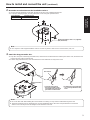
4 Mount the unit.
Align the position of the hole for checking the positioning with the status display lamp.
Align the holes on the camera main unit used to insert the bottom panel with the protrusions on the mount bracket used
for inserting the camera, push the bracket and camera firmly together, and rotate the main unit by about 20 degrees in
the direction of the arrow.
Secure the mount bracket to the unit using the main unit mounting screw (M3) as supplied.
Attach the mount bracket securely with the prescribed tool using the clamping torque below.
Be absolutely sure to verify that none of the screws are loose.
Screw diameter Clamping torque
M3 0.78 N · m {8 kgf · cm}
Main unit mounting screw (M3 screw)
(with flat washer, spring washer)
Status display lamp
Approx.
20°
On the camera
main unit: Holes
(3) used to insert
the bottom panel
On the mount
bracket: Protrusions
(3) used for
inserting the camera
Hole for checking
the positioning
Do not do this work while holding the camera head since doing so may result in malfunctioning of the unit.
Use only the screws supplied. Do not use any other screws.
Check that the unit has been mounted securely with no tilting or wobbling.
The unit must be secured without fail using the main unit mounting screw before any of the cables are connected.
Notes
5 Check the mounting.
Check out the following points.
• The main unit mounting screw must be mounted securely.
• The unit must not tilt, and it must be mounted exactly.
• The unit must be securely installed.
• The unit pedestal part must not rotate even when an attempt is made to turn it.

11
Installation
Instructions
How to install and connect the unit (continued)
6 Connect the rear panel connectors.
Anchor the AC adaptor cable in place using the cable clamp.
LAN cable
LAN cable
VGA cable
HDMI cable
Coaxial cable
AC adaptor cable
Square hole (one at either side)
Tab (one at either side)
Screw for cable cover (M3 screw)
(with flat washer, spring washer)
Cable clamp
Coaxial cable
Coaxial cable
How to secure the DC plug
Loosely secure the cable clamp.
Cable clamp
Loosely secure the cable clamp
in the area shown above.
Fasten the cable clamp.
Strap part
Take hold of the strap part, slide
the cable clamp until it stops
moving, and then secure it tightly.
7 Attach the cable cover.
Fit the two tabs on the cable cover into the square mounting hole at either side of the rear panel.
Secure the cable cover using the screw (M3 20 mm) provided.
Screw diameter Clamping torque
M3 0.78 N · m {8 kgf · cm}
Engage the tabs on the cable cover so they fit into place perfectly, and check that the cover is not rickety.
Note

12
How to install and connect the unit (continued)
When using the WV-Q105 (optional accessory)
It is recommended that you provide an inspection opening or other such space for access purposes in the area near where the
equipment is installed in order to facilitate installation and the wiring connections work.
Before mounting the mount bracket, check that the installation location is strong enough to withstand the total mass
(approx. 3.0 kg [6.61 lbs]) which will be exerted once the camera is mounted.
Use the mount bracket where the space between the ceiling panel and the concrete ceiling is at least 100 mm high.
The bracket can be mounted where the thickness of the ceiling panel ranges from 5 mm to 40 mm.
The drop-prevention wire (supplied with the WV-Q105) must be used when mounting the direct ceiling mount bracket.
Height above ceiling
panel: At least 100 mm The anchor bolts must not protrude
beneath the ceiling panel.
Ceiling panel (plasterboard, etc. with
a thickness from 5 mm to 40 mm)
Anchor bolts
Withdrawal strength: 294 N {30 kgf} or more
ø 60 mm
Concrete ceiling
1 Refer to the Operating Instructions of the WV-Q105 direct ceiling mount bracket, and attach the
WV-Q105 as well as the drop-prevention wire angle and drop-prevention wire supplied with the WV-Q105
to the anchor bolts.
Mounting the anchor bolts and direct ceiling mount bracket ()
This job is facilitated if the direct ceiling mount bracket is loosely secured to the ceiling panel in one place, and
the direct ceiling mount bracket and anchor bolts are vertically aligned before the nuts are tightened up.
2 First, remove the screws which were loosely fastened in step 1, and then align the camera mount
bracket of the AW-HE120 with the screw holes in the WV-Q105 direct ceiling mount bracket and mount it
in place.
Use the mounting screws (the M4-L60 Phillips head screws with adhesive) supplied with the WV-Q105 as the mounting
screws.
Fasten the AC adaptor securely to the bottom or other surface of the reinforcing member made of channel steel where
dust and other foreign matter will not accumulate.
Do not place the AC adaptor directly onto the ceiling panel or other such surface.
AW-HE120
Drop-prevention wire
angle (Supplied with
WV-Q105) Anchor bolts
Space above the ceiling
Direct ceiling mount bracket WV-Q105 (optional accessory)
Drop-prevention wire
(Supplied with WV-Q105) Plasterboard or other ceiling panel
Camera mount
bracket (Supplied
with AW-HE120)
Mounting screw 4
(Supplied with WV-Q105)
Channel steel
Secure the AC adaptor firmly to a
member made of channel steel.
( Ceiling
panel)
Inspection opening recommended
The installation and wiring connection
work is facilitated if an inspection
opening is provided for access purposes.
(): Fasten here using the nut.
3 Install the AW-HE120 camera by following the procedure starting with step 3 on page 9.

13
Installation
Instructions
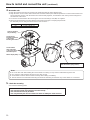
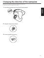
Changing the direction of the nameplate
When the unit is mounted on the ceiling, its nameplate will be upside down.
The direction of the unit’s nameplate can be changed.
1 Push in the part indicated by the arrow, and pull out the nameplate.
2 Change the direction of the nameplate.
3 Push the nameplate back into place.

14
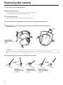
Removing the camera
1 Turn off the circuit breaker and power.
2 Remove the cable cover.
Remove the screw (M3) for the cable cover used to secure the cover.
Push the tab parts of the cover to disengage the cover.
3 Disconnect the cables.
Disconnect the power cable, video cable, and control cable, etc.
4 Remove the main unit mounting screw used to secure the unit and mount bracket.
5 Push the unit (). Turn it approximately 20 degrees away from the installed position (),
and remove it ().
Main unit mounting
screw (M3 screw)
(with flat washer, spring
washer)
Approx.
20°
Do not do this work while holding the camera head since doing so may result in malfunctioning of the unit.
Note
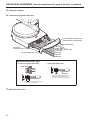
6 Disengage the drop-prevention wire from the mount bracket.
Pull the drop-
prevention wire in the
direction shown by the
arrow above.
Twist the wire, and
remove the wire loop
through the opening in
the hook.
Pull the wire in the
direction shown by the
arrow above, and simply
pull it out.

15
Installation
Instructions
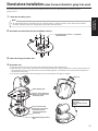
Stand-alone installation (when the mount bracket is going to be used)
The same steps are followed as for the kind of installation where the unit is suspended from an overhead surface
(pages 8 to 11).
1 Check the mounting space.
As with installing the unit suspended from an overhead surface, carefully check the space where the unit will be
mounted, and then decide if it is appropriate to install the unit in that space.
Note
2 Mount the mount bracket onto the installation surface.
Bracket mounting screws 4 (supplied)
(M4, bind-head)
3 Attach the drop-prevention wire.
4 Mount the unit.
Align the position of the hole for checking the positioning with the status display lamp.
Align the holes on the camera main unit used to insert the bottom panel with the protrusions on the mount bracket used
for inserting the camera, push the bracket and camera firmly together, and rotate the main unit by about 20 degrees in
the direction of the arrow.
Secure the mount bracket to the unit using the main unit mounting screw (M3) as supplied.
Main unit mounting screw
(M3 screw)
(with flat washer, spring
washer)
Status display lamp
On the camera main unit:
Holes (3) used to insert
the bottom panel
On the mount bracket:
Protrusions (3) used for
inserting the camera
Hole for checking the
positioning
Attach the drop-prevention
wire.
Approx. 20°

16
Stand-alone installation (when the mount bracket is going to be used)
(continued)
5 Check the mounting.
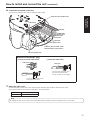
6 Connect the rear panel connectors.
Coaxial cable
Coaxial cable
Coaxial cable VGA cable
HDMI cable
AC adaptor cable
Square hole
(one at either side)
Tab (one at either side)
Screw for cable cover (M3 screw)
(with flat washer, spring washer)
LAN cable
LAN cable
How to secure the DC plug
Loosely secure the cable clamp.
Cable clamp
Loosely secure the cable clamp
in the area shown above.
Fasten the cable clamp.
Strap part
Take hold of the strap part, slide
the cable clamp until it stops
moving, and then secure it tightly.
7 Attach the cable cover.

17
Installation
Instructions
Stand-alone installation (when the mount bracket is not going to be used)
When installing the unit on a desktop
Place the unit flat on the surface.
Install the unit in a stable location which will not be susceptible to shaking. If the unit is installed in a location which is
susceptible to shaking, this will cause the unit’s images to shake in turn.
Take care not to allow the unit to fall or otherwise be damaged during installation.
When carrying the unit, do not hold it by its head.
Do not take hold of the camera head or rotate it. Doing so may cause malfunctioning.
Take care not to pull the connected cables. Doing so may cause the unit to fall and/or it may result in injury.
Notes
Ensure that the unit will not fall off.
OK NG
When mounting the unit on a tripod
Attach the tripod to the threaded holes for mounting the camera on the camera’s bottom panel.
Place the tripod on a completely flat and level surface.
Tighten the screws by hand to mount the tripod securely.
Use screw for mounting the tripod that satisfy the following standard.
Screw for mounting tripod
1/4-20UNC, ISO1222 (6.35 mm)
4.5 mm to 6 mm
(0.18 inches to 0.24 inches)
Do not install the unit where people will be passing back and forth.
When using the unit mounted on a tripod, do not put the tripod high above the floor level.
Mount the unit securely so there is no looseness. Looseness may cause the unit to fall off and/or result in injuries.
When the unit is going to be used for a prolonged period of time, take steps to ensure that the unit will not topple or fall
over and that it will not fall off or fall down. After using the unit, restore the installation location to its original state without
delay.
Notes

18
Connections
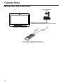
Connections with an HD monitor
HD monitor
HDMI signal, HD-SDI signal or HD analog component signal
HD Integrated Camera
AW-HE120
Wireless remote controller (optional accessory)
Up to four units can be operated using one remote control.

19
Installation
Instructions
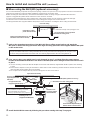
Connections (continued)
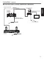
Connections with a controller ( AW-RP655 or AW-RP555)
LAN cable (straight cable) Pan-tilt head/
camera control signals HD Integrated Camera
AW-HE120
Multi Hybrid
Control Panel
AW-RP555 HDMI/SDI/Analog video signal
AC Adapter
AW-PS550 Accessory AC adaptor
Monitor
Multi-Function Controller
AW-RP655 AC Adapter
AW-PS550
DC cable with ø 5.5 plug
(supplied with the AW-PS550)

20
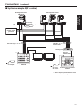
Connections (continued)
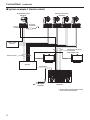
System example 1 (Serial control)
Accessory
AC adaptor
RS-422
connector
HD Integrated Camera
AW-HE120 HD Integrated Camera*
AW-HE120
SDI video signal
Switcher
Monitor 1 Monitor 2
Monitor Monitor
Pan-tilt head and camera
control signal
(LAN straight cable)
System TALLY
AC Adapter
AW-PS550
Multi-Function Controller
AW-RP655
Genlock signal
generator
*: The AC adaptor provided with the unit is
not shown in the above figure.
La pagina si sta caricando...
La pagina si sta caricando...
La pagina si sta caricando...
La pagina si sta caricando...
La pagina si sta caricando...
La pagina si sta caricando...
La pagina si sta caricando...
La pagina si sta caricando...
La pagina si sta caricando...
La pagina si sta caricando...
La pagina si sta caricando...
La pagina si sta caricando...
La pagina si sta caricando...
La pagina si sta caricando...
La pagina si sta caricando...
La pagina si sta caricando...
La pagina si sta caricando...
La pagina si sta caricando...
La pagina si sta caricando...
La pagina si sta caricando...
La pagina si sta caricando...
La pagina si sta caricando...
La pagina si sta caricando...
La pagina si sta caricando...
La pagina si sta caricando...
La pagina si sta caricando...
La pagina si sta caricando...
La pagina si sta caricando...
La pagina si sta caricando...
La pagina si sta caricando...
La pagina si sta caricando...
La pagina si sta caricando...
-
 1
1
-
 2
2
-
 3
3
-
 4
4
-
 5
5
-
 6
6
-
 7
7
-
 8
8
-
 9
9
-
 10
10
-
 11
11
-
 12
12
-
 13
13
-
 14
14
-
 15
15
-
 16
16
-
 17
17
-
 18
18
-
 19
19
-
 20
20
-
 21
21
-
 22
22
-
 23
23
-
 24
24
-
 25
25
-
 26
26
-
 27
27
-
 28
28
-
 29
29
-
 30
30
-
 31
31
-
 32
32
-
 33
33
-
 34
34
-
 35
35
-
 36
36
-
 37
37
-
 38
38
-
 39
39
-
 40
40
-
 41
41
-
 42
42
-
 43
43
-
 44
44
-
 45
45
-
 46
46
-
 47
47
-
 48
48
-
 49
49
-
 50
50
-
 51
51
-
 52
52


VADDIO 999-6120-000W Manuale del proprietario
- Categoria
- Apparecchiature musicali supplementari
- Tipo
- Manuale del proprietario
in altre lingue
- English: VADDIO 999-6120-000W Owner's manual
Altri documenti
-
Panasonic AK-HRP200G Operating Instructions Manual
-
i-PRO i-PRO WV-S71300-F3 Network Camera Manuale utente
-
-
JVC TK-C655 Manuale utente
-
Sharp XG-NV51XE Manuale utente
-
Hitachi RAI-50PPD Istruzioni per l'uso
-
JVC TK-C625 Manuale utente
-
SonicWALL SonicWave 432i Guida Rapida
-
JVC TK-C1431EG Manuale utente