Gemini Stereo Amplifier XPM-3000 Manuale utente
- Categoria
- Amplificatori audio
- Tipo
- Manuale utente
Questo manuale è adatto anche per

(1)
MULTI LANGUAGE INSTRUCTIONS:
English.......................................................................................................................Page 5
Deutsch.....................................................................................................................Page 9
Español....................................................................................................................Page 14
Francais.................................................................................................Page 19
Italiano...................................................................................................Page 24
OPERATIONS MANUAL
BEDIENUNGSHANDBUCH
MANUAL DEL OPERADOR
MANUEL D’INSTRUCTIONS
XPM-3000
POWER AMPLIFIER
STEREO VERSTÄRKER
AMPLIFICADOR DE PODER ESTEREO
AMPLIFICATEUR DE PUISSANCE STÉRÉOV

(2)
11
7
12
13
6
14 15
8
9
10
20
22 23
21
1 2
3 4 5
8
9
10
18
16
17
19
11
7
12 13
6
14 15
1 2
3 4 5
18
16
17
18
16
17
120V
230V
Gemini Sound Products Corp.
120 Clover Place, Edison, NJ 08818• USA
Tel (732) 738-9003 • Fax (732) 738-9006

(3)
120V

(4)
230V

(5)
Connections, Controls and Indicators
Rear Panel
Note: 120V and 230V units have different types of output
connectors on the rear panel.
Input Section:
There are two parallel input connectors (one female XLR and one
1/4” jack) per channel. Either can be used as an input or as a link to
chain amplifiers.
XLR Input Jacks (11, 14): electronically balanced inputs accept a
standard XLR male connector. Pin 1 = shield/ground, pin 2 = hot or
positive (+) and pin 3 = cold or negative (-).
1/4" Input Jacks (12, 13): accept a balanced as well as an unbalanced
line level signal. The unbalanced line uses a standard tip-sleeve
connection. The tip is positive and the sleeve is negative/ground. The
balanced line uses a tip-ring-sleeve connection. Tip = hot or positive
(+), ring = cold or negative (-), and sleeve = shield/ground.
Signal Ground Lift Switch (15) is used to lift the balanced input
connectors’ ground/shield from the amplifier’s ground. When the
signal ground is lifted, the sound source disconnects from the
amplifier’s ground preventing ground loops which can generate hum
and noise. See the Signal Ground Lift Switch Instructions for more
detail.
AC Power Section:
Fuse (7): replace fuse with those of proper type and rating.
AC Cord Outlet (6) is used to attach the power cord to the unit.
Signal Processing Section:
Disconnect the unit from the AC power source before making any
connections.
Crossover Switch (3): Use the crossover
switch to set the crossover frequency
between the subwoofer and the satellite
channels (Channels A and B) at 120 Hz or
180 Hz. Or you can set the crossover
switch to FULL RANGE if you do not wish
to use a subwoofer (the full range signal
will then go to the satellite channels).
Low Frequency Boost Switch (4): The LF Boost Switch can be used to
optimize the performance of the subwoofer. The LF boost effect uses
specialized filter circuitry, including a subsonic filter, to cut off
subsonic frequencies which keeps the subwoofer from wasting
available energy. The filter also provides an
optional +3 dB or +6 dB boost at 40 Hz which
is suitable for most subwoofers. The circuitry
optimizes the performance of the
subwoofer by focusing the signal’s energy
to match the subwoofer’s characteristics.
Set the switch to be FLAT, +3 dB or +6
dB based on your subwoofer and your
experience.
NOTE: The LF Boost settings only effect the subwoofer
channel and will not effect the satellite channels.
Line Outputs (1, 2, 5): the amplifier has quasi balanced post crossover
line outputs. The line outputs connectors are 1/4” TRS and can be
used to connect to additional amplifiers (optional).
Output Section:
Speaker Outputs:
Pay close attention to polarity (shown on the back of the unit) when
connecting your speakers. Connecting your speaker systems using the
wrong polarity will not damage your speakers, but it will impact the
quality of the sound (lack of bass and incorrect stereo image).
Speaker Outputs for 120V Unit (8, 9, 10): the speaker output
connectors are 5-way binding posts that will accept standard banana
plugs, spade lugs or bare wire. Make sure that all the connections are
clean when using bare wire connections. If any strands of wire from
Introduction
Congratulations on purchasing a Gemini XPM-3000 Power Amplifier.
This state of the art power amplifier includes the latest features and is
backed by a five year limited warranty. Prior to use, we suggest that you
carefully read all the instructions.
Features
• MOSFET output stage technology for the finest sound quality and
reliability
• 3 Channel Operation: 2 Satellite Channels (Channels A and B) and 1
Subwoofer Channel
• Full range operation mode for set up without subwoofer(s)
• 2-way Linkwitz-Riley crossover with switchable crossover frequency
for flexible set up of subwoofer and satellite channels
• Switchable low frequency boost on the subwoofer channel optimizes
subwoofer performance
• Stable operation of subwoofer channel down to a 2 Ohm load
• Post crossover line level outputs for chaining additional subwoofers
and satellite speakers
• High output power to drive professional loudspeakers without clipping
• Oversized toroidal transformer, filter and heatsinks for better low end,
transparency and stability
• Comprehensive protection circuitry (short, overheat, DC, subsonic
and RF filters, turn-on delay) with high current speaker protection
relays
• True clip LEDs for better control
• Signal ground lift switch eliminates hum from connection loops
• Flexible input configuration with active balanced inputs; additional
input connectors to chain amps
• Outputs: 5-way binding posts in 120V; Neutrik Speakon connectors in
230V
• 2 parallel 5-way binding posts on the subwoofer output (in 120V only)
allows for easy set up with dual subwoofers
• Efficient dual aluminum extrusion heatsink design for thermal stability
and reliability
• Front-to-Rear airflow with 2 speed dual fan control
• Turn-on In-rush current limiting circuitry
• Compact 2U well balanced enclosure
• Steel reinforced chassis construction for durability and longevity
Cautions
Read all operating instructions before using this equipment.
To reduce the risk of electrical shock, do not open the unit. There
are NO USER REPLACEABLE PARTS INSIDE. Please contact the
Gemini Service Department or your authorized dealer to speak to a
qualified service technician.
Be sure to allow adequate front and rear ventilation to avoid possible
heat damage to your equipment.
Be sure that AC power is OFF and all level controls are set to MINIMUM
before making connections. This will eliminate any chance of
unexpected, loud audio transients that could damage your speaker
systems.
Be sure that AC power is OFF when changing modes of operation and
when changing the position of the ground lift switch.
DO NOT EXPOSE THIS UNIT TO RAIN OR MOISTURE. Operators of
electronic equipment should in no way be in contact with water.
When connecting to AC power line be sure you haven’t lost the ground
connection by using an adapter or extension cord without a 3 prong plug.
DO NOT USE ANY SPRAY CLEANER OR LUBRICANT ON ANY
CONTROLS OR SWITCHES.

(6)
one connector touch the adjacent connector, the sound will be
distorted, and your amplifier will overheat and go into protection
mode.
NOTE (120V only): Two subwoofer output connectors are
provided to connect two subwoofers with separate cables.
These outputs are wired in parallel and are connected to a
mono subwoofer channel (subwoofer output is not
directional and does not require a stereo signal). The
combined load for the subwoofer channel must not be less
than 2 Ohms (a single 2 Ohm speaker OR two 4 Ohm
speakers OR four 8 Ohm speakers).
Speaker Outputs for 230V Unit (8, 9, 10): Neutrik Speakon connectors
are provided to connect speakers to the amplifier quickly and easily.
They are high current rated and provide very stable and durable
contacts. Every Speakon connector has pin 1- as negative and pin
1+ as positive.
WARNING: The XPM-3000 amplifier is designed to handle
low impedance loads and will operate normally with most
2 Ohm subwoofers or subwoofer combinations. The
amplifier will operate normally with most 4 Ohm speakers
on the satellite channels. However, for optimal
performance and reliability we recommend using
subwoofers and speakers with higher impedance (4 Ohms
for the subwoofer and 8 Ohms for the satellite channels).
NOTE: There are no bridge connections in this amplifier.
Please refer to the terminals’ color coding for proper
connection polarity.
Front Panel
Power (23): the power switch turns the unit on and off.
Power LED (22): the power LED lights when the power is on. If the
power LED does not light, refer to the trouble shooting guide.
Signal LED (16): the signal LEDs for each channel show when a signal
is present.
Clip LED (17): the amplifier has true clip LEDs to help you properly
control the amplifier’s output and achieve undistorted sound. The clip
LEDs for each channel light when your signal level is so strong that
the distortion reaches 1% THD. The clip LED should not remain
constantly on or flash repeatedly during operation. For clean sound
reproduction, the clip should only light occasionally for an instant. If
the LED remains on or flashes repeatedly, you will hear distorted
sound that can be damaging to your speaker system. If this occurs,
reduce the signal level by lowering the input level control for the
channel that is clipping or reduce the level at the source. If the clip
LED lights when no signal is present, it may indicate a RF signal on
the output which may cause damage to speakers (the RF signal will
not be audible).
Protect LED (18): when you first turn on the amplifier, the protect LEDs
light briefly during a turn-on delay which indicates that the outputs are
disconnected internally. There will be an audible click when the
outputs reconnect and the protect LEDs will turn off. Otherwise, the
protect LED indicates that there is a problem either in the amplifier’s
external connections, load or temperature conditions or its internal
functions. If one of these situations occur, the amplifier senses the
problem and automatically switches into protection mode. The LED
will light to warn you of the trouble and the amplifier will stop working.
If this occurs, switch off the amplifier and refer to the Trouble
Shooting Guide. If the protect LED remains lit when resuming
amplifier operation, do not use the amplifier and contact an
authorized service technician.
Level Controls (19, 20, 21): establish the input levels required for each
channel.
Operating Instructions
THE AMPLIFIER’S POWER MUST BE TURNED OFF
WHEN CHANGING SETTINGS.
Using the Amplifier With Subwoofer(s) and Satellite
Speakers
The XPM-3000 has two channels for stereo operation and a common
subwoofer channel. The amplifier has a built in crossover to separate the
input signal between the stereo satellite channels and the mono
subwoofer channel (the low frequency signal feeding the subwoofer is
not directional and does not require stereo operation). The amplifier also
provides an optional low frequency boost for the subwoofer channel to
optimize the performance of your subwoofer.
1. With the power off, connect your input cables to the channel A and B
inputs using either the XLR INPUT JACKS (11, 14) or 1/4" INPUT
JACKS (12, 13) for each channel. The other channel A and channel
B inputs can be used to link to an additional amplifier.
2. Connect the subwoofer(s) to the subwoofer SPEAKER OUTPUT(S)
(10). Connect the full range loudspeakers to the channel A and
channel B SPEAKER OUTPUTS (8, 9). THE TOTAL SPEAKER
LOAD MUST BE AT LEAST 4 OHMS PER CHANNEL FOR THE
SATELLITE CHANNELS AND 2 OHMS FOR THE SUBWOOFER. If
you try to operate at a lower impedance, the amplifier will overheat
and then go into protection mode and stop operation until you correct
the load conditions.
3. If you choose to use additional amplifiers, connect the additional
amplifiers to the XPM-3000 using the LINE OUTPUT (1, 2, 5)
connectors.
NOTE: The line outputs tap the signal after the crossover
and the low frequency boost but before the level controls.
4. Use the CROSSOVER SWITCH (3) to set the crossover frequency
between the subwoofer and the satellite channels (Channels A and B)
at 120 Hz or 180 Hz.
5. Use the LOW FREQUENCY BOOST SWITCH (4) to optimize the
performance of the subwoofer. The LF boost effect uses specialized
filter circuitry, including a subsonic filter, to cut off subsonic
frequencies which keeps the subwoofer from wasting available
energy. The filter also provides an optional +3 dB or +6 dB boost at
40 Hz which is suitable for most subwoofers. Set the switch to be
FLAT, +3 dB or +6 dB based on your subwoofer and your experience.
NOTE: The LF Boost settings only effect the subwoofer
channel and will not effect the satellite channels.
6. With the LEVEL CONTROLS (19, 20, 21) of the channels set to zero
(fully counterclockwise), turn the POWER (23) on. Apply a signal to
the input of the amplifier. The level of the input signal should be as
high as you will ever need it to be. This way, it will be as high above
the amplifier’s noise floor as possible, ensuring an excellent
performance and signal to noise ratio. Adjust the LEVEL CONTROLS
for each channel to achieve the desired maximum listening level.
Note, when the clip LEDs light, there is distortion present in the
amplifier’s output section. If a clip LED remains on or flashes
repeatedly, reduce the signal level by lowering the input level control
for the channel that is clipping or reduce the level at the source.
Using the Amplifier Without Subwoofer(s)
The XPM-3000 gives you the option of operating the amplifier as you
would a conventional amplifier, without using subwoofer(s). This flexibility
is especially useful if you don’t want to transport your subwoofers at
times.
1. With the power off, connect your input cables to the channel A and B
inputs using either the XLR INPUT JACKS (11, 14) or 1/4" INPUT
JACKS (12, 13) for each channel. The other channel A and channel
B inputs can be used to link to an additional amplifier.

(7)
2. Connect the loudspeakers to the channel A and channel B SPEAKER
OUTPUTS (8, 9). THE TOTAL SPEAKER LOAD MUST BE AT
LEAST 4 OHMS PER CHANNEL FOR CHANNELS A AND B. If you
try to operate at a lower impedance, the amplifier will overheat and
then go into protection mode and stop operation until you correct the
load conditions.
3. If you choose to use additional amplifiers, connect the additional
amplifiers to the XPM-3000 using the LINE OUTPUT (1, 2)
connectors.
4. Set the CROSSOVER SWITCH (3) to FULL RANGE so that the full
range signal will go to the satellite channels (Channels A and B).
5. With the LEVEL CONTROLS (20, 21) of the channels set to zero
(fully counterclockwise), turn the POWER (23) on. Apply a signal to
the input of the amplifier. The level of the input signal should be as
high as you will ever need it to be. This way, it will be as high above
the amplifier’s noise floor as possible, ensuring an excellent
performance and signal to noise ratio. Adjust the LEVEL CONTROLS
for each channel to achieve the desired maximum listening level.
Note, when the clip LEDs light, there is distortion present in the
amplifier’s output section. If a clip LED remains on or flashes
repeatedly, reduce the signal level by lowering the input level control
for the channel that is clipping or reduce the level at the source.
Using the Signal Ground Lift Switch
Depending on your system configuration, sometimes applying the
ground will create a quieter signal path. Sometimes lifting the ground can
eliminate ground loops and hum to create a quieter signal path.
1. With the power amp on, listen to the system in idle mode (no signal
present) with the ground applied (the SIGNAL GROUND LIFT
SWITCH (15) in the left position).
2. Then turn the power off before moving the SIGNAL GROUND
LIFT SWITCH (15). Lift the ground by moving the SIGNAL GROUND
LIFT SWITCH to the right, turn the power back on and listen to
determine which position will provide a signal devoid of background
noise and hum. Keep the SIGNAL GROUND LIFT SWITCH in the
ground position if the noise level remains the same in either position.
CAUTION: DO NOT TERMINATE THE AC GROUND ON THE POWER
AMPLIFIER IN ANY WAY. TERMINATION OF THE AC GROUND CAN
BE HAZARDOUS.
Specifications
Output Power EIA: 1kHz @ 1% THD (100 Hz @ 1% THD for the
subwoofer channel)
Note: the power for channels A and B is given as per channel, both
channels driven
Frequency Response - 3 Channel Operation:
Channels A and B.......................................Crossover Frequency - 60 kHz
Subwoofer Channel.....................................20 Hz - Crossover Frequency
Frequency Response - Full Range Operation:
Channels A and B.................................................................20 Hz - 60 kHz
Crossover:
Type.................................................................2nd order Linkwitz-Riley
Crossover Frequency....................................................120 Hz/180 Hz
Low Frequency Boost:
Boost Frequency..............................................................................40 Hz
Boost Level..............................................................................+3 dB/+6 dB
Signal to Noise Ratio..........................100 dB below rated power, 8 Ohms
Damping Factor:
Channels A and B................................................................>300 @ 8 Ohms
Subwoofer Channel.............................................................>600 @ 8 Ohms
Slew Rate.................................................................................25 V/µS
Voltage Gain.........................................................................................33 dB
Input Sensitivity:
Channels A and B (for rated power at 8 Ohms)....................>300 @ 8 Ohms
Subwoofer Channel (for rated power at 4 Ohms)...................>600 @ 8 Ohms
Input Impedance Unbalanced....................................................10 kOhms
Input Impedance Balanced.......................................................20 kOhms
Power consumption.....................................................................1200 VA
Note: power consumption is given at rated power at 8 Ohms per channel
(Channels A and B), 4 Ohms on the subwoofer channel, all three
channels driven.
AC Power Requirement:
(power connection is factory configured)............................120V/ 60 Hz
230V/ 50 Hz
Indicators.......................................................................1 Power Indicator
1 Signal LED per channel
1 Clip LED per channel
1 Protect LED per channel
Cooling....................................2 Speed Dual Fan; Front-to-Rear Forced Air
Protection........................Short Circuit, DC, Thermal Cut-off, Sub/ultrasonic
Frequency Filters, In-rush Current Limiter, Turn-on Delay
Connectors:
Balanced/Unbalanced Inputs.......................................................1/4" Jack
Balanced Inputs..............................................................XLR Female Jack
Line Outputs...............................................................................1/4" Jack
Speaker Outputs (120V unit).......................................5-way binding posts
2 Parallel 5-way binding posts for subwoofers
Speaker Outputs (230V unit)...........Speakons (ch.A, ch.B and subwoofer)
Dimensions...................................19" x 13.75" x 3.5" (483 x 350 x 89 mm)
Weight....................................................................................31 lbs (14 kg)
* Specifications and design are subject to change without notice for
purpose of improvement.
Ouput Power Chart:
Impedance
Subwoofers
A and B
Speakers
8 Ohms
8 Ohms
Not
Used
4 Ohms 2 Ohms
4 Ohms
Not Used
300
260
220
200
425
380
190
350
270
600
540
165
530
250
220

(8)
UNIT DOES NOT PRODUCE SOUND. POWER
LED DOES NOT LIGHT.
• POWER SWITCH NOT IN ON POSITION.
• POWER CABLE NOT CONNECTED TO AMPLIFIER
OR TO OUTLET.
• AC OUTLET NOT ACTIVE.
• MAIN AMPLIFIER FUSE DEFECTIVE.
• MOVE POWER SWITCH TO ON POSITION.
• CONNECT POWER CABLE TO AC SUPPLY.
• CHECK CONDITION OF OUTLET.
• REPLACE AMPLIFIER MAIN POWER FUSE ON REAR
PANEL WITH CORRECT TYPE AND RATING.
POWER LED LIGHTS, BUT NO SOUND IS
PRODUCED BY AMPLIFIER.
• NO INPUT SOURCE SIGNAL.
• INPUT SOURCE NOT CONNECTED.
• INPUT CONNECTING CABLE DEFECTIVE.
• SPEAKER(S) NOT CONNECTED.
• SPEAKER CABLE DEFECTIVE.
• SPEAKER SYSTEM(S) INOPERATIVE.
• AMPLIFIER’S LEVEL CONTROLS ARE SET TO
ZERO.
• CHECK FOR PROPER FUNCTION OF INPUT
SOURCE DEVICE.
• CHECK INPUT CABLES AND CONNECTIONS.
REPLACE QUESTIONABLE CABLES WITH KNOWN
GOOD CABLES.
• CHECK SPEAKER CABLES AND CONNECTIONS.
REPLACE QUESTIONABLE CABLES WITH KNOWN
GOOD CABLES.
• CHECK OPERATING CONDITION AND STATUS OF
SPEAKER SYSTEM(S). BE SURE THE LEVEL
CONTROLS ARE PROPERLY SET.
SOUND IS PRESENT BUT VOLUME IS TOO
LOW EVEN THOUGH SOURCE DEVICE IS
SET TO A HIGH LEVEL.
• AMPLIFIER INPUT LEVEL CONTROLS ARE SET
TOO LOW.
• WRONG PIN CONNECTIONS IN CABLES.
• ADJUST LEVEL CONTROLS AS PER INSTRUCTIONS.
• USE CORRECT CABLES (AS SHOWN ON BACK OF
UNIT).
LOUD 50/60 HZ OR 100/120 HZ HUM IS
HEARD AT ALL TIMES THROUGH THE
SPEAKER SYSTEMS.
• IMPROPER OR DEFECTIVE GROUND
CONNECTION AT INPUTS. IMPROPER OR
DEFECTIVE GROUND AT INPUT SOURCE
DEVICE(S).
• IMPROPER OR DEFECTIVE GROUND
CONNECTION ON AC OUTLET.
• GROUND LOOP THROUGH AC LINE
CONNECTION/RACK MOUNTING.
• CHECK FOR PROPER AC LINE GROUND ON POWER
AMP AND ALL INPUT DEVICES.
• CHECK INPUT CABLES FOR ALL SOURCE DEVICES
AND SIGNAL PROCESSING AS WELL AS INPUT
CABLES TO POWER AMPLIFIER. CHECK POSITION
OF GROUND LIFT SWITCH AS PER INSTRUCTIONS
FOR LIFTING THE GROUND.
• NEVER LIFT THE AC LINE GROUND ON THE POWER
AMPLIFIER. IF YOU ARE NOT TOTALLY FAMILIAR WITH
GROUND LIFTING OR UNIFICATION PROCEDURES,
DO NOT ATTEMPT THEM WITHOUT FIRST
CONSULTING YOUR DEALER OR A QUALIFIED
SOUND TECHNICIAN FOR MORE INFORMATION ON
GROUNDING. IMPROPERLY DONE, SUCH
PROCEDURES CAN POSE A SAFETY AND/OR FIRE
HAZARD.
SOUND IS DISTORTED.
• DISTORTION OCCURRING IN SOURCE DEVICE.
• INPUT LEVEL IS SET TOO HIGH.
• CHECK CLIP INDICATORS ON INPUT SOURCE
DEVICES AND RESET LEVELS IF NECESSARY TO
ELIMINATE DISTORTION.
• ADJUST LEVEL CONTROLS AS PER INSTRUCTIONS.
PROTECT LED REMAINS LIT OR GOES ON
AND OFF INTERMITTENTLY AFTER USING
AMPLIFIER FOR A SHORT TIME.
• UNIT IS OPERATING AT EXCESSIVELY HIGH
TEMPERATURE.
• EXTREMELY LOW SPEAKER IMPEDANCE.
• SHORT IN SPEAKER CONNECTORS,
SPEAKER CABLE OR SPEAKER SYSTEM.
• CHECK THAT AMPLIFIER IS ADEQUATELY
VENTILATED ON THE FRONT AND REAR PANELS
WHERE THE AIR VENTS AND FANS ARE LOCATED.
IF OVERHEATED, LET THE AMPLIFIER COOL DOWN
BEFORE APPLYING AN INPUT SIGNAL.
• VERIFY SPEAKER SYSTEM IMPEDANCES. BE SURE
THE TOTAL SPEAKER SYSTEM IMPEDANCE IS AT
LEAST 4 OHM PER CHANNEL FOR CHANNELS A AND
B, AND AT LEAST 2 OHM FOR THE SUBWOOFER
CHANNEL. IF YOU ARE NOT SURE OF YOUR TOTAL
SPEAKER IMPEDANCE LOAD, CONTACT YOUR
DEALER FOR MORE INFORMATION.
• CHECK CONDITION OF SPEAKER CABLES.
• IF USING BARE WIRE CONNECTIONS ON THE
OUTPUTS OF THE AMPLIFIER, BE SURE THAT NO
STRANDS FROM ONE CONNECTOR ARE TOUCHING
ANY OTHER CONNECTOR.
FUSE BLOWS INTERMITTENTLY.
• SPEAKER LOAD IMPEDANCE IS TOO LOW.
• TYPE OR RATING OF THE FUSE IS NOT
CORRECT.
• CHECK FOR SHORTS ON THE OUTPUTS.
• CHECK YOUR SPEAKER IMPEDANCE (INFO FROM
DEALER).
• CHECK THAT THE FUSE TYPE AND RATING IS
CORRECT.
PROTECT LED(S) STAY ON WITH NO
SPEAKERS CONNECTED AND WITH THE
AMPLIFIER COOLED DOWN.
• FAILED AMPLIFIER.
• CONTACT THE GEMINI SERVICE DEPARTMENT OR
YOUR AUTHORIZED DEALER TO SPEAK TO A
QUALIFIED SERVICE TECHNICIAN. IN THE U.S.A. CALL
1-732-969-9000
SYMPTOM CAUSE SOLUTION
VERY LITTLE OR NO OUTPUT FROM
SUBWOOFER OR
NO BASS FROM FULL RANGE SPEAKERS
WHEN OPERATING WITHOUT
SUBWOOFERS.
• FREQUENCY SWITCH IS IN THE FULL RANGE
MODE POSITION.
• MOVE THE FREQUENCY SWITCH TO THE 120 HZ
OR THE 180 HZ POSITION.

(9)
Einleitung
Wir gratulieren Ihnen zum Kauf eines Gemini XPM-3000
Endverstärkers. Dieser moderne Endverstärker enthält die neuesten
Funktionen und besitzt eine fünfjährige begrenzte Garantie. Vor
Anwendung dieses Gerätes bitte alle Anweisungen sorgfältig durchlesen.
Funktionen
• MOSFET-Ausgangsstufen-Technologie für feinste Tonqualität und
Zuverlässigkeit
• Dreikanalbetrieb: 2 Satellitenkanäle (Kanäle A und B) und 1
Tieftonlautsprecherkanal
• Kompletter Frequenzbereich bei Betriebsmodus für Aufbau ohne
Tieftonlautsprecher
• 2-weg Linkwitz-Riley Frequenzweiche mit umschaltbarer
Überschneidungsfrequenz für flexible Anpassung des
Tieftonlautsprechers und der Satelitenkanäle
• Schaltbare Tieftonpegelanhebung am Tieftonlautsprecherkanal
optimiert die Leistung des Tieftonlautsprechers
• Stabiler Betrieb des Tieftonlautsprecherkanals bis zu einer Belastung
von 2 Ohm
• Zusätzliche Ausgänge zum Anschluß weiterer Endstufen für Tiefton-
und Satelitenlautsprecher
• Hohe Ausgangsleistung, um professionelle Lautsprecher ohne
Übersteuerung zu treiben
• Überdimensionierte Ringtransformatoren, Filter und Kühlkörper für
bessere Basis, Transparenz und Beständigkeit
• Umfassender Schutzschaltungsaufbau (Kurzschluß-, Überhitzungs-,
Gleichstrom-, Unterschall- und Funkfilter, Einschaltverzögerung) mit
Hochstrom-Lautsprecher-Schutzrelais
• Echte Übersteuerungs-LEDs für bessere Kontrolle
• Der Signal-Massetrennschalter schaltet das durch Masseschleifen
erzeugte Brummen aus
• Flexible Eingangskonfiguration mit symmetrischen Eingängen;
zusätzliche Eingangsanschlüsse, um Verstärker zu verketten
• Ausgänge: Fünfwegige Polklemmen für 120-V-Versionen; Neutrik
Speakon-Anschlüsse für 230-V-Versionen
• 2 parallele fünfwegige Polklemmen am Tieftonlautsprecherausgang
(nur für 120-V-Einheiten) ermöglichen leichten Aufbau mit Doppel-
Tieftonlautsprechern
• Effiziente Kühlung in doppelten Alu-Profilen bietet
Wärmebeständigkeit und Betriebssicherheit
• Durchgehende Lüfterkühlung mit zwei Ventilatoren und
Zweigeschwindigkeits-Regelung
• Einschaltstrom-Begrenzerschaltkreis
• Kompaktes Gehäuse mit 2 Höheneinheiten
• Stahlverstärkte Chassisausführung für Haltbarkeit und Langlebigkeit
Vorsichtsmaßnahmen
Vor Anwendung des Geräts lesen Sie bitte alle Anweisungen sorgfältig
durch.
Um das Risiko elektrischen Schocks zu vermeiden, dürfen Sie das Gerät
nicht öffnen. DAS GERÄT ENTHÄLT KEINE VOM ANWENDER
ERSETZBARE TEILE. Wenden Sie sich bitte an das Gemini Service
Department oder an Ihren Vertragshändler, um mit einem befähigten
Wartungstechniker zu sprechen.
Sicherstellen, daß die Vorder- und Rückseite gut ventiliert sind, um
mögliche Beschädigung der Ausrüstung durch Überhitzen zu vermeiden.
Sicherstellen, daß der Leistungsstrom ausgeschaltet ist und alle
Tonstärkenregler auf MINIMUM geschaltet sind. Dies wird die Möglichkeit
unerwarteter, lauter Einschwingungen eliminieren, die das
Lautsprechesystem beschädigen könnten.
Sicherstellen, daß der Leistungsstrom ausgeschaltet ist, wenn die
Betriebsarten und die Position des Massetrennschalters geändert
werden.
DAS GERÄT NIEMALS REGEN ODER FEUCHTIGKEIT AUSSETZEN.
Bediener von elektronischen Geräten dürfen unter keinen Umständen
Kontakt mit Wasser haben.
Beim Anschluß an die Netzleitung sicherstellen, daß der Masseanschluß
nicht verlorengeht, wenn eine Adapter- oder Verlängerungsschnur ohne
Schukostecker benutzt wird.
KEIN REININGSSPRAY ODER SCHMIERMITTEL AN DEN REGLERN
ODER SCHALTERN VERWENDEN.
Anschlüsse, Regler und Anzeigen
Rückseite
Hinweis: 120-V- und 230-V-Einheiten haben
unterschiedliche Ausgangsanschlüsse an der Rückseite.
Eingangsbereich:
Jeder Kanal hat zwei parallele Eingangsanschlüsse (eine XLR-
Buchse und eine 1/4-Zoll-Buchse). Sie können beide als Eingang oder
Verbindung zur Verkettung von Verstärkern benutzt werden.
XLR-Eingangsbuchsen - XLR Input Jacks (11, 14): Elektronisch
symmetrische Eingänge nehmen einen XLR-Standardstecker auf.
Stift 1 = Abschirmung/Masse, Stift 2 = heiß bzw. plus (+), 3 = kalt
bzw. minus (-).
Klinken-Eingangsbuchsen - 1/4" Input Jacks (12, 13): Diese Buchsen
nehmen symmetrische sowie unsymmetrische
Leitungseingangssignale auf. Die unsymmetrische Leitung benutzt
eine Standard-Spitzen-Muffen-Verbindung. Die Spitze ist negativ und
die Muffe positiv geerdet. Die symmetrische Leitung benutzt eine
Spitzen-Ring-Muffen-Verbindung. Spitze = heiß bzw. plus (+), Ring =
kalt bzw. minus (-) und Muffe = Abschirmung/Masse.
Der Signalmasse-Trennschalter - Signal Ground Lift Switch (15) wird
benutzt, um die Masse/Abschirmung der symmetrischen
Eingangssteckverbindungen von der Masse des Verstärkers zu
trennen. Wenn die Signalmasse getrennt ist, wird die Klangquelle von
der Masse der Verstärker getrennt, wodurch Masseschleifen
verhindert werden, die Brummen und Störungen verursachen.
Einzelheiten finden Sie in den Anweisungen für den Signal-
Massetrennschalter.
Netzstrom:
Sicherung - Fuse (7): Beim Auswechseln eine Sicherung ist darauf zu
achten, daß die Sicherungsart und -bemessung korrekt sind.
Netzleitungs-Steckbuchse - AC Cord Outlet (6): Diese Buchse wird
benutzt, um die Netzleitung an der Einheit anzuschließen.
Signalverarbeitungsbereich:
Bevor jegliche Verbindungen hergestellt werden, muß die Einheit von
der Stromquelle getrennt werden.
Frequenzweichenschalter - Crossover Switch (3): Benutzen Sie den
Frequenzweichenschalter, um die
Übergangsfrequenz zwischen dem
Tieftonlautsprecher und den
Satellitenkanälen (Kanäle A und B) bei
120 Hz oder 180 Hz einzustellen. Sie
können den Schalter auch auf FULL RANGE
(Volle Bandbreite) einstellen, falls kein
Tieftonlautsprecher benutzt werden soll (das
Signal für volle Bandbreite wird dann an die
Satellitenkanäle übertragen).
Basspegelanhebungsschalter - Low Frequency Boost Switch (4):
Dieser Schalter kann benutzt werden, um die Leistung des
Tieftonlautsprechers zu optimieren. Für die Pegelanhebung werden
besondere Filterschaltkreise benutzt, einschließlich Subsonic-Filter,
um Subsonic-Frequenzen auszuschalten,
wodurch der Tieftonlautsprecher daran
gehindert wird, Energie zu vergeuden. Die
Filter bieten ebenfalls eine optimale
Verstärkung von +3 dB oder +6 dB bei 40
Hz, welches für die meisten
Tieftonlautsprecher angemessen ist. Die
Schaltung optimiert die Leistung des

(10)
Tieftonlautsprechers, indem sie die Signalenergie darauf fokussiert,
die Kenndaten des Tieftonlautsprechers anzupassen. Beruhend auf
Ihrem Tieftonlautsprecher und entsprechend Ihrer Erfahrung, stellen
Sie den Schalter auf FLAT (flach) ein, bzw. +3 dB oder +6 dB.
HINWEIS: Die Einstellungen der Bassanhebung haben nur
Einfluss auf den Tieftonlautsprecherkanal, jedoch nicht
auf die Satellitenkanäle.
Audio-Ausgänge - Line Outputs (1, 2, 5): Der Verstärker hat quasi
symmetrische Audio-Ausgänge nach der Frequenzweiche. Die
Anschlüsse sind 6.3mm-Klinkenbuchsen und können an zusätzliche
Verstärker angeschlossen werden (wahlweise).
Ausgänge:
Lautsprecher-Ausgänge:
Beim Anschluß der Lautsprecher ist besonders auf die Polarität zu
achten (wie an der Rückseite der Einheit dargestellt. Wird das
Lautsprechersystem mit falscher Polarität angeschlossen, werden
dadurch die Lautsprecher zwar nicht beschädigt, doch wird dies einen
Einfluß auf die Tonqualität ausüben (kein Baßton und falsches Stereo-
Image).
Lautsprecher-Ausgänge für 120-V-Versionen - Speaker Outputs for
120V Unit (8, 9, 10): Die Lautsprecher-Ausgangsbuchsen sind
fünfpolige Polklemmen, die Standard-Bananenstecker, Gabelstecker
oder blanke Drähte aufnehmen. Sicherstellen, daß bei blanken
Anschlüssen alle Anschlüsse sauber sind. Falls irgendwelche Litzen
oder Drähte eines Anschlusses den benachbarten Anschluß
berühren, ergibt sich eine Klangverzerrung und der Verstärker wird
sich überhitzen und in den Schutzmodus umschalten.
HINWEIS (nur für 120-V-Einheiten): Zwei
Tieftonlautsprecheranschlüsse sind angebracht, um die
beiden Tieftonlautsprecher mit separaten Kabeln zu
verbinden. Diese Ausgänge sind parallel verdrahtet und an
einem Mono-Tieftonlautsprecherkanal angeschlossen (die
Ausgabe des Tieftonlautsprechers ist nicht
richtungsabhängig und erfordert kein Stereosignal). Die
kombinierte Belastung der Tieftonlautsprecherkanäle darf
nicht weniger als 2 Ohm betragen (ein einziger 2-Ohm-
Lautsprecher ODER zwei 4-Ohm-Lautsprecher ODER vier 8-
Ohm-Lautsprecher).
Lautsprecher-Ausgänge für 230-V-Versionen - Speaker Outputs for
230V Unit (8, 9, 10): Neutrik Speakon-Anschlüsse sind vorgesehen,
um die Lautsprecher schnell und leicht am Verstärker anzuschließen.
Sie sind hochbelastbar und bieten feste und haltbare Kontakte. Jeder
Speakon-Anschluß hat einen Plus-Stift 1 (+) und einen Minus-Stift 1 (-).
WARNUNG: Der XPM-3000 Verstärker wurde so
konstruiert, um niederohmige Belastungen zu bewältigen,
und wird mit den meisten 2-Ohm-Tieftonlautsprechern
oder Tieftonlautsprecherkombinationen normal arbeiten.
Der Lautsprecher wird mit den meisten am Satellitenkanal
angeschlossenen 4-Ohm-Lautsprechern normal arbeiten.
Um optimale Leistung und Zuverlässigkeit zu erzielen,
empfehlen wir jedoch, Tieftonlautsprecher und
Lautsprecher mit höherer Impedanz zu verwenden (4 Ohm
für den Tieftonlautsprecher und 8 Ohm für die
Satellitenkanäle).
HINWEIS: Bei diesem Verstärkern gibt es keine
Brückenanschlüsse. Um den richtigen Anschluss
sicherzustellen, siehe Farbkodierung an der
Anschlussklemme.
Vorderseite
Netzschalter - Power (23): Dieser Schalter schaltet die Einheit ein und
aus.
Netz-LED - Power LED (22): Die Netz-LED leuchtet, wenn der Strom
eingeschaltet ist. Wenn die Netz-LED nicht leuchtet, siehe
Fehlerbeseitigungs-Handbuch.
Signal LED (16): Die Signal-LEDs für jeden Kanal zeigen an, wenn ein
Audio-Signal vorhanden ist.
Übersteuerungs-LED - Clip LED (17): Der Verstärker besitzt echte
Übersteuerungs-LEDs, um Ihnen zu helfen, den Ausgang des
Verstärkers richtig zu regeln und um einen entzerrungsfreien Klang
zu erzielen. Die Übersteuerungs-LEDs eines jeden Kanals leuchten,
wenn der Signalpegel so hoch ist, so daß die Verzerrung 1% des
Gesamtklirrfaktors erreicht. Während des Betriebs sollte die
Übersteuerungs-LED nicht ständig aufleuchten oder wiederholt
blinken. Bei einer klaren Klangwiedergabe sollte die LED nur hin und
wieder kurz aufblinken. Bleibt die LED eingeschaltet oder blinkt
wiederholt, hören Sie einen verzerrten Klang, wodurch das
Lautsprechersystem beschädigt werden kann. In einem solchen Fall
ist der Signalpegel am Eingangspegelregler des übersteuernden
Kanals bzw. der Eingangspegel an der Tonquelle zu reduzieren.
Leuchtet die Übersteuerungs-LED, wenn kein Signal zugegen ist,
kann dies ein Funksignal am Ausgang anzeigen, wodurch das
Lautsprechersystem beschädigt werden kann (das Funksignal ist
nicht hörbar).
SCHUTZ-LED - Protect LED (18): Wenn der Verstärker zuerst
eingeschaltet wird, leuchten die Schutz-LEDs kurz während einer
Einschaltverzögerung auf, welches anzeigt, daß die Ausgänge intern
getrennt sind. Ein Klickton deutet an, daß die Ausgänge wieder
angeschlossen sind, und die Schutz-LEDs erlöschen. Andernfalls
zeigen die Schutz-LEDs an, daß in den Außenanschlüssen des
Verstärkers, in seinen Belastungs- oder Temperaturzuständen oder
bei seinen inneren Funktionen ein Problem besteht. Falls eine dieser
Zustände eintritt, erkennt der Verstärker das Problem und schaltet
automatisch zum Schutzmodus über. Die LED wird aufleuchten, um
Sie vor der Störung zu warnen, und der Verstärker unterbricht seinen
Betrieb. Falls dies eintritt, müssen Sie den Verstärker ausschalten
und das Fehlerbeseitungungs-Handbuch zu Rate ziehen. Bleibt die
Schutz-LED immer noch im erleuchteten Zustand nachdem der
Verstärker seinen Betrieb wieder aufgenommen hat, darf dieser nicht
weiter verwendet werden, und ein befugter Wartungstechniker
muß zu Rate gezogen werden.
Pegelregler - Level Controls (19, 20, 21): Diese Regler regeln die für
jeden Kanal erforderlichen Signalpegel.
Betriebanweisungen
DIE VERSTÄRKER MüSSEN BEIM WECHSEL
DER BETRIEBSART AUSGESCHALTET SEIN.
Verstärker mit Tieftonlautsprecher und
Satellitenlautsprecher benutzen
Der XPM-3000 hat zwei Kanäle für Stereobetrieb und einen Mono-
Tieftonlautsprecherkanal. Der Verstärker hat eine eingebaute
Frequenzweiche, um das Eingangssignal zwischen den Stereo-
Satellitenkanälen und dem Mono-Tieftonlautsprecherkanal (das dem
Tieftonlautsprecher zugeführte Niederfrequenzsignal erfordert keinen
Stereobetrieb) von einander zu trennen. Der Verstärker erzeugt
ebenfalls wahlweise eine Pegelanhebung für den
Tieftonlautsprecherkanal, um die Leistung des Tieftonlautsprechers zu
optimieren.
1. Wenn der Netzstrom ausgeschaltet ist, verbinden Sie die
Eingangskabel an den Eingängen von Kanal A und B, wobei
entweder die XLR-Eingangsbuchsen - XLR INPUT JACKS (11, 14)
oder die Klinken-Eingangsbuchsen - 1/4" INPUT JACKS (12, 13)
eines jeden Kanals benutzt werden. Die anderen Eingänge von Kanal
A und B können zwecks Verbindung mit zusätzlichen Verstärkern
benutzt werden.
2. Den (die) Tieftonlautsprecher am Lautsprecherausgang -
SPEAKER OUTPUT(S) (10) des Tieftonkanales anschließen. Die
Satelliten-Lautsprecher an den Lautsprecherausgängen -
SPEAKER OUTPUTS (8, 9) der Kanäle A und B anschließen. DIE
GESAMTBELASTUNG DER LAUTSPRECHER MUSS
MINDESTENS 4 OHM PRO KANAL FÜR DIE SATELLITENKANÄLE
UND 2 OHM FÜR DEN TIEFTONLAUTSPRECHER BETRAGEN.
Wenn Sie versuchen, die Lautsprecher bei einer niedrigeren
Impedanz zu betreiben, wird die Endstufe überhitzen, in den
Schutzmodus umschalten und dann den Betrieb anhalten, bis Sie

(11)
den Belastungszustand korrigiert haben.
3. Wenn Sie zusätzliche Verstärker benutzen wollen, schließen Sie
diese mittels den Anschlüssen der Audio-Ausgänge - LINE
OUTPUT (1, 2, 5) am XPM-3000 an.
HINWEIS: Die Signale werden nach der Frequenzweiche
und der Bass-Pegelanhebung, jedoch vor den Pegelreglern
von den Audio-Ausgängen abgenommen.
4. Benutzen Sie den Frequenzweichenschalter - CROSSOVER
SWITCH (3), um die Übergangsfrequenz zwischen dem
Tieftonlautsprecher und den Satellitenkanälen (Kanäle A und B) bei
120 Hz oder 180 Hz einzustellen.
5. Benutzen Sie den Bass-Pegelschalter - LOW FREQUENCY
BOOST SWITCH (4), um die Leistung des Tieftonlautsprechers zu
optimieren. Für den Tiefton-Verstärkungseffekt werden besondere
Filterschaltkreise benutzt, einschließlich Subsonic-Filter, um
Subsonic-Frequenzen auszuschalten, wodurch der
Tieftonlautsprecher daran gehindert wird, Energie zu vergeuden.
Beruhend auf Ihrem Tieftonlautsprecher und entsprechend Ihrer
Erfahrung, stellen Sie den Schalter auf FLAT (flach) ein, bzw. +3 dB
oder +6 dB.
HINWEIS: Die Einstellungen der Bassanhebung haben nur
Einfluss auf den Tieftonlautsprecherkanal, jedoch nicht
auf die Satellitenkanäle.
6. Wenn die Pegelregler - LEVEL CONTROLS (19, 20, 21) an beiden
Kanälen (vollkommen nach links) auf Null gestellt sind, den
Netzschalter - POWER (23) einschalten. An den Eingang des
Verstärkers ein Signal anlegen. Der Pegel des Eingangssignals sollte
so hoch wie erforderlich sein. Somit wird das Signal so hoch wie
möglich über dem Grundgeräusch des Verstärkers liegen, wodurch
ausgezeichnete Leistung und optimaler Geräuschabstand
sichergestellt werden. Die Pegelregler für jeden Kanal nachjustieren,
um den gewünschten maximalen Hörpegel zu erreichen. Es sei
darauf hingewiesen, daß, wenn die Übersteuerungs-LEDs leuchten,
im Ausgangsbereich des Verstärkers eine Verzerrung eintritt. Bleibt
eine Übersteuerungs-LED eingeschaltet oder blinkt sie wiederholt,
den Signalpegel reduzieren, indem der Eingangspegel für denjenigen
Kanal verringert wird, der übersteuert, oder den Pegel an der
Tonquelle reduzieren.
Verstärker ohne Tieftonlautsprecher benutzen
Der XPM-3000 bietet Ihnen die Option, den Verstärker wie einen
herkömmlichen Verstärker zu verwenden, ohne dabei den (die)
Tieftonlautsprecher zu benutzen. Diese Flexibilität ist besonders nützlich,
wenn Sie Ihre Tieftonlautsprecher manchmal nicht transportieren
möchten.
1. Wenn der Netzschalter ausgeschaltet ist, verbinden Sie die
Eingangskabel an den Eingängen von Kanal A und B, wobei
entweder die XLR-Eingangsbuchsen - XLR INPUT JACKS (11, 14)
oder die Klinken-Eingangsbuchsen - 1/4" INPUT JACKS (12, 13)
eines jeden Kanals benutzt werden. Die anderen Eingänge von Kanal
A und B können zwecks Verbindung mit einem zusätzlichen
Verstärker benutzt werden.
2. Die Lautsprecher nur an den Lautsprecherausgängen - SPEAKER
OUTPUTS (8, 9) der Satellitenlautsprecher anschließen. DIE
GESAMTBELASTUNG DER LAUTSPRECHER MUSS
MINDESTENS 4 OHM PRO KANAL FÜR KANÄLE A UND B
BETRAGEN. Wenn Sie versuchen, die Lautsprecher bei einer
niedrigeren Impedanz zu betreiben, wird der Verstärker überhitzen, in
den Schutzmodus umschalten und dann den Betrieb anhalten, bis
Sie den Belastungszustand korrigiert haben.
3. Wenn Sie zusätzliche Verstärker benutzen wollen, schließen Sie
diese mittels der Anschlüsse der Audio-Ausgänge - LINE OUTPUTS
(1, 2) am XPM-3000 an.
4. Stellen Sie den Frequenzweichenschalter - CROSSOVER SWITCH
(3) auf FULL RANGE (Volle Bandbreite), so daß das Signal für volle
Frequenzübertragung an die Satellitenkanäle (Kanäle A und B)
übertragen wird.
5. Wenn die Pegelregler - LEVEL CONTROLS (20, 21) an beiden
Kanälen (vollkommen nach links) auf Null gestellt sind, den
Netzschalter - POWER (23) einschalten. An den Eingang des
Verstärkers ein Signal anlegen. Der Pegel des Eingangssignals sollte
so hoch wie erforderlich sein. Somit wird das Signal so hoch wie
möglich über dem Grundgeräusch des Verstärkers liegen, wodurch
ausgezeichnete Leistung und optimaler Geräuschabstand
sichergestellt werden. Die Pegelregler für jeden Kanal nachjustieren,
um den gewünschten maximalen Hörpegel zu erreichen. Es sei
darauf hingewiesen, daß, wenn die Übersteuerungs-LEDs leuchten,
im Ausgangsbereich des Verstärkers eine Verzerrung eintritt. Bleibt
eine Übersteuerungs-LED eingeschaltet oder blinkt sie wiederholt,
den Signalpegel reduzieren, indem der Eingabepegel für denjenigen
Kanal verringert wird, der übersteuert, oder den Pegel an der
Tonquelle reduzieren.
Signalmasse-Trennschalter Benutzung
1. Wenn der Leistungsverstärker eingeschaltet ist, das System im
Ruhemodus (ohne Signal) bei angelegter Masse abhorchen (der
Signalmasse-Trennschalter- SIGNAL GROUND LIFT SWITCH (15)
ist nach links geschaltet).
2. Dann den Netzschalter ausschalten bevor der Signalmasse-
Trennschalter betätigt wird. Den Masse-Trennschalter nach rechts
legen, den Netzschalter wieder einschalten und horchen, um zu
prüfen, welche Position ein Signal ohne Grundgeräusch und
Brummen erzeugt. Den Masse-Trennschalter in Masseposition
halten, falls der Geräuschpegel in beiden Position unverändert bleibt.
VORSICHT: DIE MASSE IN KEINER WEISE AM
LEISTUNGSVERSTÄRKER ABSCHLIESSEN. DAS
ENTFERNEN DES SCHUTZLEITERS KANN ZU

(12)
Ausgangsleistungsdiagramm:
Impedance
Tieftonlautsprecher
Lautsprecher
A und B
8 Ohms
8 Ohms
Wird nicht
benutzt
4 Ohms 2 Ohms
4 Ohms
Wird nicht
benutzt
300
260
220
200
425
380
190
350
270
600
540
165
530
250
220
STROMSCHLÄGEN FÜHREN !
Technische Daten
Ausgangsleistung EIA: 1 kHz @ 1% THD (100 Hz @ 1% THD für den
Tieftonlautsprecherkanal)
Hinweis: Die Leistung für Kanäle A und B ist pro Kanal angegeben und
beide Kanäle werden angesteuert.
Frequenzgang - 3-Kanal-Betrieb:
Kanäle A und B..................ab eingestellter Übergangsfrequenz bis 60 kHz
Tieftonlautsprecherkanal............20 Hz bis eingestellter Übergangsfrequenz
Frequenzgang - Betrieb bei voller Bandbreite:
Kanäle A und B.....................................................................20 Hz - 60 kHz
Frequenzweiche:
Filterart..................................................zweiter Ordnung, Linkwitz-Riley
Übergangsfrequenzen......................................................120 Hz/180 Hz
Tiefton-Pegelanhebung:
Anhebung bei Frequenz...................................................................40 Hz
Anhebungsstufen.....................................................................+3 dB/+6 dB
Geräuschabstand.....................................100 dB unter Nennleistung, 8 Ohm
Dämpfungsfaktor:
Kanäle A und B....................................................................>300 @ 8 Ohm
Tieftonlautsprecherkanal.....................................................>600 @ 8 Ohm
Anstiegsgeschwingkeit.................................................................25 V/µS
Spannungsverstärkung.....................................................................33 dB
Eingangsempfindlichkeit:
Kanäle A und B (für Nennleistung bei 8 Ohm).....................>300 @ 8 Ohm
Tieftonlautsprecherkanal (für Nennleistung bei 4 Ohm)........>600 @ 8 Ohm
Eingangsimpedanz, unsymmetrisch..............................................10 kOhm
Eingangsimpedanz, symmetrisch.................................................20 kOhm
Stromverbrauch..........................................................................1200 VA
Hinweis: Die Leistungsaufnahme ist in Nennleistung zu 8 Ohm pro Kanal
(Kanäle A und B) angegeben, 4 Ohm am Tieftonlautsprecherkanal, alle
drei Kanäle sind angesteuert.
Netzspannungsbedarf (werkseingestellt).............120V/60 Hz;230V/50 Hz
Anzeigen........................1 Netz-LED, 1 Signal-LED pro Kanal,
1 Übersteuerungs-LED pro Kanal, 1 Schutz-LED pro Kanal
Kühlung.............Doppelventilatoren mit Zweigeschwindigkeits-Regelung;
durchgehende Luftumwälzung
Schutzschaltungen................Kurzschluß, Gleichstrom, thermische
Überhitzung, Unter-/Überschallfrequrenz-Filter,
Einschaltstrom-Begrenzerschaltkreis, Einschaltverzögerung
Anschlüsse:
Symmetrische/unsymmetrische Eingänge............6,3mm-Klinken-Buchsen
Symmetrische Eingänge.................................................3-pol XLR-Buchsen
Leitungsausgänge................................................6,3mm-Klinken-Buchsen
Lautsprecherausgänge (120-V-Geräte).................fünfwegige Polklemmen,
2 parallele, fünfwegige Polklemmen für Tieftonlautsprecher
Lautsprecherausgänge (230-V-Geräte)...........Speakons (Kanal A, Kanal
B und Tieftonlautsprecher)
Abmessungen...........................................................483 x 350 x 89 mm
Gewicht..............................................................................................14 kg
*Technische Daten und Ausführung können zwecks Verbesserung ohne
vorherige Ankündigung geändert werden.

(13)
PROBLEM URSACHE LÖSUNG
• DER NETZSCHALTER IST NICHT
EINGESCHALTET.
• DAS NETZKABEL IST NICHT AM
VERSTÄRKER ODER AN DER STECKDOSE
ANGESCHLOSSEN.
• DIE NETZSTECKDOSE IST NICHT AKTIV.
• DEFEKTE HAUPTVERSTÄRKER-
SICHERUNG.
• NETZSCHALTER IN “ON”-POSITION SCHALTEN.
• DAS NETZKABEL AM NETZ ANSCHLIESSEN.
• DEN ZUSTAND DER NETZSTECKDOSE ÜBERPRÜFEN.
• DIE HAUPTVERSTÄRKER-SICHERUNG AN DER RÜCKWAND
MIT VORSCHRIFTSMÄSSIGEM SICHERUNGSTYP BZW. -
BEMESSUNG ERSETZEN.
• KEIN TONQUELLENSIGNAL.
• DIE TONQUELLE IST NICHT
ANGESCHLOSSEN.
• DEFEKTES EINGANGSANSCHLUSSKABEL.
• DER/DIE LAUTSPRECHER IST/SIND NICHT
ANGESCHLOSSEN.
• DEFEKTES LAUTSPRECHERKABEL.
• DER/DIE LAUTSPRECHERSYSTEM/E SIND
NICHT IN BETRIEB.
• DIE VERSTÄRKER-PEGELREGLER SIND
AUF NULL EINGESTELLT.
• DAS TONQUELLENGERÄT AUF VORSCHRIFTSMÄSSIGE
FUNKTION ÜBERPRÜFEN.
• DIE TONQUELLENKABEL UND -ANSCHLÜSSE ÜBERPRÜFEN.
FRAGLICHE KABEL MIT EINWANDFREIEN KABEL ERSETZEN.
• DIE LAUTSPRECHERKABEL UND -ANSCHLÜSSE
ÜBERPRÜFEN. FRAGLICHE KABEL MIT EINWANDFREIEN
KABEL ERSETZEN.
• DEN BETRIEBSZUSTAND UND STATUS DES
VERSTÄRKERSYSTEMS ÜBERPRÜFEN. SICHERSTELLEN,
DASS DIE LAUTSPRECHER-PEGELREGLER RICHTIG
EINGESTELLT SIND.
• DIE REGELELEMENTE FÜR DEN
VERSTÄRKER-EINGANGSPEGEL SIND ZU
NIEDRIG EINGESTELLT.
• FALSCHE STIFTANSCHLÜSSE IM KABEL
• DIE REGELELEMENTE FÚR DEN VERSTÄRKER-
EINGANGSPEGEL LAUT ANWEISUNGEN NACHJUSTIEREN.
• RICHTIGE KABEL BENUTZEN (WIE AUF DER RÜCKSEITE DER
EINHEIT ANGEZEIGT).
• FALSCHER ODER DEFEKTER
MASSEANSCHLUSS AN EINGÄNGEN ODER
DEFEKTE ERDUNG AM/AN DEN
TONQUELLENGERÄT/E.
• FALSCHER ODER DEFEKTER
MASSEANSCHLUSS AN DER
NETZSTECKDOSE.
• MASSEKREIS DURCH
NETZLEITUNGSANSCHLUSS/
GESTELLMONTAGE
• AUF VORSCHRIFTSMÄSSIGE ERDUNG DER NETZLEITUNG
AM ENDVERSTÄRKER UND AN ALLEN
TONQUELLENGERÄTEN ÜBERPRÜFEN.
• DIE EINGANGSKABEL ALLER TONQUELLENGERÄTE UND
FÜR DIE SIGNALVERARBEITUNG SOWIE DIE
EINGANGSKABEL ZUM ENDVERSTÄRKER ÜBERPRÜFEN. DIE
POSITION DES MASSE-TRENNSCHALTERS LAUT
ANWEISUNGEN FÜR MASSETRENNUNG ÜBERPRÜFEN.
• NIEMALS DIE MASSE DER NETZLEITUNG AM
ENDVERSTÄRKER TRENNEN, FALLS SIE NICHT VOLLSTÄNDIG
MIT MASSETRENN- ODER VEREINIGUNGSVORGÄNGEN
VERTRAUT SIND, VERSUCHEN SIE NICHT DIESE
AUSZUFÜHREN, OHNE VORHER IHREN HÄNDLER ODER
EINEN BEFÄHIGTEN TONINGENIEUR KONSULTIERT ZU
HABEN. UNVORSCHRIFTSMÄSSIGE VERFAHRENSWEISE
KANN DIE SICHERHEIT GEFÄHRDEN UND/ODER ZU
FEUERGEFAHR FÜHREN.
• VERZERRUNG IM TONQUELLENGERÄT.
• DER TONPEGEL IST ZU HOCH
EINGESTELLT
• DIE ÜBERSTEUERUNGSANZEIGER AN DEN
TONQUELLENGERÄTEN ÜBERPRÜFEN UND DIE
EINGANGSPEGEL NEU EINSTELLEN, FALLS ERFORDERLICH,
UM VERZERRUNG ZU ELIMINIEREN.
• DIE TONSTÄRKENREGLER LAUT ANWEISUNGEN
NACHJUSTIEREN.
• DAS GERÄT ARBEITET BEI ÜBERMÄSSIG
HOHEN TEMPERATUREN.
• EXTREM NIEDRIGE
LAUTSPRECHERIMPEDANZ. KURZSCHLUSS
IN DEN LAUTSPRECHER-
STECKVERBINDUNGEN, IM
LAUTSPRECHERKABEL ODER IM
LAUTSPRECHERSYSTEM.
• NACHPRÜFEN, DASS DER VERSTÄRKER AN DER VORDER-
UND DER RÜCKWAND AUSREICHEND BELÜFTET IST, WO DIE
LUFTKANÄLE UND DIE VENTILATOREN ANGEBRACHT SIND.
BEI ÜBERHITZEN DIE VERSTÄRKER KÜHLEN LASSEN, BEVOR
DAS EINGANGSSIGNAL ANGELEGT WIRD.
• DIE IMPEDANZEN DES LAUTSPRECHERSYSTEMS
ÜBERPRÜFEN. SICHERSTELLEN, DASS DIE IMPEDANZ DES
GESAMTEN LAUTSPRECHERSYSTEMS MINDESTENS 2 OHM
FÜR DEN TIEFTONLAUTSPRECHERKANAL BETRÄGT. FALLS
SIE NICHT SICHER SIND, WIE HOCH DIE GESAMTE
IMPEDANZBELASTUNG DER LAUTSPRECHER IST, WENDEN
SIE SICH BITTE AN IHREN VERTRAGSHÄNDLER FÜR WEITERE
INFORMATIONEN.
• DEN ZUSTAND DER LAUTSPRECHERKABEL ÜBERPRÜFEN.
• WENN SIE BLANKE DRAHTVERBINDUNGEN AN DEN
AUSGÄNGEN DES VERSTÄRKERS BENUTZEN, MÜSSEN SIE
SICHERSTELLEN, DASS KEINE DER LITZEN DER EINEN
STECKVERBINDUNG MIT DER ANDEREN IN BERÜHRUNG
KOMMEN.
• DIE LAUTSPRECHER-
BELASTUNGSIMPEDANZ IST ZU GERING.
• FALSCHER SICHERUNGSTYP BZW. -
BEMESSUNG
• DIE AUSGÄNGE AUF KURZSCHLÜSSE ÜBERPRÜFEN.
• DIE LAUTSPRECHER-IMPEDANZ ÜBERPRÜFEN (SIE
ERHALTEN DIE INFORMATIONEN VON IHREM HÄNDLER).
• SICHERUNGSTYP BZW. -BEMESSUNG ÜBERPRÜFEN.
• VERSTÄRKERAUSFALL
• SETZEN SIE SICH MIT IHREM GEMINI -
STÜTZPUNKTHÄNDLER IN VERBINDUNG, ODER SPRECHEN
SIE MIT DEM GEMINI-SERVICE. IN DER BRD: 08131-39171-0.
DIE EINHEIT ERZEUGT KEINEN TON. DIE
NETZ-LED LEUCHTET NICHT.
LED-LAMPEN LEUCHTEN, ABER DER
VERSTÄRKER ERZEUGT KEINEN TON.
DER TON IST ZUGEGEN, ABER DIE
TONSTÄRKE IST ZU NIEDRIG, OBWOHL
DIE TONQUELLE AUF HOCH GESTELLT
IST.
EIN LAUTES BRUMMEN VON 50/60 HZ
BZW. 100/120 HZ IST FORTWÄHREND
DURCH DIE LAUTSPRECHERSYSTEME
VERNEHMBAR.
DER TON IST VERZERRT.
NACH KURZZEITIGER ANWENDUNG DES
VERSTÄRKERS BLEIBT DIE SCHUTZ-LED
ERLEUCHTET ODER SCHALTET SICH
ABWECHSELND EIN UND AUS.
DIE SICHERUNG BRENNT WIEDERHOLT
DURCH.
DIE SCHUTZ-LED/S BLEIBT/EN
EINGESCHALTET, WENN KEINER DER
LAUTSPRECHER ANGESCHLOSSEN UND
DER VERSTÄRKER ABGEKÜHLT IST.
SEHR WENIG ODER KEIN AUSGANG VOM
TIEFTONLAUTSPRECHER ODER KEIN
BASS VON DEN VOLL-LAUTSPRECHERN
BEI BETRIEB OHNE
TIEFTONLAUTSPRECHER
• DER FREQUENZSCHALTER IN IST IN DIE
BETRIEBSPOSITION VOLLE BANDBREITE
GESCHALTET.
• DEN FREQUENZSCHALTER AUF 120 HZ ODER 180 HZ STELLEN.

(14)
Introducción
Felicitaciones con su compra del amplificador de potencia XPM-3000
de Gemini. Este amplificador ultramoderno incluye las más recientes
características y está apoyado por una garantía limitada de cinco años.
Antes de utilizarlo, le sugerimos que lea cuidadosamente todas las
instrucciones.
Características
• tecnología de etapa de salida MOSFET para proveer la óptima
calidad y la fiabilidad de sonido
• funcionamiento con 3 canales: 2 canales satélites (canales A y B) y 1
canal para subwoofer
• modo de funcionamiento en alcance total para arreglo sin subwoofer
• crossover Linkwitz-Riley de 2 vías con frecuencia de cruce
conmutable para un ajuste flexible con canales para subwoofer y
satélite
• amplificación de bajas frecuencias conmutable en el canal del
subwoofer para optimizar el rendimiento del subaltavoz
• funcionamiento estable del canal del subwoofer hasta una carga de 2
ohmios
• salidas de nivel de línea después del cruce para encadenar
subwoofers y altavoces satélites adicionales
• alta potencia de salida para activar los altavoces profesionales sin
limitación acústica
• transformador toroidal, filtro y disipadores térmicos
superdimensionados para asegurar una transparencia y estabilidad
inferior.
• circuitos de amplia protección (corto circuitos, calor excesivo,
corriente continua, filtros subsónicos y RF, retardo de activación) con
relés de protección de los altavoces de alta intensidad
• LEDs de distorsión sonora para ejercer mejor control
• el interruptor ground lift (separación de masa) de señales elimina el
ruido de los circuitos de conexión
• configuración de entrada flexible con entradas equilibradas activas;
conectores de entrada adicionales para enlazar los amplificadores
• salidas: tornillos de conexión de 5 vías en 120 V; conectores Neutron
Speakon en 230 V
• 2 tornillos de conexión de 5 vías en paralelo en la salida del
subaltavoz de graves (en 120 V solamente) permiten un arreglo fácil
con doble subaltavoces
• diseño del disipador térmico de aluminio eficaz para aseguar la
estabilidad y la fiabilidad térmica
• corriente de aire del frente hacia atrás con mando de doble ventilador
de 2 velocidades
• circuitos limitadores de la corriente de entrada en el momento de
activación
• caja en 2U compacta bien equilibrada
• marco de acero reforzado para asegurar la durabilidad y una larga
vida útil
Precauciones
Por favor, lea las instrucciones de funcionamiento antes de utilizar estos
equipos.
Para reducir el riesgo de choque eléctrico, no abra este equipo. NO
CONTIENE PIEZAS REEMPLAZABLES. Póngase en contacto con el
Departamento de Servicio y Mantenimiento de Gemini o con su
concesionario autorizado para hablar con un técnico calificado.
Prevea suficiente ventilación en frente y atrás para evitar posibles daños
térmicos de su equipo.
Cerciórese de que la corriente alterna esté apagada (OFF) y de que
todos los mandos de nivel estén en MINIMO antes de realizar las
conexiones. Esto eliminará las corrientes momentáneas sonoras
elevadas e imprevistas las cuales podrían dañar sus sistemas de
altavoces.
Cerciórese de que la corriente alterna esté apagada (OFF) al cambiar de
un modo de funcionamiento a otro y al cambiar la posición del interruptor
de separación de tierra/masa.
NO EXPONGA ESTE EQUIPO A LA LLUVIA O A LA HUMEDAD. Los
operadores de equipos electrónicos no deberían de ninguna manera
estar en contacto con agua.
Al conectar la corriente alterna, cerciórese de que no se haya perdido la
conexión de tierra al utilizar un adaptador o un cordón eléctrico de
extensión sin toma de 3 espigas de contacto.
NO USE NINGUN PRODUCTO PARA LIMPIAR O LUBRICANTE EN
FORMA DE SPRAY EN CUALQUIERA DE LOS MANDOS O
INTERRUPTORES.
Conexiones, mandos e indicadores
Panel trasero
Nota: Aparatos de 120 V y 230 V tienen diferentes tipos de
conectores de salida en el panel trasero.
Sección de entrada:
Hay dos conectores de entrada en paralelo (un jack de 1/4" y un XLR
hembra) por canal. Cualquiera puede ser utilizado como entrada o como
enlace para unir o enlazar los amplificadores.
XLR Input Jacks (11, 14) - Jacks XLR de entrada: Las entradas
electrónicamente equilibradas aceptan un conector XLR macho.
Espiga 1 = protección/tierra, espiga 2 = activo o positivo (+) y la
espiga 3 = desactivo o negativo (-).
1/4" Input Jacks (12, 13) - Jacks de entrada telefónicos de 1/4":
Aceptan una señal de nivel de línea desequilibrada así como
equilibrada. La línea desequilibrada utiliza una conexión estándar del
tipo punta-manguera. La punta es positiva y la manguera es
negativa/tierra. La línea equilibrada utiliza una conexión del tipo
punta-anillo-manguera. Punta = activa o positiva (+), anillo =
desactivo o negativo (-) y manguera = protección/tierra.
El Signal Ground Lift Switch (15) (Interruptor de separación de tierra
de señal) se utiliza para separar la tierra/protección de los conectores
de entrada equilibrada de la tierra del amplificador. Cuando se separa
la tierra de señal, la fuente del sonido se desconecta de la tierra del
amplificador evitando así bucles de tierra que puedan generar ruidos.
Véase la instrucciones para el Signal Ground Lift Switch para más
detalles.
Sección de alimentación CA:
Fuse (7) - Fusible: Reemplace el fusible con fusibles del tipo y de la
capacidad apropiados.
AC Cord Outlet (6) - Salida para cable CA: Se utiliza para unir el
cordón eléctrico al aparato.
Sección de procesamiento de señales:
Desconecte la unidad de la fuente de alimentación CA antes de
hacer las conexiones.
Crossover Switch (3) - Conmutador de
cruce: Use este conmutador para ajustar la
frecuencia de cruce entre el canal del
subwoofer y los canales satélites (canales A
y B) en 120 Hz o 180 Hz. O se puede
ajustar el conmutador de cruce para
ALCANCE TOTAL si no quiere utilizar un
subwoofer (en este caso, la señal de
alcance total irá a los canales satélites).
Low Frequency Boost Switch (4) - Conmutador de amplificación de
bajas frecuencias: Este conmutador se usa para optimizar el
rendimiento del subwoofer. El efecto de
amplificaciión de bajas frecuencias usa un
circuito de filtrado especializado, incluso un
filtro subsónico, para cortar las frecuencias
subsónicas lo que no permite al subwoofer
de gastar la energía disponible. El filtro
también suministra una amplificaciión
opcional de +3 dB o +6 dB en 40 Hz lo

(15)
cual es apropiado para la mayoría de los subwoofers. El circuito
optimiza el rendimiento del subaltavoz haciendo corresponder la
energía de la señal con las características del subwoofer. Ponga el
conmutador en PLANO (FLAT), +3 dB o +6 dB según su subwoofer y
su experiencia.
NOTA: Los arreglos de la amplificación de bajas
frecuencias solamente afectan el canal del subwoofer y no
afectarán los canales satélites.
Line Outputs (1, 2, 5) - Salidas de línea: el amplificador tiene salidas
de línea post-cruce casi equilibradas. Los conectors de las salidas de
línea son del tipo ¼” TRS y se pueden utilizar para conectar
amplificadores adicionales (opcional).
Sección de salida:
Salidas de los altavoces para equipos:
Preste atención a la polaridad (que se muestra en la parte trasera del
aparato) al momento de conectar los altavoces. El hecho de acoplar los
altavoces con polaridad errónea no dañara sus altavoces; sin embargo,
afectará la calidad del sonido (ausencia de tonos bajos e imagen
estéreo incorrecto).
Speaker Outputs for 120V Unit (8, 9, 10) - Salidas de los altavoces
para equipos de 120V: Los jacks de salida de los altavoces son
tornillos/bornes de conexión de 5 vías los cuales aceptarán clavijas
banana, lengüetas de conexión o alambre desnudo. Cerciórese de
que todas las conexiones sean limpias cuando se hacen con alambre
desnudo. Si algun torón del alambre de un conector toca el conector
adyacente, el sonido será deformado y su amplificador se recalentará
y pasará al modo de protección.
NOTA (120V solamente): Se suministran dos conectores de
salida del subwoofer para conectar a dos subaltavoces
con cables separados. Estas salidas están cableadas en
paralelo y se conectan a un canal de subwoofer único (la
salida del subaltavoz no est direccional y no requiere
señal estéreo). La carga combinada para el canal del
subwoofer no debe ser menos de 2 ohmios (un solo altavoz
de 2 ohmios o dos altavoces de 4 ohmios o cuatro
altavoces de 8 ohmios)
Speaker Outputs for 230V Unit (8, 9, 10) - Salidas de los altavoces
para equipos de 230 V: Se suministran conectores Neutrik Speakon
para conectar los altavoces al amplificador rápida y fácilmente.
Tienen capacidad de corriente elevada y ofrecen contactos muy
estables y duraderos. Cada conector Speakon tiene una espiga 1-
como negativo y la espiga 1+ como positivo.
ADVERTENCIA: El amplificador XPM-3000 está diseñado
para manejar cargas de baja impedancia y funcionará
normalmente con la mayoría de los subaltavoces para
sonidos graves de 2 ohmios o con combinaciones de
subaltavoces. El amplificador funcionará normalmente con
la mayoría de los altavoces de 4 ohmios en los canales
satélites. Sin embargo, para un rendimiento y fiabilidad
óptimos, recomendamos el uso de subwoofers y altavoces
con más alta impedancia (4 ohmios para el subwoofer y 8
ohmios para los canales satélites).
NOTA: No hay conexiones en puente en este amplificador.
Véase el código de colores de las bornas para la polaridad
de conexión apropiada.
Panel de frente
Power (23) - Interruptor principal: Enciende y apaga el aparato.
Power LED (22) - LED de alimentación: El LED de alimentación se
prende cuando el aparato está activado. Si el LED no se prende,
véase la guía para la solución de problemas.
Signal LED (16) - LED de señal: los LEDs de señal para cada canal
muestran cuando una señal está presente.
Clip LED (17) - LED de distorsión sonora: el amplificador tiene LEDs
de verdadera distorsión para ayudarle a controlar correctamente la
salida del amplificador y realizar un sonido sin distorsión. Los LEDs
de distorsión para cada canal se encienden cuando el nivel de la
señal es tan fuerte que la deformación alcanza 1% DAG (Distorsión
armónica global). El LED de distorsión no debería estar encendido
constantemente o no debería parpadear repetidamente durante el
funcionamiento. Para la reproducción de un sonido claro, el LED
debería encenderse de vez en cuando y solamente por unos
instantes. Si el LED queda encendido o parpadea repetidamente, se
apreciará un sonido deformado que puede dañar sus altavoces. En
este caso, reduzca el nivel de la señal reduciendo el mando del nivel
de entrada para el canal afectado por la distorsión o reduzca el nivel
en la fuente. Si el LED de distorsión se enciende cuando no hay
señal, esto puede indicar una señal RF en la salida lo cual puede
dañar los altavoces (la señal RF no se oirá).
Protect LED (18) - LED de protección: Cuando se activa por primera
vez el amplificador, los LEDs de protección se encenderá
momentáneamente durante un momento de retardo de activación lo
que indica que las salidas están desconectadas al interior. Se oirá un
“clique” sonoro cuando las salidas se hayan reconectado y los LEDs
de protección se apagarán. Sino, el LED de protección indica que
hay algun problema sea en las conexiones externas del amplificador,
en las condiciones de carga o temperatura o en sus funciones
internas. Si alguna de estas situaciones ocurre, el amplificador
detecta el problema y pasa automáticamente al modo de protección.
El LED se encenderá para notificarle del problema y el amplificador
se parará. En este caso, apague el amplificador y consulte la guía
de detección de soluciones. Si el LED de protección se queda
encendido cuando el funcionamiento del amplificador reanudará, no
utilice el amplificador y llame a un técnico aprobado.
Level Controls (19, 20, 21) - Mandos de nivel: Establezca los niveles
de entrada necesarios para cada canal.
Instrucciones de funcionamiento
HACE FALTA APAGAR EL AMPLIFICADOR
ANTES DE CAMBIAR LOS ARREGLOS DE
FUNCIONAMIENTO.
Uso del amplificador con subaltavoz o subwoofers y
altavoces satélites
El XPM-3000 está dotado de dos canales para el funcionamiento en
estéreo y un canal para subwoofer común. El amplificador tiene
incorporado un cruce para separar la señal de entrada entre los canales
satélites estéreo y el canal del subaltavoz único (la señal de baja
frecuencia que alimenta el subwoofer no es direccional y no requiere
ningun funcionamiento en estéreo). El amplificador también suministra
una amplificación de bajas frecuencias opcional para el canal del
subwoofer para optimizar el rendimiento del subaltavoz.
1. Con el aparato apagado, conecte los cables de entrada a las
entradas de los canales A y B utilizando sea los XLR INPUT JACKS
(11, 14) o los 1/4" INPUT JACKS (12, 13) de cada canal. Las demás
entradas de los canales A y B se pueden utilizar para acoplar a otro
amplificador.
2. Conecte el/los subaltavoces a las SPEAKER OUTPUT(S) (10) -
SALIDAS DE ALTAVOZ del subwoofer. Conecte los altavoces de
alcance total a los SPEAKER OUTPUTS (8, 9) - SALIDAS DE
ALTAVOZ del canal A y del canal B. TODA LA CARGA DE LOS
ALTAVOCES DEBE SER POR LO MENOS 4 OHMIOS POR CANAL
PARA LOS CANALES SATELITES Y 2 OHMIOS PARA EL
SUBALTAVOZPARA SONIDOS GRAVES. Si Ud trata el
funcionamiento con menor impedancia, el amplificador se calentará
en exceso y después pasará al modo de protección y se parará hasta
que las condiciones de carga hayan sido corregidas.
3. Si Ud quiere utilizar amplificadores adicionales, conéctelos al XPM-
3000 por intermedio de los conectores del LINE OUTPUT (1, 2, 5) -
SALIDA DE LINEA.
NOTA: Las salidas de línea toman la señal después del
cruce y de la elevación de baja frecuencia pero antes de
los mandos de volumen.
4. Use el CROSSOVER SWITCH (3) - CONMUTADOR DE CRUCE
para ajustar la frecuencia de cruce entre el canal del subwoofer y los
canales satélites (canales A y B) en 120 Hz o 180 Hz.

(16)
5. Use el LOW FREQUENCY BOOST SWITCH (4) - CONMUTADOR
DE AMPLIFICACIÓN DE BAJAS FRECUENCIAS para optimizar el
rendimiento del subwoofer. El efecto de amplificación de bajas
frecuencias usa un circuito de filtrado especializado, incluso un filtro
subsónico, para cortar las frecuencias subsónicas lo que no permite
al subaltavoz de gravez de gastar la energía disponible. El filtro
también suministra una amplificación opcional de +3 dB o +6 dB en
40 Hz lo cual es apropiado para la mayoría de los subaltavoces de
graves. Ponga el conmutador en FLAT – PLANO, +3 db o +6 dB
según su subwoofer y su experiencia.
NOTA: Los arreglos de la amplificación de bajas
frecuencias solamente afectan el canal del subwoofer y no
afectarán los canales satélites.
6. Con los LEVEL CONTROLS (19, 20, 21) de ambos canales
ajustados en cero (totalmente hacia la izquierda), active el POWER
(23). Aplique una señal a la entrada del amplificador. El nivel de la
señal de entrada debería ser tan elevado como posible para sus
necesidades. De esta forma, estará tan alto como posible por encima
del umbral de ruido del amplificador, lo que asegurará una
performancia excelente y una excelente razón señal/ruido. Ajuste los
LEVEL CONTROLS para cada canal para alcanzar el nivel de
escucha máximo deseado. Observe que cuando los LEDs de
distorsión se prendan, hay una deformación en la sección de salida
del amplificador. Si un LED de distorsión queda prendido o parpadea
repetidamente, reduzca el nivel de la señal al reducir el mando del
nivel de entrada del canal afectado por la distorsión o reduzca el
nivel en la fuente.
Uso del amplificador sin subaltavoz de graves
El XPM-3000 le da la opción de utilizar el amplificador como si fuera
amplificador convencional sin utilizar subwoofers. Esta flexibilidad es
particularmente útil si no quiere transportar los subwoofers de vez en
cuando.
1. Con el aparato apagado, conecte los cables de entrada a las
entradas de los canales A y B utilizando sea los XLR INPUT JACKS
(11, 14) o los 1/4" INPUT JACKS (12, 13) de cada canal. Las demás
entradas de los canales A y B se pueden utilizar para acoplar a otro
amplificador.
2. Conecte el/los subaltavoces a las SPEAKER OUTPUTS (8, 9) -
SALIDAS DE ALTAVOZ de los canales A y B. TODA LA CARGA DE
LOS ALTAVOCES DEBE SER POR LO MENOS 4 OHMIOS POR
CANAL PARA LOS CANALES A Y B. Si Ud trata el funcionamiento
con menor impedancia, el amplificador se calentará en exceso y
después pasará al modo de protección y se parará hasta que las
condiciones de carga hayan sido corregidas.
3. Si Ud quiere utilizar amplificadores adicionales, conéctelos al XPM-
3000 por intermedio de los conectores del LINE OUTPUT (1, 2) -
SALIDA DE LINEA.
4. Ponga el CROSSOVER SWITCH (3) - CONMUTADOR DE CRUCE
en FULL RANGE (ALCANCE TOTAL) para que la señal de alcance
total pase a los canales satélites (canales A y B).
5. Con los LEVEL CONTROLS (20, 21) de ambos canales ajustados en
cero (totalmente hacia la izquierda), active el POWER (23). Aplique
una señal a la entrada del amplificador. El nivel de la señal de
entrada debería ser tan elevado como posible para sus necesidades.
De esta forma, estará tan alto como posible por encima del umbral
de ruido del amplificador, lo que asegurará una reproducción
excelente y una excelente relación señal/ruido. Ajuste los LEVEL
CONTROLS para cada canal para alcanzar el nivel de escucha
máximo deseado. Observe que cuando los LEDs de distorsión se
enciendan, hay una deformación en la sección de salida del
amplificador. Si un LED de distorsión queda encendido o parpadea
repetidamente, reduzca el nivel de la señal al reducir el mando del
nivel de entrada del canal afectado por la distorsión o reduzca el
nivel en la fuente.
Uso del Signal Ground Lift Switch (Interruptor de
separación de tierra de señal)
Según la configuración de su sistema, a veces el hecho de aplicar la
tierra/masa resultará en una vía de señal con menos ruido. A veces, el
hecho de separar la tierra puede eliminar bucles de tierra y zumbido
para crear una vía de señal con menos ruido.
1. Con el amplificador de potencia encendido, escuche el sistema en
modo de reposo (sin presencia de señal) con tierra aplicada
(SIGNAL GROUND LIFT SWITCH (15) (Interruptor de separación de
tierra de señal) en la posición izquierda).
2. Apague el aparato antes de desplazar el SIGNAL GROUND LIFT
SWITCH (15) (Interruptor de separación de tierra de señal). Separe
la tierra del marco moviendo el SIGNAL GROUND LIFT SWITCH
(15) a la derecha, encienda el aparato de nuevo y escuche para
determinar cual de las posiciones le dará señal sin ruido de fondo y
sin zumbido. Mantenga el SIGNAL GROUND LIFT SWITCH (15) en
la posición de puesta a tierra si el nivel del ruido permanece igual.
CUIDADO: NO TERMINE DE NINGUNA MANERA LA TIERRA
A.C. EN EL AMPLIFICADOR. EL HECHO DE TERMINAR LA
TIERRA A.C. PUEDE SER PELIGROSO.

(17)
Especificaciones
Potencia de salida EIA: 1 kHz @ 1% DAG (100 Hz @ 1% DAG para el
canal del subwoofer)
Nota: La potencia para los canales A y B se indica por canal, con ambos
canales activados
Respuesta en frecuencia - funcionamiento de 3 canales:
Canales A y B..................................................frecuencia de cruce - 60 kHz
Canal del subwoofer........................................20 Hz - frecuencia de cruce
Respuesta en frecuencia - funcionamiento alcance total:
Canales A y B........................................................................20 Hz - 60 kHz
Cruce:
Tipo...................................................................Linkwitz-Riley de 2º orden
Frecuencia de cruce..............................................................120 Hz/180 Hz
Elevación de baja frecuencia:
Frecuencia de elevación.....................................................................40 Hz
Volumen de elevación...............................................................+3 dB/+6 dB
Relación señal/ruido...............100 dB debajo de poder nominal, 8 ohmios
Coeficiente de atenuación:
Canales A y B..................................................................>300 @ 8 ohmios
Canal de subwoofer.....................................................>600 @ 8 ohmios
Rapidez de respuesta..................................................................25 V/µS
Ganancia de tensión...........................................................................33 dB
Sensibilidad de entrada:
Canales A y B (para potencia nominal en 8 ohmios).........> 300 @ 8 ohmios
Canal de subwoofer
(para potencia nominal en 4 ohmios)......> 600 @ 8 ohmios
Impedancia de entrada desbalanceada.......................................10 kOhmios
Impedancia de entrada balanceada...........................................20 kOhmios
Consumo eléctrico.......................................................................1200 VA
Observación: el consumo eléctrico se da para la potencia nominal en 8
ohmios por canal, (canales A y B), 4 ohmios en canal del subwoofer,
con los tres canales activados.
Tabla del poder de salida:
Impedancia
Subwoofers
Altavoces
A y B
8 ohmios
8
ohmios
Sin
utilizar
4
ohmios
2
ohmios
4 ohmios
Sin utilizar
300
260
220
200
425
380
190
350
270
600
540
165
530
250
220
Energía C.A. requerida:
(conexión configurada en la fábrica).......................................120V/ 60 Hz
230V/50 Hz
Indicadores...............................................................1 indicador de poder
1 LED de señal por canal
1 LED de distorsión por canal
1 LED de protección por canal
Enfriamiento..................................doble ventilador de 2 velocidades; aire
forzado del frente hacia atrás
Protección.......................................................................cortocircuito, CC,
interrupción térmica,
filtros de frecuencias sub/ultrasónicas,
limitador de corriente de entrada,
retardo de activación
Conectores:
Entradas balanceadas/desbalanceadas.................................jack de 1/4"
Entradas balanceadas........................................................jack XLR hembra
Salidas de línea.....................................................................jack de 1/4”
Salidas de altavoz (aparato de 120 V).........................bornes de 5 vías, 2
bornes de 5 vías en paralelo para los subwoofers
Salidas de altavoz (aparato de 230 V)...........Speakons (canal A, canal B y
subwoofer)
Dimensiones...................................................................483 x 350 x 89 mm
Peso.....................................................................................................14 kg
*Las especificacioens y el diseño pueden cambiar sin aviso para
incorporar mejoras.

(18)
EL/LOS LED(S) DE PROTECCIÓN QUEDA(N)
ENCENDIDOS(S) SIN ALTAVOZ CONECTADO
Y CON EL AMPLIFICADOR ENFRIADO.
• AMPLIFICADOR FALLADO.
• LLAME EL DEPARTAMENTO DE SERVICIO Y DE
MANTENIMIENTO DE GEMINI O A SU VENDEDOR
AUTORIZADO PARA HABLAR CON UN TÉCNICO CALIFICADO.
EN LOS EE.UU, 1-732-969-9000.
EL FUSIBLE SE FUNDE A INTERVALOS.
• IMPEDANCIA DE LA CARGA DEL ALTAVOZ
DEMASIADO BAJA.
• TIPO DE FUSIBLE O CAPACIDAD DEL
FUSIBLE INCORRECTO.
• VERIFIQUE SI HAY CORTOCIRCUITOS EN LAS SALIDAS.
• VERIFIQUE LA IMPEDANCIA DE SU ALTAVOZ (INFORMACIÓN
SUMINISTRADA POR SU VENDEDOR).
3. VERIFIQUE SI EL TIPO Y LA CAPACIDAD DEL FUSIBLE SON
CORRECTOS.
EL LED DE PROTECCIÓN QUEDA
ENCENDIDO O SE ENCIENDE Y SE APAGA
DE MANERA INTERMITENTE DESPUÉS
DE UTILIZAR EL AMPLIFICADOR POR
POCO TIEMPO.
• EL APARATO ESTÁ FUNCIONANDO PARA UNA
TEMPERATURA EXCESIVAMENTE ELEVADA.
• IMPEDANCIA MUY BAJA DEL ALTAVOZ.
CORTOCIRCUITO EN LOS CONECTORES DEL
ALTAVOZ, EN EL CABLE O EN EL SISTEMA DE
ALTAVOZ.
• VERIFIQUE SI EL AMPLIFICADOR ESTÁ ADECUADAMENTE
VENTILADO EN LOS PANELES DE FRENTE Y DE ATRÁS DONDE
LOS ORIFICIOS DE VENTILACIÓN ESTÁN COLOCADOS. EN
CASO DE RECALENTAMIENTO, DEJE ENFRIAR AL
AMPLIFICADOR ANTES DE APLICAR UNA SEÑAL DE ENTRADA.
• VERIFIQUE LAS IMPEDANCIAS DEL SISTEMA DEL ALTAVOZ.
LA IMPEDANCIA TOTAL DEL SISTEMA DEBE SER POR LO
MENOS 4 OHMIOS POR CANAL CUANDO EL OPERATION
MODE SWITCH OCUPA LA POSICIÓN STEREO O PARALLEL
MONO. EN EL BRIDGE MODE, LA IMPEDANCIA DEBE SER POR
LO MENOS 8 OHMIOS. SI NO ESTÁ SEGURO CUAL ES LA
CARGA DE IMPEDANCIA TOTAL DE LOS ALTAVOCES,
CONSULTE CON SU VENDEDOR PARA MÁS INFORMACIONES.
• VERIFIQUE EL ESTADO DE LOS CABLES DEL ALTAVOZ.
• SI SE USAN CONEXIONES CON HILO DESNUDO EN LAS
SALIDAS DEL AMPLIFICADOR, NINGUN HILO DE CONECTOR
PUEDE TOCAR A CUALQUIER OTRO CONECTOR.
DISTORSIÓN DEL SONIDO.
• DISTORSIÓN EN EL APARATO FUENTE DE
SONIDO.
• NIVEL DE ENTRADA ESTABLECIDO
DEMASIADO ALTO.
• VERIFIQUE LOS INDICADORES DE DISTORSIÓN EN LOS
APARATOS DE ENTRADA Y REESTABLEZCA LOS NIVELES SI
HACE FALTA PARA ELIMINARLA.
• AJUSTE LOS MANDOS DE NIVEL SEGÚN LAS
INSTRUCCIONES.
SE OYE UN FUERTE ZUMBIDO DE 50/60 HZ
O 100/120 HZ EN TODO MOMENTO POR
LOS ALTAVOCES.
• CONEXIÓN DE TIERRA INCORRECTA O
DEFECTUOSA EN LAS ENTRADAS. TIERRA
INCORRECTA O DEFECTUOSA EN LOS
APARATOS DE LA FUENTE DE ENTRADA.
• CONEXIÓN DE TIERRA INCORRECTA O
DEFECTUOSA EN LA TOMA C.A.
• BUCLE DE TIERRA A TRAVÉS DE LA
CONEXIÓN DE LA LÍNEA C.A./RACK.
• VERIFIQUE SI EXISTE LA TIERRA CORRECTA EN LA LÍNEA C.A.
EN EL AMPLIFICADOR Y EN TODOS LOS APARATOS DE ENTRADA.
• VERIFIQUE LOS CABLES DE ENTRADA PARA TODOS LOS
APARATOS DE FUENTE Y EL TRATAMIENTO DE SEÑALES ASÍ
COMO LOS CABLES DE ENTRADA HACIA EL AMPLIFICADOR
DE POTENCIA. VERIFIQUE LA POSICIÓN DEL GROUND LIFT
SWITCH SEGÚN LAS INSTRUCCIONES CORRESPONDIENTES.
• NUNCA SEPARE LA TIERRA DE LA LÍNEA C.A. DEL
AMPLIFICADOR. SI NO ESTÁ FAMILIARIZADO CON TAL
PROCEDIMIENTO O CON EL PROCEDIMIENTO DE
UNIFICACIÓN, NO TRATE DE EJECUTAR TALES
PROCEDIMIENTOS SIN PRIMERO CONSULTAR CON SU
VENDEDOR O CON UN TÉCNICO DE SONIDO CALIFICADO
PARA MÁS INFORMACIONES SOBRE LA PUESTA A TIERRA.
SI SE HACEN INCORRECTAMENTE, TALES PROCEDIMIENTOS
PUEDEN REPRESENTAR UN PELIGRO DE SEGURIDAD Y/O
DE INCENDIO.
EL SONIDO ESTÁ PRESENTE PERO EL
VOLUMEN ES DEMASIADO DÉBIL
AUNQUE EL APARATO DE FUENTE HA
SIDO AJUSTADO PARA ALTO NIVEL.
• MANDOS DEL NIVEL DE ENTRADA DEL
AMPLIFICADOR AJUSTADOS DEMASIADO
BAJOS.
• CONEXIONES DE ESPIGA ERRÓNEAS EN
LOS CABLES.
• AJUSTE LOS MANDOS DE NIVEL SEGÚN LAS INSTRUCCIONES.
• USE CABLES CORRECTOS (COMO SE MUESTRA EN LA PARTE
TRASERA DEL APARATO)
EL LED DE ALIMENTACIÓN DEL
AMPLIFICADOR ESTÁ ENCENDIDO PERO
NO HAY SONIDO.
• NO HAY SEÑAL DE LA FUENTE DE ENTRADA.
• FUENTE DE ENTRADA NO CONECTADA.
• CABLE DE CONEXIÓN DE ENTRADA
DEFECTUOSO.
• ALTAVOCES NO CONECTADOS.
• CABLE DEL/DE LOS ALTAVOCES
DEFECTUOSO.
• SISTEMA(S) DE LOS ALTAVOCES
INOPERATIVO(S)
• MANDOS DE NIVEL DEL AMPLIFICADOR
AJUSTADOS EN CERO.
• VERIFIQUE SI LA FUENTE DE ENTRADA FUNCIONA
CORRECTAMENTE.
• VERIFIQUE LOS CABLES Y LAS CONEXIONES DE ENTRADA.
REEMPLACE LOS CABLES DUDOSOS POR CABLES BUENOS.
• VERIFIQUE LOS CABLES Y LAS CONEXIONES DE LOS
ALTAVOCES. REEMPLACE LOS CABLES DUDOSOS POR
CABLES BUENOS.
• VERIFIQUE EL ESTADO DE OPERACIÓN Y EL ESTADO DEL
SISTEMA DE ALTAVOC. VERIFIQUE SI LOS MANDOS DE NIVEL
ESTÁN BIEN AJUSTADOS.
EL APARATO NO PRODUCE SONIDO. EL LED
DE ALIMENTACIÓN NO SE ENCIENDE.
• EL INTERRUPTOR DE ENERGÍA NO ESTÁ EN LA
POSICIÓN ON (ACTIVADO).
• EL CABLE ELÉCTRICO NO ESTÁ
CONECTADO EN EL AMPLIFICADOR NI EN LA
TOMA.
• TOMA C.A. NO ACTIVA.
• FUSIBLE PRINCIPAL DEL AMPLIFICADOR
DEFECTUOSO.
• PONGA EL INTERRUPTOR EN LA POSICIÓN ON.
• CONECTE EL CABLE ELÉCTRICO AL CIRCUITO DE
SUMINISTRO DE ENERGÍA ELÉCTRICA DE CORRIENTE
ALTERNA.
• VERIFIQUE EL ESTADO DE LA TOMA.
• REEMPLACE EL FUSIBLE PRINCIPAL DEL AMPLIFICADOR EN
EL PANEL TRASERO POR UNO DEL TIPO Y DE LA CAPACIDAD
CORRECTOS.
PROBLEMA CAUSA SOLUCIÓN
MUY POCO O NINGUNA SALIDA DEL
ALTAVOZ DE SUBGRAVES O
NINGUN TONO BAJO PROCEDENTE DE
LOS ALTAVOCES DE ALCANCE TOTAL
CUANDO FUNCIONAN SIN ALTAVOCES
DE SUBGRAVES.
• EL CONMUTADOR DE FRECUENCIA OCUPA LA
POSICION DE ALCANCE TOTAL
• PONGA EL CONMUTADOR DE FRECUENCIA EN LA POSICION
DE 120 HZ (O 180 HZ)

(19)
PROTÉGEZ CET APPAREIL CONTRE LA PLUIE OU L’HUMIDITÉ. Tout
utilisateur d’appareils éléctroniques ne doit jamais se trouver en contact
avec de l’eau.
Lorsque vous alimentez votre amplificateur, assurez vous que la mise à
la terre de la prise électrique est bien assurée et utilisez impérativement
un cordon d’alimentation avec terre (3 broches).
N’UTILISEZ AUCUN PRODUIT DE NETTOYAGE NI LUBRIFIANT
PULVÉRISÉ SUR LES COMMANDES OU COMMUTATEURS.
Connexions, commandes et indicateurs
Panneau arrière
Remarque: Le panneau arrière inclut différents types de
connecteurs en fonction de la tension d’utilisation de
l’appareil, 120V ou 230V.
Section d’entrée:
Il y a deux connecteurs d’entrée en parallèle (un XLR femelle et un
jack 6.35) par canal. N’importe lequel des deux peut servir comme
entrée ou comme élément de liaison pour relier les amplificateurs.
Connecteurs d’entrée XLR - XLR Inputs (11, 14): Les entrées
électroniquement équilibrées acceptent un connecteur mâle XLR
courant. Broche 1 = protection/terre, broche 2 = sous tension ou
positif (+) et broche 3 = hors tension ou négatif (-).
Connecteurs d’entrée Jack 6.35 - 1/4" Input Jacks (12, 13): Ils
acceptent un signal de ligne symétrique ou asymétrique. Un signal
asymétrique utilise un branchement courant de pointe/manchon. La
pointe est positive et le manchon est négatif/terre. Un signal
symétrique utilise un raccord de pointe-anneau-manchon. Pointe =
sous tension - positif (+), anneau = hors tension ou négatif (-) et
manchon = protection/terre.
Le Signal Ground Lift Switch (15) (interrupteur de mise à la terre du
signal) s’utilise afin de séparer la terre/protection des connecteurs
d’entrée symétrique de la terre de l’amplificateur. Dès que la terre est
séparée du signal, la source du signal se déconnecte de la terre de
l’amplificateur ce qui empêche toute formation de boucle de masse
(ronronnement). Voir les instructions du Signal Ground Lift Switch
pour plus d’informations.
Section de la puissance à courant alternatif:
Fusible - Fuse (7): Remplacez les fusibles par des fusibles
rigoureusement identiques.
Prise de courant alternatif - AC Cord Outlet (6): S’utilise pour relier le
cordon d’alimentation à l’appareil.
Section de traitement des signaux:
Débranchez l’alimentation de l’appareil avant d’effectuer toute
connexion.
Commutateur de fréquence de coupure -
Crossover Switch (3): Utilisez ce
commutateur pour établir la fréquence
de coupure entre le caisson de basse et
les enceintes satellites (voies A et B) sur
120 Hz ou 180 Hz. Vous pouvez mettre le
commutateur de coupure en position large
bande si vous n’utilisez pas de caisson de
basse (le signal large bande alimentera alors
directment les enceintes satellites).
Commutateur de niveau pour les fréquences basses - Low
Frequency Boost Switch (4): Ce commutateur sert à optimiser les
performances du caisson de basse. Le commutateur utilise un circuit
électronique spécialisé (filtre) incluant un filtre
sub-sonique afin d’éliminer les fréquences
indésirables, ainsi que tout gaspillage
d’énergie. Le filtre permet également
d’augmenter le gain d’amplification de +3
dB ou de +6 dB à 40 Hz. Ce qui est
suffisant pour la majorité des caissons de
basse. Ce circuit permet de coupler de
façon optimale le caisson de basse et
Introduction
Félicitations à l’occasion de votre achat d’un amplificateur XPM-3000
de Gemini. Cet amplificateur très moderne inclut les caractéristiques les
plus récentes. Cet appareil est garanti durant 5 ans (garantie limitée).
Avant son utilisation, nous vous recommander de lire soigneusement
toutes les instructions.
Caractéristiques
• technologie sortie MOSFET pour plus de fiabilité et un son d’une
meilleure qualité
• fonctionnement à 3 voies: 2 voies satellites (voies A et B) et 1 voie
pour caisson de basse
• fonctionnement large bande pour une utilisation sans caisson de
basse
• filtre Linkwitz-Riley 2 voies avec fréquence de coupure commutable
afin d’optimiser le fonctionnement d’enceintes large bande avec
caisson de basse
• le fait de pouvoir commuter la fréquence de coupure permet
d’optimiser de façon significative le fonctionnement de tout caisson
de basse
• votre amplificateur a spécialement été conçu afin de fonctionner
parfaitement sous 2 Ohms avec tout type de caisson de basse
• sorties deniveau ligne (post fréquence de coupure) pour liaison avec
amplificateur destiné à alimenter un autre système de sonorisation
• puissance de sortie élevée permettant d’alimenter tout système de
sonorisation professionnel
• transformateur toroïdal, filtre et dissipateurs thermiques
surdimensionnés pour assurer une meilleure transparence et stabilité
• Systèmes de protection: court-circuit - courant continu - surcharge -
filtres (fréquences: subsonique/ultrasonique) - mise en route retardée
- limiteur de courant entrée
• Indicateurs à leds: alimentation - protections - crête - signal
• commutateur de séparation de masse des signaux supprime le
ronronnement des circuits de connexion
• Entrées symétriques doublées permettant de connecter plusieurs
amplificateurs
• sorties: vis de connexion/bornes à 5 voies de 120 V; connecteurs
Neutrik Speakon de 230 V
• 2 borniers branchés en parallèle afin de connecter 2 caissons de
basse (Version 120V seulement)
• Double radiateurs en aluminium pour une stabilité thermique optimale
• 2 ventilateurs à double vitesse (ventilation avant Î arrière)
• limiteur de courant en entrée
• format compact 2U
• châssis d’acier renforcé pour garantir la durabilité et la longévité
Précautions
Lisez toutes les instructions d’exploitation avant l’emploi de cet appareil.
Afin de réduire le risque de chocs éléctriques, n’ouvrez pas cet appareil.
Il n’y a pas de PIÈCES À REMPLACER À L’INTÉRIEUR. Mettez-vous en
contact avec le Service d’Entretien de Gemini ou avec votre revendeur
habituel afin de communiquer avec un technicien qualifié.
Prévoyez une ventilation adéquate au niveau des faces avant et arrière
afin de prévenir tout endommagement thermique de l’appareil.
Assurez-vous que l’appareil est hors tension (OFF) et que toutes les
commandes sont positionnées sur MINIMUM avant de réaliser les
connexions. Ceci afin d’éviter toute fréquence transitoire éventuelle
pouvant endommager sérieusement votre système de diffusion.
Assurez-vous que l’appareil est hors tension lorsque vous changez de
mode d’exploitation et lorsque vous changez la position de l’interrupteur
ground lift.

(20)
l’énergie nécessaire à son fonctionnement. Mettez le commutateur
sur FLAT- PLAT, +3 dB ou +6 dB selon les caractéristiques de votre
caisson de basse et selon vos habitudes accoustiques.
REMARQUE: Les réglages du commutateur d’amplification
basses fréquences n’affectent que la voie du caisson de
basse et ils n’auront aucun effet sur les voies satellites.
Sorties de ligne - Line Output (1, 2, 5): L’amplificateur possède des
sorties de niveau ligne quasi-équilibrées. Les connecteurs des sorties
de ligne sont des TRS 1/4” et peuvent servir à brancher des
amplificateurs supplémentaires (facultatifs).
Section de sortie:
Débranchez l’alimentation de l’appareil avant d’effectuer toute
connexion.
Sorties de haut-parleurs:
Faites très attention à la polarité - phase (sérigraphiée au dos de
l’appareil) lorsque vous raccordez les haut-parleurs. Si vous ne
respectez cette dernière, vous aurez un son d’une mauvaise qualité
(manque de basse – absence d’image stéréo).
Sorties de haut-parleurs pour appareils fonctionnant en 120V -
Speaker Outputs for 120V Unit (8, 9, 10): les connecteurs de sortie
des haut-parleurs sont des broches 5 voies qui acceptent des fiches
banane courantes, cosses ou fil nu. Lors d’une utilisation avec des
cordons HP dénudés, veillez à ce qu’ancun n’entre en contact afin
d’éviter tout risque de court-circuit. Si un tel contact se produit,
l’appareil se mettra automatiquement en mode proctection.
REMARQUE (120V): Deux connecteurs de sortie pour
caissons de basse sont fournis pour brancher deux
caissons de basse à l’aide câbles séparés. Ces sorties
sont câblées en parallèle et reliées à la sortie mono-
subwoofer (Ies basses fréquences n’étant pas
directionnelles, ces dernières n’éxigent pas un traitement
stéréo). La charge de fonctionnement de la sortie mono
subwoofer ne doit pas être inférieure à 2 Ohms (un seul
caisson de basse sous 2 Ohms - deux caissons de basse
sous 4 Ohms - quatre caissons de basse sous 8 Ohms).
Sorties de haut-parleurs pour appareils fonctionnant en 230V -
Speaker Outputs for 230V Unit (8, 9, 10): votre amplificateur est
équipé de connecteurs Speakon Neutrik afin d’y connecter facilement
et rapidement vos enceintes. Ces derniers ont été conçus afin de
supporter un courant de sortie élevé. De plus ils offrent des contacts
fiables et résistants. La broche 1- est négative et la broche 1+ est
positive sur chaque connecteur Speakon.
AVERTISSEMENT: L’amplificateur XPM-3000 est conçu
pour traiter des charges de faible impédance et il
fonctionnera normalement avec la plupart des caissons de
basse de 2 ohms ou tout autre combinaison de caissons
de basse. L’amplificateur fonctionnera normalement avec
la plupart des enceintes satellites sous 4 ohms. Toutefois,
pour une performance et une fiabilité optimale, nous vous
recommandons l’emploi de caissons de basse et
d’enceintes à plus grande impédance (4 ohms pour le
caissons de basse et 8 ohms pour les enceintes satellites).
REMARQUE: Cet amplificateur ne comporte pas de
connexions en mode bridgées. Consultez le code des
couleurs des bornes afin d’établir la polarité (phase)
correcte des connexions.
Face avant
Interrupteur d’alimentation - Power (23): mise sous et hors tension de
l’appareil.
DEL d’alimentation secteur - Power LED (22): le DEL de puissance
s’allume lorsque l’appareil se trouve sous tension. Si le DEL ne
s’allume pas, consultez le guide de dépannage.
DEL de signal - Signal LED (16): les DELs de signal pour chaque canal
s’allument en cas de présence du signal.
DEL Clip - Clip LED (17): L’amplificateur est muni de DELs permettant
de prévenir toute distorsion sonore afin de vous aider à régler de
façon optimale le gain de votre amplificateur et ainsi obtenir un son
d’une excellente qualité. Les DELs clip s’allument dès que le taux de
distosion harmonique (TDH) atteint 1%. Le DEL clip ne devrait pas
être allumé constamment ou clignoter continuellement durant
l’exploitation. Pour la reproduction d’un son clair, le DEL clip ne
devrait s’allumer que de temps à autre. Si le DEL reste allumé ou
clignote en permanence, le son sera dégradé et le signal risque
d’endommager les haut-parleurs. Dans ce cas, réduisez le volume du
signal en abaissant la commande de volume d’entrée du canal
concerné par la distorsion ou réduisez le volume à la source. Si le
DEL de distorsion s’allume sans aucun signal, ceci indique la
présence d’un signal RF pouvant endommager vos enceintes (ce
type de signal n’est pas audible).
DEL de protection - Protect LED (18): Lorsque vous mettez votre
amplificateur sous tension, les DELs de protection s’allument
brièvement lors de la temporisation dès la mise sous tension. Ceci
indique que les sorties sont déconnectées à l’intérieur. Un “clic”
sonore se produira lorsque les sorties sont reconnectées et les DELs
de protection s’éteindront. Sinon, le DEL de protection indique qu’il y
a un problème associé soit aux branchements externes de
l’amplificateur, aux conditions de charge ou de température soit aux
fonctions internes. Si une de ces conditions se produit, l’amplificateur
détecte le problème et adopte automatiquement le mode de
protection. Le DEL s’allumera pour vous avertir du problème et
l’amplificateur s’arrêtera. Dans ce cas, mettez l’amplificateur hors
tension et consultez le guide de dépannage. Si le DEL de protection
reste allumé lorsque l’exploitation de l’amplificateur reprend, n’utilisez
pas cet amplificateur et contactez un technicien qualifié.
Commandes de volume - Level Controls (19, 20, 21): Elles
permettentf de régler le gain de chaque canal.
Instructions d’exploitation
L’AMPLIFICATEUR DOIT ÊTRE MIS HORS
TENSION LORSQUE VOUS CHANGEZ DE MODE
D’EXPLOITATION
Emploi de l’amplificateur avec caisson(s) de basse et
haut-parleurs satellite
L’amplificateur XPM-3000 dispose de deux voies pour l’exploitation
en stéréo et une voie pour caisson de basse. L’amplificateur incorpore
un filtre actif permettant de séparer les signaux destinés à alimenter les
enceintes satellites large bande en stéréo et le caisson de basse (le
signal basse fréquence alimentant le caisson de basse n’est pas
directionnel et n’exige donc aucun traitement stéréo). L’amplificateur est
également équipé d’un atténuateur de niveau destiné uniquement à
ajuster le niveau des basses fréquences. Ceci afin d’optimiser le
fonctionnement du caisson de basse.
1. L’appareil étant hors tension, raccordez les cordons d’entrée aux
entrées des canaux A et B, en utilisant soit les XLR INPUTS (11, 14)
soit les INPUT JACKS 6.35 - 1/4" INPUT JACKS (12, 13) de chaque
canal. Les autres entrées des canaux A et B peuvent être utilisées
pour toute liaison à un amplificateur supplémentaire.
2. Raccordez le(s) caisson(s) de basse aux SORTIES DE HAUT-
PARLEURS - SPEAKER OUTPUT(S) (10) du caisson de basse.
Branchez les haut-parleurs pleine gamme aux SPEAKERS
OUTPUTS (8, 9) des voies A et B. LA CHARGE TOTALE DES
HAUT-PARLEURS DOIT ÊTRE AU MOINS EGALE A 4 OHMS PAR
VOIE POUR LES ENCEINTES SATELLITES ET 2 OHMS POUR LE
CAISSON DE BASSE. Si vous utilisez des enceintes ayant une
impédance inférieure à celles préconisées, l’amplificateur
s’échauffera prématurément et se mettra automatiquement en mode
protection. Il vous faudra alors utiliser des enceintes ayant les
impédances appropriées.
3. Si vous voulez utiliser des amplificateurs supplémentaires, branchez
les à votre XPM-3000 par l’intermédiaire des connecteurs SORTIE
DE LIGNE - LINE OUTPUT (1, 2, 5).
REMARQUE: Le signal des sorties lignes est prélevé après
le filtre actif (crossover) et l’amplification des basses
fréquences, mais avant les commandes de gain (volume).
La pagina si sta caricando...
La pagina si sta caricando...
La pagina si sta caricando...
La pagina si sta caricando...
La pagina si sta caricando...
La pagina si sta caricando...
La pagina si sta caricando...
La pagina si sta caricando...
-
 1
1
-
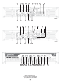 2
2
-
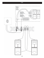 3
3
-
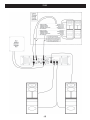 4
4
-
 5
5
-
 6
6
-
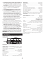 7
7
-
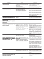 8
8
-
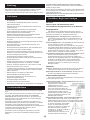 9
9
-
 10
10
-
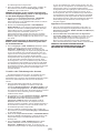 11
11
-
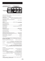 12
12
-
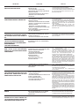 13
13
-
 14
14
-
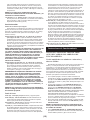 15
15
-
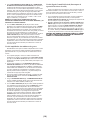 16
16
-
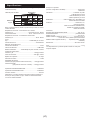 17
17
-
 18
18
-
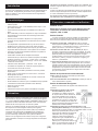 19
19
-
 20
20
-
 21
21
-
 22
22
-
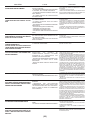 23
23
-
 24
24
-
 25
25
-
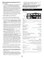 26
26
-
 27
27
-
 28
28


Gemini Stereo Amplifier XPM-3000 Manuale utente
- Categoria
- Amplificatori audio
- Tipo
- Manuale utente
- Questo manuale è adatto anche per