
D

The lightning flash with arrowhead symbol within an equilateral triangle is
intended to alert the user to the presence of uninsulated “dangerous” voltage
within the product's enclosure that may be of sufficient magnitude to constitute
a risk of electric shock to humans.
The exclamation point within an equilateral triangle is intended to alert the user
tothe presence of important operating and maintenance (servicing) instructions
in this manual.
The lightning flashes printed next to the output terminals of the amplifier are
intended to alert the user to the risk of hazardous energy. Output connectors
that could pose a risk are marked with the lightning flash. Do not touch output
terminals while amplifier power is on. Make all connections with amplifier
turned off.
CAUTION: TO REDUCE THE RISK OF ELECTRIC SHOCK, DO NOT REMOVE THE
COVER. NO USER-SERVICEABLE PARTS INSIDE. REFER SERVICING TO QUALI-
FIED PERSON NEL.
WARNING: To prevent fire or electric shock, do not expose this equipment to
rain or moisture.
This amplifier has a serial number located on the rear panel.
Please write this and the model number down and keep them for your records.
Keep your purchase receipt. It is your proof of purchase.
Serial Number:
Date of Purchase:
Purchased From:
Important Safety Precautions & Explanation of Symbols
1
The lightning flash with arrowhead symbol within an equilateral triangle is
intended to alert the user to the presence of uninsulated “dangerous” voltage
within the product's enclosure that may be of sufficient magnitude to constitute
a risk of electric shock to humans.
The exclamation point within an equilateral triangle is intended to alert the user
tothe presence of important operating and maintenance (servicing) instructions
in this manual.
The lightning flashes printed next to the output terminals of the amplifier are
intended to alert the user to the risk of hazardous energy. Output connectors
that could pose a risk are marked with the lightning flash. Do not touch output
terminals while amplifier power is on. Make all connections with amplifier
turned off.
CAUTION: TO REDUCE THE RISK OF ELECTRIC SHOCK, DO NOT REMOVE THE
COVER. NO USER-SERVICEABLE PARTS INSIDE. REFER SERVICING TO QUALI-
FIED PERSON NEL.
WARNING: To prevent fire or electric shock, do not expose this equipment to
rain or moisture.
Do not put any containers that hold water on the amplifier,
just in case the water would drip into the amplifier and cause electric shock.
This amplifier has a serial number located on the rear panel.
Please write this and the model number down and keep them for your records.
Keep your purchase receipt. It is your proof of purchase.
Serial Number:
Date of Purchase:
Purchased From:

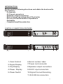
INTRODUCTION
CONTROLS, CONNECTORS & FEATURES
Please read the following directions and obtain the best results.
Key features:
- 4 channels
- XLR input connectors
- Speakon output connectors
- Each channel has independent Clip Limiter
ereo and - St Parallel modes of operations
- Reliability
- Complete amplifier protection
1 2 3 4 5 6 7 8 9 10
1 2 3 4 5 6 7 8 9 10 11
1- Gain Controll
2-Signal Display
3-Clip Display
4-Power Display
5-Power Switch
6-Serial number label
7-Power cord connector
8-Speakon output connectors
9-XLR-F input connectors
10-Signal Connect Selecting
11-XLR-M link connectors

12
3
Gnd
12
3
XLR INPUTS
1. Balanced input connections
XLR input connectors are electronically balanced;
XLR input connectors should be wired as follow:
Pin 1 Groud/ shield
Pin 2 positive (+)
Pin 3 negative (-)
2.Unbalanced input connections
To connect an input to an unbalanced source, it is possible to connect Pin1 and Pin3 in the XLR
plug at the amplifier end of the cable. However, a better method is to connect Pin3 to the shield at
the sourse end of the cable, as this usually results in better hum and noise rejection. Balanced input
connetions are recommended whenever possible.
SPEAKON OUPTPUTS
Each channel accepts a normal 2-wire cable. Stereo and parallel mode-
connect every speaker to the amplifier channel, and select stereo
or parallel mode as follow
Each channel is with a balanced XLR input connector. It's connected in a
standard way and can be changed quickly and easily. Balanced connect is
recommended so as to reduce the AC noise and interrupt, especially when
using long cable. Unbalanced connect should be used with short cable, and
the signal resistance should be no more than 600 ohms.
OUTPUT TERMINAL SAFETY WARNING!
Do not touch output terminals while amplifier power is on.
Turn off the amplifier before connecting, or else there will be risk
of hazardous energy!
Output Voltage Peak Limiter(VPL)
Voltage Peak Limiter (VPL) is a unique feature in D series amplifiers. It is used to select the maximum
power available on each output channel. The VPL allows you to set the correct output power for the
connected speakers to get to its best performance. The correct configuration is depended on the
system type and the load of connected channel.
If you choose a lower VPL setting, you only reduce the output voltage. At the same time, this allows
more current headroom for low-impedance loads. The amplifier thus runs at higher efficiency, with
a significantly reduced risk of going into thermal protection.
There's no bridge mode on this amplifier.
Do not support hot-plugging. Only plug in or out input signal when the power is off.
.
.
+
2 +
2 -
1 -
-1 +
SELECTING STEREO OR PARALLEL MODE
The amplifier can be set for normal Stereo operation or Parallel input Mode.
Stereo Mode - Each channel remains independent. The amplifier may be used
for two different signals.
Parallel Mode - This setting connects two input signal ( for 2-channel amplifier)
or four input signal ( for 4-channel amplifier)l together. One signal feeds both channels
(2-channel amplifier) or 4 channels(4-channel amplifier). Controlling by the input connector
and gain of channel A.
For 3 channel amplifier, it's without sucn function.
Do not connect different inputs to any side that opposites the channel
when operating in Parallel Mode.

GAIN CONTROLS
Turn the Gain controls clockwise to increase Gain and
counterclockwise to decrease Gain.
LED INDICATORS
Displays
The LED displays for each channel operate as follows:
Typical Power Up and Power Down Operation
When the amplifier is first turned on, the green POWER displays will light up , and there will
be a 2-second turn-on delay, during which all LEDs will be bright. The signal
LEDs are green.
CLIP LEDs not fully bright - maybe the output is overloaded or clip limiter is working
CLIP flashing and other LEDs are all on - the amplifier is reaching its full output, the clip circuit
is working to prevent overload output.
Overheat Situation:
When the ventilation is not good or the amplifier is overloaded under low impedance, it will
lead to the overheat protection.
The overheat protections is as follow:
25-50 : fans run in low speed ℃
50-60 : fans run from low speed to high ℃
75 : protection LEDs start to flash℃
85 : protection splash quickly and CLIP LED is illuminated, output is controlled at 15 dB℃
90 : overheat protection, the protection LEDs flash in high speed and the CLIP LED is fully ℃
bright, which shows the extreme low load, no ventilation or fans are broken.
POWER Green Main power supply active on this channel.
Clip LED on Shows activity of Limiting circuit,
which responds to both clipping and to thermal
overload.Protect Red Flashes as amplifier
approaches maximum temperature.
CLIP Yellow

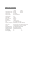
SPECIFICATIONS
D1000 D2004
8 Stereo Power 2X490W 4X400W ohms
4 Stereo Power 2X810W 4X640Wohms
Input connetor XLR female
Input impedance 20k ohms balanced
Input Sensitivity 0.77V
Input CMRR >80dB
Output connector Speakon
Hum&Noise >112dB
Damping Factor >1000 @ 8 ohms
THD <0.1% (20Hz-20kHz 1W)
Frequency Response 20HzЈ34KHz,(+0/-0.3dB, 1W/8ohms)
Level control front level meter, from negative infinity to 0dB
Cooling variable speed fans, front to rear airflow
Power Requirement AC voltage 180-240V 50-60Hz
A 88mmX488mmX438mplifier dimensions mm
acking dimensions 1 0mmX mm 5 0mmP 5 600 X 5
et weight(kg)N 5.7 6
ross weight(kg)G 6.6 6.9
-
 1
1
-
 2
2
-
 3
3
-
 4
4
-
 5
5
-
 6
6


FOS D2004 Manuale utente
- Tipo
- Manuale utente
- Questo manuale è adatto anche per
in altre lingue
- English: FOS D2004 User manual
Documenti correlati
Altri documenti
-
Yamaha T4n Manuale del proprietario
-
PROEL FLASH15P Manuale utente
-
-
Gemini Stereo Amplifier XPM-3000 Manuale utente
-
LD Systems XS700 PA Power Amplifier Manuale utente
-
Nexo R2 Manuale utente
-
-
PROEL HP-D 1500 Manuale utente
-