Mettler Toledo JagXtreme and Expressweigh Guida d'installazione
- Tipo
- Guida d'installazione

16396500A
12/01
In-Motion Weighing
Controllers
Installation Guide
and
®

Copyright 2001 Mettler-Toledo, Inc. This documentation contains proprietary information of Mettler-Toledo, Inc.
It may not be copied in whole or in part without the express written consent of Mettler-Toledo, Inc.
METTLER TOLEDO
®
reserves the right to make refinements or changes to the product or manual without notice.
U.S. Government Restricted Rights Legend: This software is furnished with Restricted Rights. Use, duplication, or
disclosure of the Software by the U.S. Government is subject to the restrictions as set forth in subparagraph (C)
(1) (ii) of the Rights in Technical Data and Computer Software clause at 40 C.F.R. Sec. 252.227-7013 or in
subparagraphs (c) (1) and (2) of the Commercial Computer Software-Restricted Rights clause at 40 C.F.R. Sec.
52-227-19, as applicable.

CUSTOMER FEEDBACK
Your feedback is important to us! If you have a problem with this product or its documentation, or a suggestion on how we can
serve you better, please fill out and send this form to us. Or, send your feedback via email to: quality_feedback.mtwt@mt.com
. If
you are in the United States, you can mail this postpaid form to the address on the reverse side or fax it to (614) 438-4355. If you
are outside the United States, please apply the appropriate amount of postage before mailing.
Your Name: Date:
Organization Name: METTLER TOLEDO Order Number
Address: Part / Product Name:
Part / Model Number:
Serial Number:
Phone Number: ( ) Fax Number: ( ) Company Name of Installation:
E-mail Address: Contact Name:
Phone Number:
How well did this product meet your
expectations in its intended use?
Comments:
Met and exceeded my needs
Met all needs
Met most needs
Met some needs
Did not meet my needs
PROBLEM:
UNACCEPTABLE DELIVERY: OUT OF BOX ERROR:
Shipped late Wrong item Wrong documentation
Shipped early Wrong part Missing documentation
Shipped to incorrect location Missing equipment Incorrectly calibrated
Other (Please Specify) Equipment failure Other (Please specify)
Comments:
DO NOT WRITE IN SPACE BELOW; FOR METTLER TOLEDO USE ONLY
Retail Light Industrial Heavy Industrial Systems
RESPONSE: Include Root Cause Analysis and Corrective Action Taken.

FOLD THIS FLAP FIRST
BUSINESS REPLY MAIL
FIRST CLASS PERMIT NO. 414 COLUMBUS, OH
POSTAGE WILL BE PAID BY ADDRESSE
E
Mettler-Toledo, Inc.
Quality Manager - MTWI
1150 Dearborn Drive
Worthington, OH 43085
USA
NO POSTAGE
NECESSARY IF
MAILED IN THE
UNITED STATES
Please seal with tape.

DECLARATION OF CONFORMITY
Konformitätserklärung
Déclaration de conformité
Declaración de Conformidad
Conformiteitsverklaring
Dichiarazione di conformità
We/Wir/Nous/Wij/Noi: Mettler-Toledo, Inc.
1150 Dearborn Drive
Worthington, Ohio 43085
USA
declare under our sole responsibility that the product,
erklären, in alleiniger Verantwortung, daß dieses Produkt,
déclarons sous notre seule responsabilité que le produit,
declaramos, bajo nuestra sola responsabilidad, que el producto,
verklaren onder onze verantwoordelijkheid, dat het product,
dichiariamo sotto nostra unica responsabilitá, che il prodotto,
Model/Type: 9482
to which this declaration relates is in conformity with the following standard(s) or other normative document(s).
auf das sich diese Erklärung bezieht, mitder/den folgenden Norm(en) oder Richtlinie(n) übereinstimmt.
Auquel se réfère cette déclaration est conforme à la (aux) norme(s) ou au(x) document(s) normatif(s).
Al que se refiere esta declaración es conforme a la(s) norma(s) u otro(s) documento(s) normativo(s).
Waarnaar deze verklaring verwijst, aan de volende norm(en) of richtlijn(en) beantwoordt.
A cui si riferisce questa dichiarazione è conforme alla/e sequente/i norma/e o documento/i normativo/i.
in combination with a weighing platform produced by Mettler-Toledo is in conformity with the following directives and standards.
Council directive on the harmonization of the laws of the Member states: standards:
relating to electromagnetic compatibility (89/336/EEC) amended by directive (93/68/EEC;
92/31/EEC)
EN 55022 B
EN 61000-3-2
EN 61000-3-3
EN 61000-4-2
EN 61000-4-3 (3 V/m)
EN 61000-4-4
EN 61000-4-5
relating to electrical equipment designed for use within certain voltage limits (73/23/EEC
amended by directive (93/68/EEC)
EN 60950
Worthington, Ohio USA, November, 2001 Mettler-Toledo, Inc.
Darrell Flocken, Manager - Weights & Measures
Office of Weights and Measures
Original issue: November, 2001
According to EN 45014

We/Wir/Nous/Wij/Noi: Mettler-Toledo, Inc.
1150 Dearborn Drive
Worthington, Ohio 43085
USA
declare under our sole responsibility that the product,
erklären, in alleiniger Verantwortung, daß dieses Produkt,
déclarons sous notre seule responsabilité que le produit,
declaramos, bajo nuestra sola responsabilidad, que el producto,
verklaren onder onze verantwoordelijkheid, dat het product,
dichiariamo sotto nostra unica responsabilitá, che il prodotto,
Model/Type: JAGXTREME - Factory Number JXGAD003000
to which this declaration relates is in conformity with the following standard(s) or other normative document(s).
auf das sich diese Erklärung bezieht, mitder/den folgenden Norm(en) oder Richtlinie(n) übereinstimmt.
Auquel se réfère cette déclaration est conforme à la (aux) norme(s) ou au(x) document(s) normatif(s).
Al que se refiere esta declaración es conforme a la(s) norma(s) u otro(s) documento(s) normativo(s).
Waarnaar deze verklaring verwijst, aan de volende norm(en) of richtlijn(en) beantwoordt.
A cui si riferisce questa dichiarazione è conforme alla/e sequente/i norma/e o documento/i normativo/i.
in combination with a weighing platform produced by Mettler-Toledo is in conformity with the following directives and standards.
Council directive on the harmonization of the laws of the Member states: standards:
relating to electromagnetic compatibility (89/336/EEC) amended by directive (93/68/EEC;
92/31/EEC)
EN 55022 B
EN 61000-3-2
EN 61000-3-3
EN 61000-4-2
EN 61000-4-3 (3 V/m)
EN 61000-4-4
EN 61000-4-5
relating to electrical equipment designed for use within certain voltage limits (73/23/EEC
amended by directive (93/68/EEC)
EN 60950
Worthington, Ohio USA, November, 2001 Mettler-Toledo, Inc.
Darrell Flocken, Manager - Weights & Measures
Office of Weights and Measures
Original issue: November, 2001
DECLARATION OF CONFORMITY
Konformitätserklärung
Déclaration de conformité
Declaración de Conformidad
Conformiteitsverklaring
Dichiarazione di conformità
According to EN 45014

FCC Notice
This device complies with Part 15 of the FCC Rules and the Radio Interference Requirements of the
Canadian Department of Communications. Operation is subject to the following conditions: (1) this device
may not cause harmful interference, and (2) this device must accept any interference received, including
interference that may cause undesired operation.
This equipment has been tested and found to comply with the limits for a Class A digital device, pursuant
to Part 15 of FCC Rules. These limits are designed to provide reasonable protection against harmful
interference when the equipment is operated in a commercial environment. This equipment generates,
uses, and can radiate radio frequency energy and, if not installed and used in accordance with the
instruction manual, may cause harmful interference to radio communications. Operation of this equipment
in a residential area is likely to cause harmful interference in which case the user will be required to correct
the interference at his or her own expense.
ORDERING INFORMATION
It is most important that the correct part number is used when ordering parts. Parts orders are machine
processed, using only the part number and quantity as shown on the order. Orders are not edited to determine
if the part number and description agree.
COPYRIGHT
METTLER TOLEDO
®
, JAGXTREME
®
, and EXPRESSWEIGH
®
are registered trademarks of Mettler-Toledo, Inc.
All other brand or product names are trademarks or registered trademarks of their respective companies.

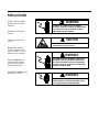
PRECAUTIONS
WARNING
DISCONNECT ALL POWER TO THIS UNIT BEFORE
INSTALLING, SERVICING, CLEANING, OR REMOVING THE
FUSE. FAILURE TO DO SO COULD RESULT IN BODILY
HARM AND/OR PROPERTY DAMAGE.
CAUTION
OBSERVE PRECAUTIONS FOR HANDLING
ELECTROSTATIC SENSITIVE DEVICES.
WARNING
ONLY PERMIT QUALIFIED PERSONNEL TO SERVICE THIS
EQUIPMENT. EXERCISE CARE WHEN MAKING CHECKS,
TESTS AND ADJUSTMENTS THAT MUST BE MADE WITH
POWER ON. FAILING TO OBSERVE THESE PRECAUTIONS
CAN RESULT IN BODILY HARM.
WARNING
FOR CONTINUED PROTECTION AGAINST SHOCK
HAZARD, CONNECT TO PROPERLY GROUNDED OUTLET
ONLY. DO NOT REMOVE THE GROUND PRONG.
READ this manual BEFORE
operating or servicing this
equipment.
FOLLOW these instructions
carefully.
SAVE this manual for future
reference.
DO NOT allow untrained
personnel to operate, clean,
inspect, maintain, service, or
tamper with this equipment.
ALWAYS DISCONNECT this
equipment from the power
source before cleaning or
performing maintenance.
CALL METTLER TOLEDO for parts,
information, and service.

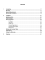
CONTENTS
1 Introduction...................................................................................................1-1
Mounting.......................................................................................................1-1
Electrical Requirements ..................................................................................1-2
Options and Accessories.................................................................................1-3
2 Installation ....................................................................................................2-1
Suitable Location............................................................................................2-1
Cable Entrances.............................................................................................2-1
Wire Terminations ..........................................................................................2-2
AC Power .............................................................................................2-2
Load Cell..............................................................................................2-3
Photo Eyes ...........................................................................................2-3
Discrete Signal Inputs.............................................................................2-5
Discrete Signal Outputs...........................................................................2-6
Serial Ports ...........................................................................................2-7
Routing and Securing Cables...........................................................................2-7
Programming.................................................................................................2-8
Closing the Enclosures ...................................................................................2-8
3 Drawings.......................................................................................................3-1


Chapter 1: Introduction
Mounting
(12-01) 1-1
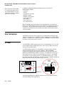
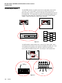
1 Introduction
The JAGXTREME in-motion controller and the 9482 EXPRESSWEIGH controller are
designed to provide high speed processing of in-motion weights from boxes or other
products as they pass over an analog load cell scale conveyor. The resultant weight is
displayed and may also be transmitted to a peripheral such as a printer or computer.
The JAGXTREME in-motion controller consists of a general purpose JAGXTREME terminal
with a single analog scale interface and custom hardware and software designed for
high speed weight processing. This version requires ASCII commands to begin and end
the weight processing.
The EXPRESSWEIGH controller consists of a METTLER TOLEDO panel mount
JAGXTREME terminal installed in a stainless steel certified TYPE 4 and TYPE 12
enclosure. An analog load cell interface is provided for one scale only. Custom
hardware and software designed for high speed weight processing have been added to
provide a complete solution for in-motion weighing. This version is designed to connect
to DC photo eyes or switches to begin and end the weight processing cycle.
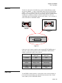
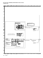
Mounting
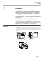
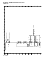
The JAGXTREME in-motion controller is designed to sit on a desk or other flat surface.
An optional bracket is available to mount this unit to a wall or column. The JAGXTREME
controller's overall dimensions and mounting dimensions with the optional bracket are
shown in Figure 1-1.
12.45"
(31.6 cm)
10.06"
(25.6 cm)
12.31"
(31.3 cm)
7.86"
(20 cm)
10.59"
(26.9 cm)
115°
25°
Figure 1-1

METTLER TOLEDO JAGXTREME and EXPRESSWEIGH In-Motion Controllers
Installation Guide
(12-01) 1-2
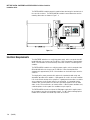
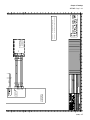
The EXPRESSWEIGH controller mounts to a wall or floor stand using the four brackets at
the rear of the enclosure. The EXPRESSWEIGH controller's overall dimensions and the
mounting dimensions are shown in Figure 1-2.
Electrical Requirements
The JAGXTREME controller uses a switching power supply, which can operate from 85
to 264 VAC with a line frequency of 47 to 63 Hz. Power consumption is approximately
20 VA. All terminations are via terminal strip connectors inside the rear housing of the
controller.
The EXPRESSWEIGH controller uses switching power supplies, which can operate from
85 to 264 VAC with a line frequency of 47 to 63 Hz. Power consumption of the
standard unit is approximately 25 VA. All terminations are via terminal strips inside the
enclosure.
The integrity of the power ground for this equipment is important for both safety and
dependable operation of the controller. A poor ground can result in an unsafe condition
if an electrical short develops in the equipment. A good ground connection is needed to
assure extraneous electrical noise influences are minimized. It is important that the
controller does not share power lines with noise generating equipment such as motor
starter circuits, RF thermal heaters, or inductive loads. If adverse power conditions exist,
a dedicated power circuit or power line conditioner may be required.
The EXPRESSWEIGH includes an internal 24 VDC power supply which supplies power
for the photoeyes and discrete input/output signals. The I/O is buffered through optical
isolators and is available on terminal strips inside the enclosure.
Figure 1-2
WEIGHEXPRESS

Chapter 1: Introduction
Options and Accessories
(12-01) 1-3
Options and Accessories
The following optional PCBs are compatible with both the JAGXTREME and
EXPRESSWEIGH controllers:
• 0917-0223 - Multifunction PCB - Adds two additional serial ports.
• 0917-0213 - Allen-Bradley RIO I/F - Provides connectivity to Allen Bradley PLCs.
• 0917-0243 - PROFIBUS I/F - Provides connectivity to PROFIBUS-compatible PLC
signals.
• 0900-0311 - PROFIBUS pigtail cable - Extends PROFIBUS connection to outside the
general purpose JAGXTREME enclosure.
• 0917-0250 - PROFIBUS DP type files - Description of communication parameters for
PROFIBUS system.
• 0917-0254 - Modbus Plus I/F - Provides connectivity to PLCs using Modbus Plus
• 0900-0320 - Modbus Plus pigtail cable - Extends Modbus Plus connection to
outside the general purpose JAGXTREME enclosure.
In addition, the following accessories are available:
• 0917-0209 - JAGXTREME controller wall/column mount kit - Bracket that mounts the
general purpose JAGXTREME enclosure to a wall or column.
• 0917-0338 - EXPRESSWEIGH controller spare parts kit - Kit that includes spare
parts, which might be needed for service of the EXPRESSWEIGH controller.

METTLER TOLEDO JAGXTREME and EXPRESSWEIGH In-Motion Controllers
Installation Guide
(12-01) 1-4
NOTES

Chapter 2: Installation
Suitable Location
(12-01)
2-1
2 Installation
Suitable Location
Before installing the JAGXTREME in-motion controller or the EXPRESSWEIGH controller,
select an appropriate location for the controller in an area where exposure to severe
environmental conditions such as dust, dirt, moisture, vibration, etc. is minimized. Care
should be taken to ensure sufficient space is provided around the enclosure to allow for
adequate ventilation and easy access through the rear panel of the JAGXTREME
controller or the front door of the EXPRESSWEIGH controller. In addition, make sure
enough space is also provided at the bottom of the EXPRESSWEIGH controller's
enclosure for all cable entrances.
The JAGXTREME controller has been designed to meet TYPE 4 standards, and the
EXPRESSWEIGH controller has been tested and certified to TYPE 4 and TYPE 12
enclosure ratings.
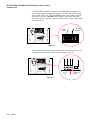
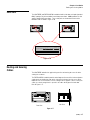
Cable Entrances
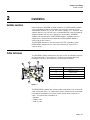
The JAGXTREME in-motion controller does not require special considerations for routing
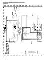
input and output cables. Refer to Figure 2-1 below for a description of which grip
bushing to use for which connection on the rear housing of the controller.
Reference Letter Suggested Cable
A QWERTY Keyboard
B Ethernet Cable
C Serial I/O Cables, PLC I/F Cabling
D Analog Load Cell Cabling
The EXPRESSWEIGH controller does not have factory-installed holes in the enclosure for
cables entering and exiting. The required holes must be made at the time of installation
based upon the orientation of the enclosure and the desired entrance points for the
cables. The required inputs and outputs are:
• AC power
• Photoeye cable
• Load cell cable
Figure 2-1
C
B
A
D

METTLER TOLEDO JAGXTREME and EXPRESSWEIGH In-Motion Controllers
Installation Guide
(12-01) 2-2
In addition, the following optional inputs/outputs may be required for the
EXPRESSWEIGH controller:
• Serial ports
• Ethernet
• PLC interface connections
• QWERTY keyboard
• Controller running output
• Scale empty output
• Alarm output
• Silence alarm input
• Run Permissive input
METTLER TOLEDO recommends that these input and output holes be located on the
bottom of the EXPRESSWEIGH enclosure to best maintain the environmental integrity of
the enclosure. All connections to the enclosure must be sealed appropriately for the
environment and installed correctly according to all national, local and other relevant
electrical standards.
Wire Terminations
The following sections describe the requirements for routing and terminating the input
and output connections to the JAGXTREME in-motion controller and the EXPRESSWEIGH
controller. In addition, there is a wiring schematic (p/n 907505R) in the last section of
this manual, which may be used as a reference.
AC Power
The JAGXTREME in-motion controller comes with a standard AC power cord. This cord
may be plugged into any suitable power source, which meets the power requirements
described in the previous chapter.
The EXPRESSWEIGH controller must have AC power run to the enclosure (typically
through conduit depending upon electrical regulations). METTLER TOLEDO
recommends the AC power input should be brought in at the back right corner of the
bottom of the EXPRESSWEIGH controller's enclosure. This provides the easiest access
to the terminals and fuse module for the high voltage lines marked X1, X2 and GND.
Refer to Figure 2-2 for the location of the X1, X2 and GND terminals on TB1. Power
lines running more than one foot (0.3m) internal to the enclosure should be twisted and
routed as far away from other low voltage wiring as practical.
Any external high voltage lines (40 volts and higher) must be run separate from any
external low voltage control signal wiring.
Figure 2-2
Hot
(black)
Ground
(green)
Neutral
(white)
TB
1
Note: To maintain TYPE 4 and/or
12 environmental rating, wiring is
to be provided through UL Listed
conduit hubs, fittings or equivalent
of the same TYPE rating.

Chapter 2: Installation
Wire Terminations
(12-01)
2-3
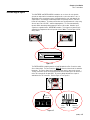
Load Cell
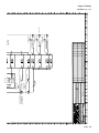
The load cell cable must be terminated on the rear of the Analog PCB to the terminal
strip labeled “CHANNEL 1” in both the JAGXTREME controller and the EXPRESSWEIGH
controller. Figure 2-3 below shows the load cell connector on the rear of the Analog
PCB where the incoming load cell cable is to be terminated. METTLER TOLEDO includes
a 25-foot (8 m) length of six conductor, shielded 24-gauge load cell cable (p/n
14264100A) with the EXPRESSWEIGH controller for this purpose. There is no load cell
cable included with the JAGXTREME controller.
A color code chart is shown next with the most common METTLER TOLEDO load cell
color codes. Before connecting load cells to the JAGXTREME or EXPRESSWEIGH
controller, confirm which signal is which color wire.
Signal Name 6-Wire Load Cell
Color Code
4-Wire Load Cell
Color Code
+ Excitation White Green
+ Sense Yellow (jumper to + Ex.)
+Signal Green White
Ground Orange (shield) Yellow (orange)
- Signal Black Red
-Sense Red (jumper to - Ex.)
- Excitation Blue Black
Photo Eyes
The JAGXTREME in-motion controller is not designed to connect directly to photo eyes
but is meant to be operated with serial commands from a host device only. Do not
connect photo eyes to the JAGXTREME controller.
Figure 2-3
JAGXTREME
controller
EXPRESSWEIGH
controller
+EXC
+SEN
+SIG
SHLD
-SIG
-SEN
-EXC
15VDC ANALOG
A/D
A -STATUS - B
CHANNEL 1

METTLER TOLEDO JAGXTREME and EXPRESSWEIGH In-Motion Controllers
Installation Guide
(12-01) 2-4
The EXPRESSWEIGH controller is compatible with 24 VDC photo eyes or arrays. The
24-volt supply and ground to power the photo eyes is available from the TB1 terminal
strip as shown in Figure 2-4. METTLER TOLEDO includes a four-conductor, 16-gauge,
25-foot (8 m) cable (p/n 15099800A) for this purpose. Other cables with similar
specifications may be substituted if required. If another cable is used, the colors shown
next may be different.
This four-conductor cable is also used to route the input signals from the entrance and
exit photoeyes back to terminals 1 and 3 on TB2 as shown in Figure 2-5.
Figure 2-4
0 Volts
(Green)
Figure 2-5
Entrance PE
(white)
Exit PE
(red)
0 Volts
(Green)
24 Volts
DC
(
Black
)

Chapter 2: Installation
Wire Terminations
(12-01)
2-5
Discrete Signal Inputs
The JAGXTREME and EXPRESSWEIGH controllers can receive a discrete signal to
generate an output of the instantaneous weight on the scale or to zero the scale. In
applications where a package or parcel is brought onto the scale and stopped, this
signal may be used to trigger a data output before the package exits the scale and
breaks the exit photoeye. A custom print function must be programmed in setup using
discrete input 3 or 4 on PAR 1 and wired appropriately. The zero command only
operates within normal operating parameters of the zero function. No other input
signals are supported on the JAGXTREME controller. This trigger must connect logic
ground to the programmed discrete input for at least 100ms. Refer to Figure 2-6 for
wiring details.
The EXPRESSWEIGH controller provides 24-volt DC optos for a Run Permissive and a
Silence Alarm input. The Run Permissive MUST BE
connected in order for the controller
to operate. The Silence Alarm input is not required but may be connected if desired.
The Run Permissive input is on terminal 5 and the Silence Alarm input is on terminal 7
of the TB2 connector on the opto PCB. The source voltage for both these inputs is
available on the TB1 connector. Refer to Figure 2-7 for specifics.
Figure 2-7
Figure 2-6
+5v
OUT1
OUT2
OUT3
OUT4
IN1
IN2
IN3
IN4
GND
PAR 2 PAR 1 KEYBOARD
Source - 24
Volts DC
Silence
Alarm
(optional)
Run
Permissive
(required)

METTLER TOLEDO JAGXTREME and EXPRESSWEIGH In-Motion Controllers
Installation Guide
(12-01) 2-6
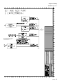
Discrete Signal Outputs
The JAGXTREME controller can provide simple discrete signal outputs, which indicate
scale status. These include motion, center of zero, over capacity and under zero.
Connection for these outputs are made on the PAR2 output terminal block on the back of
the Controller PCB. These output signals are typically routed through an Opto 22 device
to convert to a higher voltage level. Only OUT4 can be used in the EXPRESSWEIGH
controller. Typical connections are shown in Figure 2-8 below.
The EXPRESSWEIGH controller provides three custom discrete output signals - Alarm,
Scale Empty and Scale Running. These signals are available on terminals 10, 12 and
14 respectively on terminal block TB2. All of these signals are designed to be
referenced to the 0 volt DC terminal on TB1. Refer to Figure 2-9 for a pictorial view.
Figure 2-9
Figure 2-8
+5V
OUT1
OUT2
OUT3
OUT4
OPTO
OPTO
OPTO
OPTO
+5v
OUT1
OUT2
OUT3
OUT4
IN1
IN2
IN3
IN4
GND
PAR 2 PAR 1 KEYBOARD
Return -
0 Volts DC
Running
Scale Empty
Alarm
La pagina sta caricando ...
La pagina sta caricando ...
La pagina sta caricando ...
La pagina sta caricando ...
La pagina sta caricando ...
La pagina sta caricando ...
La pagina sta caricando ...
La pagina sta caricando ...
La pagina sta caricando ...
La pagina sta caricando ...
La pagina sta caricando ...
La pagina sta caricando ...
La pagina sta caricando ...
La pagina sta caricando ...
-
 1
1
-
 2
2
-
 3
3
-
 4
4
-
 5
5
-
 6
6
-
 7
7
-
 8
8
-
 9
9
-
 10
10
-
 11
11
-
 12
12
-
 13
13
-
 14
14
-
 15
15
-
 16
16
-
 17
17
-
 18
18
-
 19
19
-
 20
20
-
 21
21
-
 22
22
-
 23
23
-
 24
24
-
 25
25
-
 26
26
-
 27
27
-
 28
28
-
 29
29
-
 30
30
-
 31
31
-
 32
32
-
 33
33
-
 34
34


Mettler Toledo JagXtreme and Expressweigh Guida d'installazione
- Tipo
- Guida d'installazione
in altre lingue
Documenti correlati
-
Mettler Toledo JagXtreme (Division 2 and Zone 2/22) Guida d'installazione
-
-
-
-
-
-
-
-
-
Altri documenti
-
Omega DP500 Series Manuale del proprietario
-
CARLO GAVAZZI G34409943824 Guida d'installazione
-
 Brooks 0251 / 0254 Istruzioni per l'uso
-
Mitsubishi α Series Manuale del proprietario
-
Seneca R-SG3 Guida d'installazione
-
ETC Unison Paradigm P-TS7 Guida d'installazione
-
AMG AMG2744-DR Instruction Sheet
-
 Rockwell Automation Bulletin 855BS LED Manuale utente

